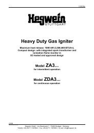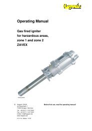
Operating and mounting manual Safety shut off valve gas ...
Operating and mounting manual Safety shut off valve gas ...
Operating and mounting manual Safety shut off valve gas ...
- No tags were found...

You also want an ePaper? Increase the reach of your titles
YUMPU automatically turns print PDFs into web optimized ePapers that Google loves.
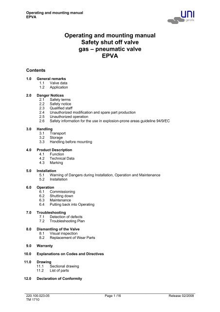
<strong>Operating</strong> <strong>and</strong> <strong>mounting</strong> <strong>manual</strong>EPVA<strong>Operating</strong> <strong>and</strong> <strong>mounting</strong> <strong>manual</strong><strong>Safety</strong> <strong>shut</strong> <strong>off</strong> <strong>valve</strong><strong>gas</strong> – pneumatic <strong>valve</strong>EPVAContents1.0 General remarks1.1 Valve data1.2 Application2.0 Danger Notices2.1 <strong>Safety</strong> terms2.2 <strong>Safety</strong> notice2.3 Qualified staff2.4 Unauthorized modification <strong>and</strong> spare part production2.5 Unauthorized operation2.6 <strong>Safety</strong> information for the use in explosion-prone areas guideline 94/9/EC3.0 H<strong>and</strong>ling3.1 Transport3.2 Storage3.3 H<strong>and</strong>ling before <strong>mounting</strong>4.0 Product Description4.1 Function4.2 Technical Data4.3 Marking5.0 Installation5.1 Warning of Dangers during Installation, Operation <strong>and</strong> Maintenance5.2 Installation6.0 Operation6.1 Commissioning6.2 Shutting down6.3 Maintenance6.4 Putting back into <strong>Operating</strong>7.0 Troubleshooting7.1 Detection of defects7.2 Troubleshooting Plan8.0 Dismantling of the Valve8.1 Visual inspection8.2 Replacement of Wear Parts9.0 Warranty10.0 Explanations on Codes <strong>and</strong> Directives11.0 Drawing11.1 Sectional drawing11.2 List of parts12.0 Declaration of Conformity________________________________________________________________________________________________________220.100.023-05 Page 1 /16 Release 02/2008TM 1710
<strong>Operating</strong> <strong>and</strong> <strong>mounting</strong> <strong>manual</strong>EPVA1.0 General remarksThis operating <strong>manual</strong> includes instructions to assemble <strong>and</strong> operate the <strong>valve</strong> in the prescribed <strong>and</strong>safe way. Additionally <strong>and</strong> in accordance with the solenoid drive of the control <strong>valve</strong> (805), therelavant manufacturer’s operating instructions (BTA) must be taken into consideration.If any difficulties appear that can not be solved by means of the operating <strong>manual</strong>, further informationmay be dem<strong>and</strong>ed from the manufacturer.This operating <strong>manual</strong> is in accordance with the relevant valid EN safety st<strong>and</strong>ards <strong>and</strong> the validprescriptions <strong>and</strong> rules of the Federal Republic of Germany.If the solenoids are used abroad of the FRG, the operator <strong>and</strong>/or the person who is responsible for theplant concept must take care that the valid national rules are met.The manufacturer reserves the right of any technical change <strong>and</strong> improvement.The use of these operation instructions suppose the qualification of the user according to paragraph2.3 “qualified staff”.The operating staff must be trained in accordance with the operating instructions. The operation<strong>manual</strong> must always be available at the location where used.1.1 Valve dataManufacturer:UNI Geräte E. MangelmannElektrotechnische Fabrik GmbHHoltumsweg 13D-47652 WeezeTelefon: +49 (0) 2837/9134-0Fax: +49 (0) 2837/1444E-Mail: info@uni-geraete.deHomepage: www.uni-geraete.deDesignationDirectly functioning, currentless closed, spring safety <strong>shut</strong> <strong>off</strong> <strong>valve</strong> with pneumatic drive.Type test acc. to 90/396/EEC Prod. Id. Nr. CE-0085AQ0211DIN EN 161 Kl. A, Gr. 2DIN 3394-1Gr. AWorking pressure: 1-4(5)-EPVA 0 - 1 bar2-4(7)-EPVA 0 - 2 bar2,5-6-EPVA 0 - 2,5bar3-4-EPVA 0 - 3 bar4-4-EPVA 0 - 4 bar6-4-EPVA 0 - 6 barAmbient temperature: -20°C bis + 60°CMedium temperature: -20°C bis + 60°CFitting position:vertical or horizontal drive.Switching cycles:1000 cycles/hFlange connection measures acc. to DIN EN 1092-2 / ANSIFlange DNFlange ANSIPN 151/2"203/4"251”4011/2”502”6521/2”803”1004”Design pressurePS = PN1-4-EPVA…. 16 - - - - - - X - PN 62-4-EPVA.... 16 - - - - X X - - PN 63-4-EPVA.... 16 - - - X - - - X PN 66-4-EPVA.... 16 X X X X X X X X PN 16Flange DNFlange ANSIPN 125-1506”2008”25010”300-350-400-Design pressurePS = PN1-4-EPVA.... 16 - X X X X - X PN 61-5-EPVA…. 16 - - - - - X - PN 62-4-EPVA.... 16 X - X - - - - PN 62-7-EPVA.... 16 - - - - - X PN 62,5-6-EPVA… 16 - X - - - - - PN 6________________________________________________________________________________________________________220.100.023-05 Page 2 /16 Release 02/2008TM 1710
<strong>Operating</strong> <strong>and</strong> <strong>mounting</strong> <strong>manual</strong>EPVAFlange DNFlange ANSIPN 125-1506”2008”25010”300-350-400-Design pressurePS = PN4-4-EPVA.... 16 - X - - - - - PN 66-4-EPVA.... 16 X - - - - - - PN 16X Type test acc. to 90/396/EEC, O Acceptance test certificate 3.2 possible, - not available,Control medium:Control pressure:Electric connection control <strong>valve</strong>:Air, nitrogen –20°C up to +60°CMin. control pressure, second number on type plateMax. control pressure 10bar, e.g. 4-10 barNotice instructions on type plate of control <strong>valve</strong>.1.2 ApplicationThe UNI Geräte <strong>gas</strong>- pneumatic <strong>valve</strong>s EPVA <strong>and</strong> are used as automatic safety <strong>shut</strong> <strong>off</strong> <strong>valve</strong>s tosecure, to limit, <strong>shut</strong>-<strong>off</strong> <strong>and</strong> release <strong>gas</strong> <strong>and</strong> air supply at main <strong>shut</strong>-<strong>off</strong> devices or in front of <strong>gas</strong>burners e.g. acc. to DIN EN 746-2.The <strong>valve</strong>s are suitable for <strong>gas</strong>es of the 1 st , 2 nd <strong>and</strong> 3 rd <strong>gas</strong> families to G260 <strong>and</strong> for neutral <strong>gas</strong>es <strong>and</strong>as a variant with material design for aggressive <strong>gas</strong>es such as e.g. bio<strong>gas</strong>, sewage plant <strong>gas</strong> or dump<strong>gas</strong> to G262.If used in other cases, the operator must carefully check if construction/design of <strong>valve</strong>, accessories<strong>and</strong> materials are suitable for the new application. The range of application is subject to theresponsibilty of the plant planner. The service life of the <strong>valve</strong> is 20 years.2.0 Danger Notices2.1 <strong>Safety</strong> termsThe signal terms DANGER, CAUTION und NOTICE are used in this operating <strong>manual</strong> in case ofnotices concerning special dangers, or for unusal information requiring a special marking.DANGER! means that in case of non-observance there is danger to life <strong>and</strong>/orconsiderable damage.CAUTION! means that in case of non-observance there is danger of injury <strong>and</strong>/ordamage.NOTICE! means that attention is drawn to technical correlations/connections.Observance of other, not especially marked notices concerning transport, assembly, operation <strong>and</strong>maintenance <strong>and</strong> other data (in the operating <strong>manual</strong>, product documentation <strong>and</strong> at the unit itself) isalso essential, in order to avoid disturbances that might affect direct or indirect damage to property orinjury to persons.2.2 <strong>Safety</strong> noticeNon observance of safety instructions can lead to loss of any claim for damages.Non observance can lead to the following mentioned dangers:• Failure of important functions of the <strong>valve</strong>/plant• Endangering of persons by electrical or mechanical influences.• Protection against accidental contact for moving parts may not be removed as long as the<strong>valve</strong> is in operation.• Leakage of dangerous media (e.g. explosive, toxic, hot) must be removed in the way thatthere is no danger for persons or environment. Laws <strong>and</strong> regulations must be observed.________________________________________________________________________________________________________220.100.023-05 Page 3 /16 Release 02/2008TM 1710
<strong>Operating</strong> <strong>and</strong> <strong>mounting</strong> <strong>manual</strong>EPVA2.3 Qualified staffThese are persons who are familiar with erection, assembly, starting, operation <strong>and</strong> maintenance ofthe product <strong>and</strong> who have special qualifications acc. to their activities <strong>and</strong> functions, e.g.:• Instruction <strong>and</strong> obligation to carry out <strong>and</strong> meet all regional <strong>and</strong> in-house orders <strong>and</strong>requirements.• Education or instruction according to the safety engineering st<strong>and</strong>ards in use <strong>and</strong>maintenance of adequate safety <strong>and</strong> working protection equipment.• Training in first aid.2.4 Unauthorized Modification <strong>and</strong> Spare Part ProductionModification or changes of the <strong>valve</strong> are only allowed after agreement of the manufacturer. Originaldrawings <strong>and</strong> accessories authorized by the manufacturer are for safety purposes. The use of otherparts or unauthorized constructive changes at the <strong>valve</strong> by third persons may cancel <strong>and</strong> abolish themanufacturere’s liability for resulting consequences.2.5 Unauthorized OperationOperational reliability of the delivered <strong>valve</strong> is only guaranteed in case of determined use inaccordance to paragraph 1 of the operating <strong>manual</strong>. The application limits mentioned on the typesign may on no account be exceeded.2.6 <strong>Safety</strong> information for the use in explosion-prone areas guideline 94/9/EC• The temperature of the medium must not exceed the respective temperature class, <strong>and</strong>respectively, the respective maximum permitted medium temperature as per operationguideline.• If the <strong>valve</strong> is heated (e.g. heating jacket), care must be taken, that the specified temperatureclass is kept in the time.• The <strong>valve</strong> must be connected to the ground.In the case most simple this can be realized via pipe screws by means of tooth disc.Otherwise the connection to the ground must be implemented by other measures e.g. cablelinks.• Control <strong>valve</strong>s, electrical <strong>and</strong> electrical/mechanical drives as well as sensors must undergo aseparate conformity check as per ATEX. In doing so the respective safety <strong>and</strong> explosionprotection information in the operation instructions are to taken into special consideration.Furthermore we point out the guideline 95/C332/06(ATEX 118a), which include the minimumregulations for the improvement of the health-related situation <strong>and</strong> the safety of the employees, whomight be jeopardized by an explosive atmosphere.3.0 H<strong>and</strong>ling3.1 TransportFor any transport works, the generally recognised technical rules <strong>and</strong> st<strong>and</strong>ards as well as rules forprevention of accidents must be observed.In case of transport, storage <strong>and</strong> stopping, the flange protection caps must be mounted at both <strong>valve</strong>flanges.The goods to be transported must be carefully treated. During transport, the <strong>valve</strong> must be protectedagainst strokes, impacts or vibration. The coat of lacquer may not be damaged. Transport temperatureis –20°C up to +60°C.Never transport the <strong>valve</strong> at pneumatic drive pipings/tubings or components. Transport the<strong>valve</strong> at provided transport angles (256) from KA120 or ring nut (926) from KA160.Transport the <strong>valve</strong> in a box or on a pallet with soft base <strong>and</strong> put it smoothly on even floor. Never put<strong>valve</strong> on the piping/tubing or its components.The goods must be checked on completeness <strong>and</strong> transport damage. See also section 9.0________________________________________________________________________________________________________220.100.023-05 Page 4 /16 Release 02/2008TM 1710
<strong>Operating</strong> <strong>and</strong> <strong>mounting</strong> <strong>manual</strong>EPVA3.2 StorageIf the <strong>valve</strong> is not installed immediately after delivery, it must be stored properly.• Storage temperature -20°C up to +60°C, dry <strong>and</strong> clean.• The lacquering protects against corrosion in neutral dry atmosphere. Do not damage colour.• In humid rooms, a drying agent or a heating resp. is necessary because of condesation ofwater.Requirements according to DIN 7716 (products made of caoutchouc <strong>and</strong> rubber) must be met.3.3 H<strong>and</strong>ling before Mounting• In case of <strong>valve</strong> with protection caps, they must be removed before being mounted!• Protect against atmospheric influences such as humidity (otherwise use drying agent).• Appropriate treatment protects against damage.4.0 Product DescriptionThe UNI-Geräte <strong>gas</strong>-pneumatic <strong>valve</strong> EPVA is a directly controlled, currently-closed, quickly closingsafety <strong>shut</strong>-<strong>off</strong> <strong>valve</strong> acc. To DIN EN 13611, DIN 3394-1 <strong>and</strong> DIN EN 161 with pneumtaic drive.The drive is actuated by a 3/2 way control <strong>valve</strong> with solenoid drive, type 10-EVD 2 or 10-EVD 2/2401resp.The sectional drawing part 11.1 in Fig. 1 <strong>and</strong> 2 shows the <strong>valve</strong> construction.4.1 FunctionWhen opening the 3/2 way control <strong>valve</strong> (805) the control medium flows via the connection 3 → 2under the drive piston (217). The control medium pushes the drive piston (217) against the pressuresprings (503) <strong>and</strong> opens - via the <strong>valve</strong> spindle (205) – the <strong>valve</strong> disk that is pressure impinged (200).The <strong>valve</strong> is open.The <strong>valve</strong> closes in case of <strong>shut</strong>-<strong>off</strong>, failure or interruption of power energy to control <strong>valve</strong> (805). Thecompressed control medium in the pneumatic drive is blown-<strong>off</strong> via the quick-venting mechanism(601) with sound absorber (600) <strong>and</strong> the control <strong>valve</strong> (805). Drive KA70 is only released by control<strong>valve</strong> (805).4.2 Technical DataOpening times:Closing times:0,3 – 2s , depends upon nominal width< 1sDrive types <strong>and</strong> air consumption in st<strong>and</strong>ard litre (NL) per cycle at 4 bar control pressure.Flange DNFlange ANSI151/2"203/4"251”4011/2”502”6521/2”803”1004”1-4-EPVA.... - - - - - - KA 70 -1 NL2-4-EPVA.... - - - - KA 70 KA 70 - -1 NL 1 NL3-4-EPVA.... - - - KA 701 NL- - - KA 1205 NL6-4-EPVA.... KA 701 NLKA 701 NLKA 701 NLKA 1205 NLKA 1205 NLKA 1205 NLKA 16010 NLKA 16010 NLFlange DNFlange ANSI125-1506”2008“25010“300-350-400-1-4-EPVA.... - KA 1205 NLKA 16010 NLKA 20017 NLKA 20017 NL- KA 25027 NL1-5-EPVA… - - - - - KA 200 -22 NL2-4-EPVA.... KA 120 - KA 200 - - - -5 NL17 NL2-7-EPVA.... - - - - - - KA-25027 NL-________________________________________________________________________________________________________220.100.023-05 Page 5 /16 Release 02/2008TM 1710
<strong>Operating</strong> <strong>and</strong> <strong>mounting</strong> <strong>manual</strong>EPVAFlange DNFlange ANSI125-1506”2008“25010“300-350-400-2,5-6-EPVA... - KA 120 - - - - -5 NL4-4-EPVA.... - KA 200 - - - - -17 NL6-4-EPVA.... KA 200 - - - - - -17 NLAir consumption for 10 bar, multiply control pressure table values by 2.2Max. <strong>valve</strong> loading by pipe power to DIN EN 161The indicated moments may not work longer than 10s.DN 40 50 65 80 100 125 ≥150Torsion Nm 200 250 1) 325 1) 400 1) - - -Bending Nm 610 1100 1600 2400 5000 6000 76001) Not valid in case of <strong>valve</strong>s with flangesStarting torque, pipe screws greasedDN 40 50 65 80 100 125 ≥150Torque Nm 50 50 50 50 80 160 160Starting torque, product screws <strong>and</strong> nuts greasedScrew M6 M8 M10 M12 M16 M20 M24Torque Nm 5 11 22 39 70 110 1504.3 MarkingThe type sign on the pneumatic drive has the following information:• Fabricator• Valve type, nominal width, pressure <strong>and</strong> temperature indication, fitting position• Year of construction/ production no.• Product ID No. to 90/396/EEC• Valve class <strong>and</strong> <strong>valve</strong> group acc. to DIN EN 161, DIN 3394-1• CE-sign <strong>and</strong> no. of relevant location to 97/23/EC• Fluid group <strong>and</strong> test pressure PT to 97/23/EC• Pneumatic drive type• Control medium p min <strong>and</strong> p max for control mediumRefer also to section 10.0.5.0 Installation5.1 Warning of Dangers during Installation, Operation <strong>and</strong> MaintenanceDANGER!Safe operation of the <strong>valve</strong> can only be guaranteed if it is installed, commissioned<strong>and</strong> maintained by qualified personnel (see point 2.3 “Qualified staff“) correctly <strong>and</strong>in observance of the warnings in this operating <strong>manual</strong>. Apart from that, theoperation safety order <strong>and</strong> the qualified use of tools <strong>and</strong> protection equipment mustbe guaranteed. The operating instructions for the <strong>valve</strong> must be observed during allwork on or with the <strong>valve</strong>. Failure to observe these instructions may result in injuryor in damage to the <strong>valve</strong> or other installations.When the <strong>valve</strong> is used as a final sealing element, a safety precaution e.g. blanking disc, blind flange,etc., in accordance with the code of practice of the German Technical <strong>and</strong> Scientific Association forGas <strong>and</strong> Water (DVGW) is recommended during all repair work.5.2 InstallationApart from the general installation guidelines, the following points should be observed:________________________________________________________________________________________________________220.100.023-05 Page 6 /16 Release 02/2008TM 1710
<strong>Operating</strong> <strong>and</strong> <strong>mounting</strong> <strong>manual</strong>EPVANOTICE!• Remove the flange covers.• The inside of the <strong>valve</strong> <strong>and</strong> the pipeline must be free from foreign particles.• Observe the installation position in relation to the flow direction, see markingson the <strong>valve</strong>.• Centre <strong>gas</strong>kets between the flanges.• The connecting flanges must be aligned.• Ensure that none of the components is strained during installation.• The <strong>valve</strong> must not be used as a fixed point; it is supported by the pipeworksystem.• Protect <strong>valve</strong>s from soiling, particularly during construction work.• Thermal expansion of the pipework must be equalized using compensators.In accordance with DIN 3394-1 <strong>and</strong> DIN EN 161, a dirt trap must be installed upline of any safety <strong>shut</strong><strong>off</strong>device. The mesh size of the screen must be smaller than 1.5 mm <strong>and</strong> not allow a test m<strong>and</strong>rel of 1mm diameter to pass. Where two safety <strong>shut</strong>-<strong>off</strong> devices are combined to form a group, one dirt trapinstalled upstream of the first <strong>valve</strong> is sufficient. The dirt trap must be installed not too far upline of thefirst <strong>valve</strong>. The UNI-Geräte dirt traps of the SF / SFR Series are approved for use together with the<strong>gas</strong> pneumatic <strong>valve</strong>s in accordance with 90/396/ECE.The <strong>valve</strong> can be installed with vertical or horizontal pneumatic drive. The solenoid drive of the control<strong>valve</strong> should preferrably be installed with vertical drive. The control air must be connected atconnection 3. We recommend an air filter in front of the control <strong>valve</strong>. Mesh size 40 ym.NOTICE!Please observe the control <strong>valve</strong> operating instructions (BTA).6.0 OperationDANGER!Before commissioning a new installation or before starting up an installation againafter repairs or modifications, ensure:• The proper completion of all installation <strong>and</strong> assembly work!• Commissioning only by “qualified staff” (see point 2.3).• Installation or repair of existing guards <strong>and</strong> protection equipment.6.1 Commissioning• Before commissioning, check the data on material, pressure, temperature <strong>and</strong> flow directionwith the layout plan of the pipework system.• Depending on the field of application, the local regulations have to be observed, e.g. theoperation safety order.• Residues in the pipework <strong>and</strong> the <strong>valve</strong> (dirt, weld beads, etc.) will inevitably result in leaks.• Leakage inspection of the installed <strong>valve</strong>.6.2 Shutting Down• Depending on the field of application, the local regulations have to be observed, e.g. theoperation safety order.6.3 MaintenanceGas – pneumatic <strong>valve</strong>s have to be checked at regular intervals for proper function <strong>and</strong> internal leaktightness. The intervals for regular inspections have to be defined by the operator according to theoperating conditions. UNI-Geräte recommends an internal visual inspection once a year <strong>and</strong> anoverhaul of the <strong>valve</strong> after 2 years or after the following number of switching cycles at the latest:________________________________________________________________________________________________________220.100.023-05 Page 7 /16 Release 02/2008TM 1710
<strong>Operating</strong> <strong>and</strong> <strong>mounting</strong> <strong>manual</strong>EPVAApplication DN ≤ 25 ≤ DN 80 ≤ DN 150 > DN 150temperature≤ 25°C 150 000 75 000 25 000 20 000> 25°C 50 000 25 000 25 000 5 0006.4 Putting Back into OperationWhen putting a <strong>valve</strong> back into operation, ensure that all the necessary steps described in section 5.2(Installation) <strong>and</strong> section 6.1 (Commissioning) are repeated.7.0 Troubleshooting7.1 Detection of defectsDANGER!Be sure to observe the safety instructions during troubleshooting.If the malfunctions cannot be remedied using the following “Troubleshooting plan (7.2)” pleasecontact the manufacturer.In the event of faults in the function or operating behaviour of the <strong>valve</strong>, check whether the installationwork was carried out <strong>and</strong> completed as described in this operating <strong>manual</strong>.Depending on the field of application, the operation safety order must be observed.Check the data on material, pressure, temperature, voltage <strong>and</strong> flow direction with the layout plan ofthe pipework system. In addition, check whether the operating conditions correspond to the technicaldata in the data sheet or on the rating plate.7.2 Troubleshooting planMalfunction Possible causes RemedyNo flowPneumatic drive does not open Switch on control <strong>valve</strong> (805)Check control pressureClean filter in control line, if necessaryWorking pressure too highCompare working pressure with the dataon the rating plateFlange covers were not removed Remove flange coversLow flow rate Contaminated dirt bucketClean/exchange sieveClogging in the pipework system Check pipework systemValve leaking at seat, Valve seat <strong>gas</strong>ket (400) or <strong>valve</strong> seat See section 8 or replace <strong>valve</strong>no internal tightness (100) damaged by external particlesNo external tightness Gaskets damaged See section 8 or replace <strong>valve</strong>Valve opens too slowly Ventilation boring in spring cap (112) Open boringclosedControl pressure too lowCheck control pressureValve closes too Dirt in control lineClean sound absorber (600)slowlyReduced conductor cross sectionsClean vent lineReplace folded control linesValve does not close Control <strong>valve</strong> does not closeCheck, if residual voltage is alignedDirt in control lineClean sound absorber (600)Clean vent lineReduced conductor cross sections Replace folded control linesFlange fracture (<strong>valve</strong>/ Screws not tightened uniformly, mating Align pipework.pipework)flanges not alignedInstall new <strong>valve</strong>NOTICE!Observe section 10.0 before all installation <strong>and</strong> repair work________________________________________________________________________________________________________220.100.023-05 Page 8 /16 Release 02/2008TM 1710
<strong>Operating</strong> <strong>and</strong> <strong>mounting</strong> <strong>manual</strong>EPVAObserve section 6.4 when putting the <strong>valve</strong> back into operation!8.0 Dismantling of the ValveIn addition to the general installation guidelines <strong>and</strong> the operation safety order, the following pointsmust also be observed:DANGER!• Depressurised pipework system• Cooled medium• Emptied installation• Vent pipework systems containing corrosive, inflammable, aggressive or toxicmedia• Have dismantling work carried out only by qualified staff (see point 2.3)8.1 Visual inspectionShut down the <strong>valve</strong> as described in section 6.2.Switch <strong>off</strong> control <strong>valve</strong> (800) <strong>and</strong> disassemble the control line from pneumatic drive. Assemle a <strong>shut</strong><strong>off</strong><strong>valve</strong> in the drive connection. Put control medium within the permissible pressure range on thepneumatic drive. Close <strong>shut</strong>-<strong>off</strong> <strong>valve</strong>. The <strong>valve</strong> is open. Loosen the hex. head screw (900).Disassemble the drive completely.During the visual inspection, pay attention to the following points:1. Damage to the <strong>valve</strong> seat (100).2. Damage to the <strong>valve</strong> seat <strong>gas</strong>ket (400)3. Residues in sound absorber (600/2)In case of damage to the <strong>valve</strong> seat, replace the whole pneumatic <strong>valve</strong>.If the sealing element becomes damaged the spare parts kit 1 should be used.Clean sound absorber (600/2) at quick venting mechanism (601) <strong>and</strong> control <strong>valve</strong> (805).CAUTION!Before assembling the <strong>valve</strong> housing (100), grease the upper surface with lubricantStaburags N32 or equivalent (DVGW-admittance). Renew flat <strong>gas</strong>ket (402),assemble it properly <strong>and</strong> do not damage it in the course of assembly.Assemble the <strong>valve</strong> in the reverse order to the dismantling.Examine the <strong>valve</strong> for internal <strong>and</strong> external leaks in accordance with DIN 3394-1 <strong>and</strong> finally carry out afunction test.8.2 Replacement of Wear PartsShut down the <strong>valve</strong> as described in section 6.2.Remove complete drive in accordance with section 8.1DANGER!Opening of pneumatic drive. Spring cap is under spring tension. At least, twostuds (236) must be permanently screwed in the spring capOpen <strong>shut</strong>-<strong>off</strong> <strong>valve</strong> <strong>and</strong> unscrew it. Remove two opposite studs <strong>and</strong> replace by threaded rods (seetable).________________________________________________________________________________________________________220.100.023-05 Page 9 /16 Release 02/2008TM 1710
<strong>Operating</strong> <strong>and</strong> <strong>mounting</strong> <strong>manual</strong>EPVADrive size KA70 KA120 KA 160 KA200 KA250Threaded rod M6 x 250 M10 x 450 M12 x 450 M16 x 500 M20 x 750Before loosening the two last nuts (901/1), tighten the nuts at the threaded rods h<strong>and</strong>-tightly. Loosenthe studs (236) together with the nuts (901/1) <strong>and</strong> remove them. Then loosen <strong>and</strong> remove the nuts ofthe threaded rods.NOTICE!First, the spring cap (112) is pressed against the nuts of the threaded rod.Remove threaded rods <strong>and</strong> spring cap (112). Disassemble spring guide pin (204), pressure springs(503) <strong>and</strong> pneumatic cylinder (111). Loosen nut (901/2). Remove spring disk (216), drive piston (217)<strong>and</strong> sealing piece (226).Loosen hex. socket screw (910) <strong>and</strong> separate spacer (110) from housing flange (108). Pull <strong>off</strong> spindleguide (212) via <strong>valve</strong> spindle (205).All parts, marked as wearing part must be replaced. Loosen set screw (941) before disassembling the<strong>valve</strong> spindle (205). The <strong>valve</strong> spindle (205) will be disassembled by loosening the spindle nut (219).NOTICE!Two-piece ring (218) falls out.Assemble the <strong>valve</strong> in the reverse order.Grease the <strong>valve</strong> spindle (205) in the region of lip-rings (404) <strong>and</strong> of twp-piece ring (218) with lubricantStaburags N32 or equivalent (DVGW-admittance).Grease the pneumatic cylinder (111) in the region of drive piston (217) with lubricant Staburags NBU30.CAUTION!Install wear parts carefully <strong>and</strong> properly <strong>and</strong> do not damage them during assembly.Examine the <strong>valve</strong> for internal <strong>and</strong> external leaks in accordance with DIN 3394-1 <strong>and</strong> finally carry out afunction test.9.0 WarrantyScope <strong>and</strong> period of the warranty is specified in the edition of the “General Terms of Business of theUNI-Geräte E. Mangelmann Elektrotechnische Fabrik GmbH” valid at the time of delivery or else in thepurchase agreement.We warranty that the <strong>valve</strong> is free from faults in line with the state of the art <strong>and</strong> for the confirmed fieldof application.No warranty claims will be accepted for damage resulting from improper use or failure to observethese operating <strong>and</strong> installation instructions, the statutory accident prevention regulations, the EN, DIN<strong>and</strong> VDE st<strong>and</strong>ards <strong>and</strong> other codes <strong>and</strong> regulations.Warranty claims will also not be accepted for damage occurring during operation due to operatingconditions deviating from those specified in the data sheet or in other agreements.Justified complaints will be remedied by reworking by us or specialist companies authorized by us.________________________________________________________________________________________________________220.100.023-05 Page 10 /16 Release 02/2008TM 1710
<strong>Operating</strong> <strong>and</strong> <strong>mounting</strong> <strong>manual</strong>EPVAClaims going beyond the scope of the warranty will not be accepted. The customer shall have no rightto the supply of a replacement <strong>valve</strong>.Maintenance work, installation of parts from other manufacturers, any modifications to the design <strong>and</strong>natural wear are not covered by the warranty.Transport damage must be reported not to us but without delay to your responsible goods h<strong>and</strong>lingcompany, the railway company or the shipping agent as otherwise all claims for damages againstthese companies will be voided.10.0 Explanation on Codes <strong>and</strong> DirectivesThe Commission of the European Union has laid down common directives for the free trading ofgoods within the Union specifying minimum requirements for safety <strong>and</strong> health protection. The CEsymbol confirms that products comply with the EU directives, i.e. in conformity with the relevant, inparticular harmonised st<strong>and</strong>ards. Directives 90/396/EEC, 2006/42/EG <strong>and</strong> 97/23/EC are of relevancefor the <strong>gas</strong> pneumatic <strong>valve</strong> (mechanical part).Notes on Directive 90/396/EEC (Appliances Burning Gaseous Fuels):The <strong>valve</strong>s have been developed, manufactured <strong>and</strong> tested in accordance with harmonised st<strong>and</strong>ardDIN EN 161 (DIN 3394-1, DIN 3391) <strong>and</strong> comply with the relevant requirements of the Union Directive90/396/EEC. Unless otherwise stated separately, this has been confirmed by a type test.Notes on Directive 2006/42/EG (Machinery Directive):The <strong>valve</strong>s have been developed, manufactured <strong>and</strong> tested in accordance with Directive 2006/42/EG.Notes on Directive 97/23/EG (Pressure Equipment Directive, DGRL):It has been conformed that the quality assurance in design control, manufacture <strong>and</strong> final acceptanceof the manufacturer, UNI-Geräte E. Mangelmann Elektrotechnische Fabrik GmbH, satisfy the requirementsof 98/23/EC Annex III Module H. The <strong>gas</strong> pneumatic <strong>valve</strong>s comply with the fundamentalrequirements of Directive 97/23/EC. Valves with permissible working pressures ≤ 0.5 bar, DN ≤ 25 <strong>and</strong>all products certified in accordance with category I <strong>and</strong> with 94/396/EEC are not covered by 97/23/EC.Only products covered by DGRL <strong>and</strong> classified in category I or higher may be marked in accordancewith 97/23/EC. Fluid group 1 includes explosive, inflammable <strong>and</strong> toxic media. Fluid group 2 includesmedia not belonging to fluid group 1.The control <strong>valve</strong> (805) with solenoid drive comply with the directives 2006/95/EG <strong>and</strong> 2004/108/EG.Notes on Directive 2006/95/EG (Low Voltage Directive):The drives have been developed, designed <strong>and</strong> manufactured in accordance with st<strong>and</strong>ard “ElectromagneticDevices” DIN EDV 0580. The requirements of the Low Voltage Directive that is applicablefor rated voltages from 50 to 1000 V AC <strong>and</strong> 75 to 1500 V DC are therefore also satisfied.Note on Directive 2004/108/EG (EMC Directive):The magnet fulfil the requirements of the product family st<strong>and</strong>ards EN 55014-1,-2 , EN 61000-3-2, -3-3for the industrial sector as well as for the sectors of housing, business <strong>and</strong> trade in small businesses.When using AC <strong>and</strong> DC versions, the user must provide a suitable mains filter (e.g. X capacitor 47 nF)at the connection to the mains power supply in order to suppress the physical mains-borne turn-<strong>off</strong>interference of the solenoid coil.Solenoid drives as drive elements for <strong>valve</strong>s do not represent independently operated devices in thesense of the EMC Directive <strong>and</strong> are only further processed by specialist companies or are installed ina machine. Commissioning is not permitted until it has been determined that the whole machine orplant complies with the provisions of the EMC Directive.Note concerning ex-guideline 94/9/EC (explosion guideline ATEX):The product is not subject to guideline 94/9/EC, since due to the loads occurring during practicaloperation, there is no effective source of ignition even in case of an error case to be assumed. Thisalso applies for spring-loaded components, like for example the pneumatic drive. In case of electricdrives, sensors or other electric components the application as per 94/9/EC is to be checkedseparately.National Codes <strong>and</strong> DirectivesFor the use of safety <strong>shut</strong>-<strong>off</strong> devices in accordance with DIN EN 12952-8 or DIN EN 746, therequirements of DIN EN 161 <strong>and</strong> DIN 3394-1 have to be satisfied. This is confirmed by a type test orby an acceptance test certificate to EN10204-3.2 (01/05).________________________________________________________________________________________________________220.100.023-05 Page 11 /16 Release 02/2008TM 1710
<strong>Operating</strong> <strong>and</strong> <strong>mounting</strong> <strong>manual</strong>EPVA11.0 Drawing11.1 Fig.1 Sectional drawing......1 = Spare part kit X = Option limit switch <strong>mounting</strong>________________________________________________________________________________________________________220.100.023-05 Page 12 /16 Release 02/2008TM 1710
<strong>Operating</strong> <strong>and</strong> <strong>mounting</strong> <strong>manual</strong>EPVAFig. 2 Valve disc form DN 80......1 = Spare part kitFig.3 ProjectionFig.4 Control <strong>valve</strong>Connection 1 = VentilationConnection 2 = DriveConnection 3 = Control airB`= Dimension for disassembling of complete drive________________________________________________________________________________________________________220.100.023-05 Page 13 /16 Release 02/2008TM 1710
<strong>Operating</strong> <strong>and</strong> <strong>mounting</strong> <strong>manual</strong>EPVA11.2 List of partsPos./ Item Stück/ Qty. Benennung Description100 1 Ventilgehäuse Valve chamber/ housing108 1 Gehäuseflansch Housing flange110 1 Distanzstück Spacer111 1 Pneumatikzylinder Pneumatic cylinder112 1 Federdom Spring cap200 1 Ventilteller Valve disk201 1 Tellerscheibe Disk plate204 1 Federführung Spring guide pin205 1 Ventilspindel Valve spindle208 1 Schlagdämpfung Sound insulation212 1 Spindelführung Spindle guide216 1 Federteller Spring disk217 1 Antriebskolben Drive piston218 1 Zweiteiliger Ring Two-piece ring219 1 Spindelmutter Spindle nut226 1 Dichtstück Sealing piece236 4 Stiftschraube Stud241 1 Ventiltelleraufhängung Valve disk <strong>mounting</strong>256 1 Transportwinkel Transport angle402 1 Flachdichtung Flat <strong>gas</strong>ket403/1 1 O-Ring O-ring403/2 1 O-Ring O-ring403/3 1/2 O-Ring (nur bei RMG 2Stk.) O-ring (only RMG 2 pcs.)403/4 1 O-Ring O-ring403/5 1 O-Ring O-ring403/6 1 O-Ring (nur bei buntmetallfreierAusführung)O-ring (only non-ferrous free metaltype)404 4 Lippenring Lip-ring405 1 Abstreifring Scraper ring503 1 Druckfeder Pressure spring505 7/8 Schutzkappe Protective cap600/1 1 Schalldämpfer Sound absorber600/2 1 Schalldämpfer Sound absorber601 1 Schnellentlüfter Quick-venting mechanism805 1 Steuerventil Control <strong>valve</strong>900 4 Sechskantschraube Hex. head screw901/1 8 Sechskantmutter Hex. nut901/3 1 Sechskantmutter Hex. nut905/1 4 Federring Lock washer905/2 4 Federring Lock washer905/3 8 Federring Lock washer905/4 8 Federring Lock washer905/5 1 Federring Lock washer906 1 Scheibe Washer910 4 Zylinderschraube Cylinder screw913 1 Gerade Einschraubverschraubung Linear threaded screw connection914/1 1 Gerader Aufsteckstutzen Linear put on adapter914/2 1 Gerader Aufsteckstutzen Linear put on adapter915 1 Winkel-Einschraubverschraubung Angle threaded screw connection926 1 Ringmutter Ring nut941 1 Gewindestift Setscrew983 1 Entlüftungsstopfen Exhaust plug________________________________________________________________________________________________________220.100.023-05 Page 14 /16 Release 02/2008TM 1710
<strong>Operating</strong> <strong>and</strong> <strong>mounting</strong> <strong>manual</strong>EPVASpare partType Fig. Spare part...-EVPA... Abb.1 / 2 Spare part kit 1DimensionSeries DN A 1) ANSI A 2) B B` ØC D E1-4-EPVA 80 310 3” 241 395 505 105 150 190150 480 6” 406 575 750 170 230 330200 600 8” 495 695 925 210 250 400250 730 10” 622 785 1060 265 290 485300 850 - - 830 1160 265 290 5301-5-EPVA 350 980 - - 910 1300 265 290 5801-4-EPVA 400 1100 - - 980 1370 370 350 6702-4-EPVA 50 230 2” 203 365 460 105 150 17065 290 21/2” 216 385 485 105 150 180125 400 - - 565 720 170 230 310200 600 8” 495 735 970 265 290 4402-7-EPVA 400 1100 - - 980 1400 370 350 6702,5-6-EPVA. 150 480 6” 406 575 750 170 230 3303-4-EPVA 40 200 11/2” 165 355 440 105 150 165100 350 4” 292 520 650 170 230 2804-4-EPVA 150 480 6“ 406 680 860 265 290 3806-4-EPVA 15 130 1/2" 108 340 420 105 150 15520 150 3/4" 117 340 420 105 150 15525 160 1“ 127 350 430 105 150 15040 200 11/2“ 165 460 550 170 230 23550 230 2“ 203 470 560 170 230 24065 290 21/2“ 216 485 590 170 230 25080 310 3“ 241 565 680 210 250 265100 350 4“ 292 580 710 210 250 285125 400 - - 645 800 265 290 355A 1) = Dimension at DIN (resp. flanges ANSI <strong>and</strong> dimension DIN or flanges <strong>and</strong> dimension at DIN)A 2) = Dimension at ANSI 150lbs (resp. flanges <strong>and</strong> dimension at ANSI)________________________________________________________________________________________________________220.100.023-05 Page 15 /16 Release 02/2008TM 1710
<strong>Operating</strong> <strong>and</strong> <strong>mounting</strong> <strong>manual</strong>EPVA12.0 Declaration of Conformity________________________________________________________________________________________________________220.100.023-05 Page 16 /16 Release 02/2008TM 1710