DH-10 Heads & Controls OPERATOR'S MANUAL ... - Lincoln Electric
DH-10 Heads & Controls OPERATOR'S MANUAL ... - Lincoln Electric
DH-10 Heads & Controls OPERATOR'S MANUAL ... - Lincoln Electric

Create successful ePaper yourself
Turn your PDF publications into a flip-book with our unique Google optimized e-Paper software.
iiiSAFETYiiiWELDING SPARKS cancause fire or explosion.6.a. Remove fire hazards from the welding area.If this is not possible, cover them to preventthe welding sparks from starting a fire.Remember that welding sparks and hotmaterials from welding can easily go through small cracksand openings to adjacent areas. Avoid welding nearhydraulic lines. Have a fire extinguisher readily available.6.b. Where compressed gases are to be used at the job site,special precautions should be used to prevent hazardoussituations. Refer to “Safety in Welding and Cutting” (ANSIStandard Z49.1) and the operating information for theequipment being used.6.c. When not welding, make certain no part of the electrodecircuit is touching the work or ground. Accidental contactcan cause overheating and create a fire hazard.6.d. Do not heat, cut or weld tanks, drums or containers until theproper steps have been taken to insure that such procedureswill not cause flammable or toxic vapors from substancesinside. They can cause an explosion even though they havebeen “cleaned”. For information, purchase “RecommendedSafe Practices for the Preparation for Welding and Cutting ofContainers and Piping That Have Held HazardousSubstances”, AWS F4.1 from the American Welding Society(see address above).6.e. Vent hollow castings or containers before heating, cutting orwelding. They may explode.6.f. Sparks and spatter are thrown from the welding arc. Wear oilfree protective garments such as leather gloves, heavy shirt,cuffless trousers, high shoes and a cap over your hair. Wearear plugs when welding out of position or in confined places.Always wear safety glasses with side shields when in awelding area.6.g. Connect the work cable to the work as close to the weldingarea as practical. Work cables connected to the buildingframework or other locations away from the welding areaincrease the possibility of the welding current passingthrough lifting chains, crane cables or other alternate circuits.This can create fire hazards or overheat lifting chainsor cables until they fail.6.h. Also see item 1.c.CYLINDER may explodeif damaged.7.a. Use only compressed gas cylinderscontaining the correct shielding gas for theprocess used and properly operatingregulators designed for the gas andpressure used. All hoses, fittings, etc. should be suitable forthe application and maintained in good condition.7.b. Always keep cylinders in an upright position securelychained to an undercarriage or fixed support.7.c. Cylinders should be located:• Away from areas where they may be struck or subjected tophysical damage.• A safe distance from arc welding or cutting operations andany other source of heat, sparks, or flame.7.d. Never allow the electrode, electrode holder or any otherelectrically “hot” parts to touch a cylinder.7.e. Keep your head and face away from the cylinder valve outletwhen opening the cylinder valve.7.f.Valve protection caps should always be in place and handtight except when the cylinder is in use or connected foruse.7.g. Read and follow the instructions on compressed gascylinders, associated equipment, and CGA publication P-l,“Precautions for Safe Handling of Compressed Gases inCylinders,” available from the Compressed Gas Association1235 Jefferson Davis Highway, Arlington, VA 22202.FOR ELECTRICALLYpowered equipment.8.a. Turn off input power using the disconnectswitch at the fuse box before working onthe equipment.8.b. Install equipment in accordance with the U.S. National<strong>Electric</strong>al Code, all local codes and the manufacturer’srecommendations.8.c. Ground the equipment in accordance with the U.S. National<strong>Electric</strong>al Code and the manufacturer’s recommendations.Mar ‘95
ivSAFETYivPRÉCAUTIONS DE SÛRETÉPour votre propre protection lire et observer toutes les instructionset les précautions de sûreté specifiques qui parraissent dans cemanuel aussi bien que les précautions de sûreté générales suivantes:Sûreté Pour Soudage A L’Arc1. Protegez-vous contre la secousse électrique:a. Les circuits à l’électrode et à la piéce sont sous tensionquand la machine à souder est en marche. Eviter toujourstout contact entre les parties sous tension et la peau nueou les vétements mouillés. Porter des gants secs et sanstrous pour isoler les mains.b. Faire trés attention de bien s’isoler de la masse quand onsoude dans des endroits humides, ou sur un planchermetallique ou des grilles metalliques, principalement dansles positions assis ou couché pour lesquelles une grandepartie du corps peut être en contact avec la masse.c. Maintenir le porte-électrode, la pince de masse, le câblede soudage et la machine à souder en bon et sûr étatdefonctionnement.d.Ne jamais plonger le porte-électrode dans l’eau pour lerefroidir.e. Ne jamais toucher simultanément les parties sous tensiondes porte-électrodes connectés à deux machines à souderparce que la tension entre les deux pinces peut être letotal de la tension à vide des deux machines.f. Si on utilise la machine à souder comme une source decourant pour soudage semi-automatique, ces precautionspour le porte-électrode s’applicuent aussi au pistolet desoudage.2. Dans le cas de travail au dessus du niveau du sol, se protégercontre les chutes dans le cas ou on recoit un choc. Ne jamaisenrouler le câble-électrode autour de n’importe quelle partiedu corps.3. Un coup d’arc peut être plus sévère qu’un coup de soliel,donc:6. Eloigner les matériaux inflammables ou les recouvrir afin deprévenir tout risque d’incendie dû aux étincelles.7. Quand on ne soude pas, poser la pince à une endroit isolé dela masse. Un court-circuit accidental peut provoquer unéchauffement et un risque d’incendie.8. S’assurer que la masse est connectée le plus prés possiblede la zone de travail qu’il est pratique de le faire. Si on placela masse sur la charpente de la construction ou d’autresendroits éloignés de la zone de travail, on augmente le risquede voir passer le courant de soudage par les chaines de levage,câbles de grue, ou autres circuits. Cela peut provoquerdes risques d’incendie ou d’echauffement des chaines et descâbles jusqu’à ce qu’ils se rompent.9. Assurer une ventilation suffisante dans la zone de soudage.Ceci est particuliérement important pour le soudage de tôlesgalvanisées plombées, ou cadmiées ou tout autre métal quiproduit des fumeés toxiques.<strong>10</strong>. Ne pas souder en présence de vapeurs de chlore provenantd’opérations de dégraissage, nettoyage ou pistolage. Lachaleur ou les rayons de l’arc peuvent réagir avec les vapeursdu solvant pour produire du phosgéne (gas fortement toxique)ou autres produits irritants.11. Pour obtenir de plus amples renseignements sur la sûreté,voir le code “Code for safety in welding and cutting” CSAStandard W 117.2-1974.PRÉCAUTIONS DE SÛRETÉ POURLES MACHINES À SOUDER ÀTRANSFORMATEUR ET ÀREDRESSEURa. Utiliser un bon masque avec un verre filtrant appropriéainsi qu’un verre blanc afin de se protéger les yeux du rayonnementde l’arc et des projections quand on soude ouquand on regarde l’arc.b. Porter des vêtements convenables afin de protéger lapeau de soudeur et des aides contre le rayonnement del‘arc.c. Protéger l’autre personnel travaillant à proximité ausoudage à l’aide d’écrans appropriés et non-inflammables.4. Des gouttes de laitier en fusion sont émises de l’arc desoudage. Se protéger avec des vêtements de protection libresde l’huile, tels que les gants en cuir, chemise épaisse, pantalonssans revers, et chaussures montantes.1. Relier à la terre le chassis du poste conformement au code del’électricité et aux recommendations du fabricant. Le dispositifde montage ou la piece à souder doit être branché à unebonne mise à la terre.2. Autant que possible, I’installation et l’entretien du poste seronteffectués par un électricien qualifié.3. Avant de faires des travaux à l’interieur de poste, la debrancherà l’interrupteur à la boite de fusibles.4. Garder tous les couvercles et dispositifs de sûreté à leurplace.5. Toujours porter des lunettes de sécurité dans la zone desoudage. Utiliser des lunettes avec écrans lateraux dans leszones où l’on pique le laitier.Mar. ‘93
vThank Youfor selecting a QUALITY product by <strong>Lincoln</strong> <strong>Electric</strong>. We want youto take pride in operating this <strong>Lincoln</strong> <strong>Electric</strong> Company product••• as much pride as we have in bringing this product to you!vPlease Examine Carton and Equipment For Damage ImmediatelyWhen this equipment is shipped, title passes to the purchaser upon receipt by the carrier. Consequently, Claimsfor material damaged in shipment must be made by the purchaser against the transportation company at thetime the shipment is received.Please record your equipment identification information below for future reference. This information can befound on your machine nameplate.Product _________________________________________________________________________________Model Number ___________________________________________________________________________Code Number or Date Code_________________________________________________________________Serial Number____________________________________________________________________________Date Purchased___________________________________________________________________________Where Purchased_________________________________________________________________________Whenever you request replacement parts or information on this equipment, always supply the information youhave recorded above. The code number is especially important when identifying the correct replacement parts.Read this Operators Manual completely before attempting to use this equipment. Save this manual and keep ithandy for quick reference. Pay particular attention to the safety instructions we have provided for your protection.The level of seriousness to be applied to each is explained below:WARNINGOn-Line Product Registration- Register your machine with <strong>Lincoln</strong> <strong>Electric</strong> either via fax or over the Internet.• For faxing: Complete the form on the back of the warranty statement included in the literature packetaccompanying this machine and fax the form per the instructions printed on it.• For On-Line Registration: Go to our WEB SITE at www.lincolnelectric.com. Choose “Quick Links” and then“Product Registration”. Please complete the form and submit your registration.This statement appears where the information must be followed exactly to avoid serious personal injury orloss of life.CAUTIONThis statement appears where the information must be followed to avoid minor personal injury or damage tothis equipment.
viTABLE OF CONTENTSPageInstallation .......................................................................................................Section ATechnical Specifications.......................................................................................................A-1General Description..............................................................................................................A-2Recommended Processes and Equipment ..........................................................................A-3Installation of the <strong>DH</strong>-<strong>10</strong> Boom Mount Wire Feeder Components .......................................A-3Mounting the <strong>10</strong>-Series Wire Drive Unit........................................................................A-4Mounting Synergic 7F Wire Drive Unit .........................................................................A-4Mounting the <strong>DH</strong>-<strong>10</strong> Control Box .................................................................................A-4Connecting Wire Drive Unit to Control Box ...................................................................A-4Electrode Routing..........................................................................................................A-5Wire Drive Speed Range Selection......................................................................................A-5Control Speed Range Setting .......................................................................................A-5<strong>10</strong>-Series (<strong>DH</strong>) Wire Drive Ratio Selection ...................................................................A-5Wire Feed Drive Roll Kits .....................................................................................................A-6Procedure to Install Drive Roll and Guide Tubes .................................................................A-6Single Drive 4-Roll Kits ................................................................................................A-6<strong>DH</strong> Drive Roll Kit Installation ........................................................................................A-6Gun and Cable Assemblies with Standard Connection........................................................A-7GMAW Guns .................................................................................................................A-7Innershield Guns ...........................................................................................................A-7Gun Cable Connection with Standard Connection........................................................A-7Gun and Cable Assemblies with Fast-Mate Connection ......................................................A-7GMAW Guns .................................................................................................................A-7Gun Cable Connection with Fast-Mate Connection ......................................................A-8<strong>10</strong>-Series Double Head Drives Water Connections (For Water Cooled Guns)....................A-8<strong>10</strong>-Series Double Head Drives......................................................................................A-8Synergic 7F Head Drives .............................................................................................A-8GMAW Shielding Gas ...................................................................................................A-8Gas Guard Regulator ....................................................................................................A-8<strong>Electric</strong>al Installation.............................................................................................................A-9Input Cable: <strong>DH</strong>-<strong>10</strong> Control to Power Source ...............................................................A-9Work Cable ...................................................................................................................A-9Optional Features Installation.............................................................................................A-<strong>10</strong>Boom and Bench Conversions............................................................................................A-11Operation ............................................................................................................Section BSafety Precautions ..............................................................................................................B-1Duty Cycle ............................................................................................................................B-1<strong>DH</strong>-<strong>10</strong> Control DIP Switch Setup .........................................................................................B-1Keypad and Display Operation.............................................................................................B-5Dual Procedure Remote Control (K1449-1) .........................................................................B-8Wire Reel Loading................................................................................................................B-8Feeding Electrode and Brake Adjustment............................................................................B-9Drive Roll Pressure Setting ..................................................................................................B-9Procedure for Setting Angle of Feedplate ..........................................................................B-<strong>10</strong>Gas Guard Regulator Setting .............................................................................................B-<strong>10</strong>Making a Weld....................................................................................................................B-<strong>10</strong>Wire Reel Changing ...........................................................................................................B-11Loss of Voltage Sense Shutdown ......................................................................................B-11Wire Feed Overload Protection ..........................................................................................B-11Grounding Lead Protector ..................................................................................................B-11Explanation of Prompting and Error Messages..................................................................B-12Accessories .....................................................................................................Section CDrive Roll and Guide Tube Kits............................................................................................C-1Other Optional Features.......................................................................................................C-2Maintenance ....................................................................................................Section DSafety Precautions ...............................................................................................................D-1Routine Maintenance ...........................................................................................................D-1Avoiding Wire Feeding Problems.........................................................................................D-1Periodic Maintenance...........................................................................................................D-1Procedure for Removing Feedplate from Wire Feeder ........................................................D-1Troubleshooting ..............................................................................................Section ESafety Precautions ...............................................................................................................E-1Troubleshooting Procedures ..................................................................................E-2 thru E-9Procedure for Replacing PC Boards ..................................................................................E-14vi
viiTABLE OF CONTENTSPage ......Diagrams ..........................................................................................................Section FWiring (<strong>DH</strong>-<strong>10</strong> Control) ..........................................................................................F-1Wiring (<strong>DH</strong> Wire Drive) ..........................................................................................F-2Dimension Print......................................................................................................F-3Parts Lists ....................................................................................................P288 Seriesvii
A-1INSTALLATIONTECHNICAL SPECIFICATIONS –<strong>DH</strong>-<strong>10</strong> Complete Units or <strong>Controls</strong> & <strong>Heads</strong>The K1499-1,-3 or -2,-4 <strong>DH</strong>-<strong>10</strong> consists of a control and a double head <strong>10</strong> series wire drive assembly premountedon a platform with two 2” O.D. spindle mountings. Specifications for the units follow:CONTROLS SECTION OF COMPLETE UNITSSPEC.# TYPE INPUT POWER PHYSICAL SIZE• TEMPERATURE RATINGDimensionsHeight Width Depth Weight Operating StorageK1499-1,-3 Double Head 40-42 Vac + <strong>10</strong>% 20.50 ” 19.75 ” 31.50 ” 84.5 Lbs +40°C to +40°C toControl Bench Model 4.0 Amps 50/60 Hz (520.7 mm) (501.7 mm) (800.1 mm) (38.3 Kg) -20°C -40°CK1499-2,-4 Double Head 40-42 Vac + <strong>10</strong>% 20.50 ” 19.75 ” 31.50 ” 95.0 LbsControl Bench Model 6.0 Amps 50/60 Hz (520.7 mm) (501.7 mm) (800.1 mm) (43.1 Kg)• Excluding Wire Reel - More detailed dimensions and weight information can be found in Section F of this manual.WIRE DRIVE SPECIFICATIONS FOR COMPLETE UNITS•SPEC.# TYPE LOW SPEED RATIO HIGH SPEED RATIOWire SizeWire SizeSpeed Solid Cored Speed Solid CoredK1499-1,-3 <strong>DH</strong>-<strong>10</strong> 35-500 IPM .025 - 3/32 in. .030 - .120 in 50 - 750 IPM .025 - 1/16 in. .030 - 5/64 in.Double Head (0.89-12.7 m/m) (0.6 - 2.4 mm) (0.8 - 3.0 mm) (1.25 - 19.0 m/m) (0.6 - 1.6 mm) (0.8 - 2.0 mm)K1499-2,-4 <strong>DH</strong>-<strong>10</strong> 35-500 IPM .025 - 3/32 in. .030 - .120 in 50 - 750 IPM .025 - 1/16 in. .030 - 5/64 in.Left Head (0.89-12.7 m/m) (0.6 - 2.4 mm) (0.8 - 3.0 mm) (1.25 - 19.0 m/m) (0.6 - 1.6 mm) (0.8 - 2.0 mm)<strong>DH</strong>-<strong>10</strong> 55 - 825 IPM .025 - 1/16 in. .030 - 5/64 in. 80 - 1250 IPM .025 - .045 in. .030 - .045 in.Right Head (1.40 - 21.0 m/m) (0.6 - 1.6 mm) (0.8 - 2.0 mm) (2.00 - 31.8 m/m) (0.6 - 1.2 mm) (0.8 - 1.2 mm)• Excluding Wire Reel - More detailed dimensions and weight information can be found in Section F of this manual.The various components of the <strong>DH</strong>-<strong>10</strong> system are available separately or in kits for mounting on boomassemblies. The description of the various components follow:CONTROLS (BOOM MOUNT)SPEC.# TYPE INPUT POWER PHYSICAL SIZE• TEMPERATURE RATINGDimensionsHeight Width Depth Weight Operating StorageK1496-1∆,-2∆ <strong>DH</strong>-<strong>10</strong> 40-42 Vac + <strong>10</strong>% 14.80“ 14.20“ 4.20“ 18.0 Lbs +40°C to +40°C toControl <strong>Controls</strong> 4.0 Amps 50/60 Hz (K1496-1) (375.9 mm) ( 360.7mm) (<strong>10</strong>6.7 mm) (8.2 Kg) -20°C -40°C6.0 Amps 50/60 Hz (K1496-2)• Excluding Wire Reel - More detailed dimensions and weight information can be found in Section F of this manual.∆ Included with all K1521-[ ] <strong>DH</strong>-<strong>10</strong> Standard and Zipline Boom PackagesTK1496-1,-2 <strong>DH</strong>-<strong>10</strong> control can be used with any of the following Wire Drive <strong>Heads</strong>WIRE DRIVE HEADS (BOOM MOUNT)•SPEC.# TYPE LOW SPEED RATIO HIGH SPEED RATIOWire SizeWire SizeSpeed Solid Cored Speed Solid CoredK1497-1 ,-3 <strong>DH</strong>-<strong>10</strong> 35-500 IPM .025 - 3/32 in. .030 - .120 in 50 - 750 IPM .025 - 1/16 in. .030 - 5/64 in.Double Head (0.89-12.7 m/m) (0.6 - 2.4 mm) (0.8 - 3.0 mm) (1.25 - 19.0 m/m) (0.6 - 1.6 mm) (0.8 - 2.0 mm)K1497-2◊,-4◊ <strong>DH</strong>-<strong>10</strong> 35-500 IPM .025 - 3/32 in. .030 - .120 in 50 - 750 IPM .025 - 1/16 in. .030 - 5/64 in.Left Head (0.89-12.7 m/m) (0.6 - 2.4 mm) (0.8 - 3.0 mm) (1.25 - 19.0 m/m) (0.6 - 1.6 mm) (0.8 - 2.0 mm)<strong>DH</strong>-<strong>10</strong> 55 - 825 IPM .025 - 1/16 in. .035 - 5/64 in. 80 - 1250 IPM .025 - .045 in. .035 - .045 in.Right Head (1.40 - 21.0 m/m) (0.6 - 1.6 mm) (0.9 - 2.0 mm) (2.00 - 31.8 m/m) (0.6 - 1.2 mm) (0.9 - 1.2 mm)K1563-1,-3 LN-<strong>10</strong> 35-500 IPM .025 - 3/32 in. .030 - .120 in 50 - 750 IPM .025 - 1/16 in. .030 - 5/64 in.Single Head (0.89-12.7 m/m) (0.6 - 2.4 mm) (0.8 - 3.0 mm) (1.25 - 19.0 m/m) (0.6 - 1.6 mm) (0.8 - 2.0 mm)K1563-2,-4 LN-<strong>10</strong> 55 - 825 IPM .025 - 1/16 in. .030 - 5/64 in. 80 - 1250 IPM .025 - .045 in. .030 - .045 in.Single Head (1.40 - 21.0 m/m) (0.6 - 1.6 mm) (0.8 - 2.0 mm) (2.00 - 31.8 m/m) (0.6 - 1.2 mm) (0.8 - 1.2 mm)K679-1* Synergic 7F 50 - 770 IPM .025 - 1/16 in. .035 - 5/64 in. --- --- ---Std Drive Single Head* (1.27 - 19.5 m/m) (0.6 - 1.6 mm) (0.9 - 2.0 mm)K679-2* Synergic 7F --- --- --- 80 - 1200 IPM .025 - .045 in. .035 - .045 in.Hi.-Sp. Drive Single Head* (2.00 - 30.5 m/m) (0.6 - 1.2 mm) (0.9 - 1.2 mm)• Excluding Wire Reel - More detailed dimensions and weight information can be found in Section F of this manual.Included in K1521-1,-2,-3 <strong>DH</strong>-<strong>10</strong> Boom Packages.◊ Included in K1521-4,-5,-6 <strong>DH</strong>-<strong>10</strong> Boom Packages.*Single head drives use 4-roll drives with 2 driven rolls(Drive roll kits not common with -<strong>10</strong> Series drives)<strong>DH</strong>-<strong>10</strong>A-1
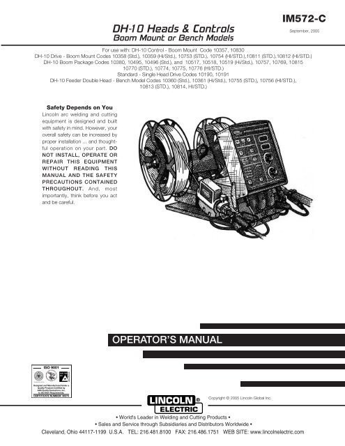
A-2GENERAL DESCRIPTIONINSTALLATIONAVAILABLE MODELS:A-2The <strong>DH</strong>-<strong>10</strong> is a modular line of 42VAC input dual head 4-rollwire feeders. A single control with dual procedure presettabilityof wire feed speed (in IPM or M/min) and arc voltagefor each head is used with a single DC welding powersource.The <strong>DH</strong>-<strong>10</strong> models have controls providing keypad orremote selectability of wire drive head, and either of two procedurespreset independently for each head.The units offer 4 independently selectable gun triggermodes for each head procedure; cold feed, 2 step and 4-step trigger and spot weld mode.Also, 4 selectable, presettable timers for each head procedure;preflow, postflow, burnback and spot weld time.Arc starting can be optimized for each head procedure with5 selectable wire feed acceleration rates, and independentcontrol of slower run-in procedure.A gas purge key is provided, as well as cold feed forwardand reverse keys with independently adjustable forwardfeed speed setting.All of these features are selected with a tactile-feel keypad,and are set independently for each head using one of tworotating knob encoders, setting levels are displayed on oneof two digital LED displays.The <strong>DH</strong> Wire Drive assemblies include two heavy dutyheads with externally changeable gear ratio and 4 driven rolldrives housed together in a single combination mountingand connection box. Gun adapters are available to permituse with a variety of standard welding guns.The <strong>DH</strong>-<strong>10</strong> Wire Feeder system is available configured inboth Bench and Boom models.Bench Models consists of a <strong>DH</strong>-<strong>10</strong> control and a <strong>DH</strong>double header wire drive assembly premounted on aplatform with a dual 2" (50.8mm) O.D. spindle mounting.Boom Models consist of a <strong>DH</strong>-<strong>10</strong> control and a choice ofwire drives designed to be mounted separately and joinedby available head to control cable assemblies.The head to control cable assemblies are available intwo types; one control cable is required for each head:K1785-”L”Includes a control cable with a 14-pinms style connection on each end, anda 3/0 weld cable. Available in lengths“L” of 12, 16 or 25 ft. (3.6, 4.9 or 7.6m) for recommended boom lengths of8-9 ft, <strong>10</strong>-12 ft or 16-18 ft. respectively.(2.4-2.7m, 3.0-3.7m or 4.9-5.5m).The <strong>DH</strong>-<strong>10</strong> boom packages are available in standardpackages as follows:K1521 -1 includes:<strong>DH</strong>-<strong>10</strong> Control (Sames as K1496-1)<strong>DH</strong>-<strong>10</strong> Std. Wire Drive Head (Same as K1497-1)16 ft. (4.9m) Control Cable (Same as K681-16)16 ft. (4.9m) Control and Weld Cable (Same as K1498-16)K1521 -4 includes:<strong>DH</strong>-<strong>10</strong> Control (Sames as K1496-1)<strong>DH</strong>-<strong>10</strong> Std.(Left)/Hi-Speed (Right) <strong>Heads</strong> (Same as K1497-2)16 ft. (4.9m) Control Cable (Same as K681-16)16 ft. (4.9m) Control and Weld Cable (Same as K1498-16)K1521 -7 includes:<strong>DH</strong>-<strong>10</strong> Control (Sames as K1496-2)<strong>DH</strong>-<strong>10</strong> Standard Wire Drive <strong>Heads</strong> (Same as K1497-3)16 ft. (4.9m) Control Cable (Same as K681-16)16 ft. (4.9m) Control and Weld Cable (Same as K1498-16)<strong>10</strong> ft. (3.5m) Control CableAlso there are four additional Zipline Boom Packages(K1521-2,-3,-5,&-6). For specifications see IM596-4.<strong>DH</strong>-<strong>10</strong>
A-3RECOMMENDEDAND EQUIPMENTPROCESSESThe <strong>DH</strong>-<strong>10</strong> Wire Feeder system is recommended foruse with solid wire gas-metal-arc or CV Submergedarc processes, as well as cored wire for Outershield,GMAW or Innershield processes.The wire type and size range for the wire drive used,and gear ratio change selected, are given in theSpecifications.Recommended power sources are <strong>Lincoln</strong> <strong>Electric</strong>Company constant voltage power sources with 42VAC auxiliary power and a 14-pin connector receptacle.At the time of printing these include: CV 250,CV300-I, CV-300, CV400-I, CV-400, CV500-I, DC-400, CV-655, Invertec V300-PRO, +V300-I, V350-PRO, DC-600, DC-650 PRO and DC-655.The DC-250, DC-600(Below Code <strong>10</strong>500), DC-<strong>10</strong>00and the Pulse Power 500 (Non-Pulsed CV mode only)may also be used with the <strong>DH</strong>-<strong>10</strong> if the optionalK1520-1 115V / 42V Transformer Kit is used.INSTALLATIONSAFETY PRECAUTIONSA-3ELECTRIC SHOCK cankill.• Turn the input power off at the power sourcedisconnect switch before attempting to connectthe input power to the <strong>DH</strong>-<strong>10</strong> Control.• Only qualified personnel should perform this installation.----------------------------------------------------------------------------------------INSTALLATION OF THE <strong>DH</strong>-<strong>10</strong>BOOM MOUNT WIRE FEEDERCOMPONENTSMounting the <strong>10</strong>-Series Wire Drive Unit(K1497-1, -2, -3,-4, K1563-1,-2,-3,-4)Mount the <strong>10</strong>-series wire drive unit to the boom orstructure using the four 5/16-18 threaded mountingholes located on the bottom of the <strong>DH</strong> drive connectionbox. See Figure A.1 for the size and location ofthe mounting holes. The feed plate assembly is electrically"hot" when the gun trigger is pressed.Therefore, make certain the feed plate does not comein contact with the structure on which the unit ismounted.The wire drive unit should be mounted so that thedrive rolls are in a vertical plane so dirt will not collectin the drive roll area. Pivot the feed plate so it willpoint down at an angle so the wire feed gun cable willnot be bent sharply as it comes from the unit. See“Procedure for setting angle of Feed Plate” in theOPERATION section of this manual.<strong>DH</strong>-<strong>10</strong>
A-4INSTALLATIONA-45/16-18 THREAD 2.25CLEARANCEFOR 1/4 BOLT<strong>10</strong>.50.506.0011.0014.0012.7513.75<strong>10</strong>.003.00BOTTOM FRONTFEED PLATEDOOR OPENCLEARANCEFOR 1/4 BOLTFIGURE A.1Mounting Synergic 7F Wire Drive Unit(K679-1 or -2)Mount the wire feed unit by means of the insulatedmounting bracket attached to the bottom of the gearbox.Reference L9777 (included with Drive unit) to find thesize and location of the mounting holes. The gearboxassembly is electrically “hot” when the gun trigger ispressed. Therefore, make certain the gearbox does notcome in contact with the structure on which the unit ismounted.The wire feed unit should be mounted so that the driverolls are in a vertical plane so dirt will not collect in thedrive roll area. Position the mechanism so it will pointdown at about a 45° angle so the wire feed gun cable willnot be bent sharply as it comes from the unit.Note: The K1496-1 control box must be used with theK679 drives.Mounting the <strong>DH</strong>-<strong>10</strong> Control Box (K1496-1,-2)The same control box is used for both a <strong>DH</strong> doubleheader drive, or up to two single head drives. The backplate of the control box has two keyhole slots and onebottom slot for mounting. See Figure A.2 for the sizeand location of these slots. Mount the box at some convenientlocation close to the wire drive unit which willenable the desired control cable to reach between thecontrol box and the wire drive unit.a) Drill the required holes in the mounting surface,partially install 1/4-20 screws.b) Mount the box.c) Tighten the screws.<strong>10</strong>.5018.505.002.6314.502.635.25FIGURE A.2Connecting Wire Drive Unit to Control BoxOne head to control cable assembly is required for eachhead being used; however, only one electrode cable isrequired if an electrode cable jumper (provided) is connectedbetween the two heads. The Head to Controlcable assemblies are available in two types:K1785-"L" -Includes a control cable with 14-pin Ms-styleconnectors on each end, and a 3/0 weldcable (rated 600 amps, 60% duty cycle) toroute between the wire drive and the controlbox. Available in lengths of 12 ft. (3.6m), 16ft. (4.9 m) and 25 ft. (7.6 m).a) Making certain the cables are protected from anysharp corners which may damage their jackets,mount the cable assembly along the boom so the endwith the female MS-style connector pins is at the wirefeed unit.b) Connect the 14-socket cable connectors to the matingreceptacles on the back of the wire feed unit connectionbox. Feeder Head 1 uses the left receptacle andFeeder Head 2 uses the right receptacle, when facingthe front of the wire drive.c) At the same end, connect the electrode lead to the1/2" connection bolt on the front of the left wire drivehead feed plate. If only one electrode cable is beingused, comparable size electrode cable jumper (provided)must be connected between the two heads.d) At the control box end, connect the 14 pin connectorsof the cables to the mating receptacles on the bottomof the control box. Feeder Head 1 should be connectedto the left receptacle and Feeder Head 2 should beconnected to the right receptacle, when facing thefront of the control box.<strong>DH</strong>-<strong>10</strong>e) At the control box current sensor, slip the cover boxup off the sensor and connect the electrode cable(s)to the top bolt connection.
A-5Electrode RoutingThe electrode supply may be either from reels, Readi-Reels, spools, or bulk packaged drums or reels.Observe the following precautions:INSTALLATIONA-5a) Loosen the clamping collar screw using a3/16" Allen wrench. The clamping collarscrew is accessed from the bottom of thefeedplate. It is the screw which is perpendicularto the feeding direction.a) The electrode must be routed to the wire drive unitso that the bends in the wire are at a minimum,and also that the force required to pull the wirefrom the reel into the wire drive unit is kept at aminimum.b) The electrode is "hot" when the gun trigger ispressed and must be insulated from the boom andstructure.c) If more than one wire feed unit shares the sameboom and are not sharing the some power sourceoutput stud, their wire and reels must be insulatedfrom each other as well as insulated from theirmounting structure.WIRE DRIVE SPEED RANGESELECTIONThe rated speed and wire size range for each wiredrive head is shown in the SPECIFICATIONS in thefront of this section.Control Speed Range SettingThe speed range is set up to match each wire feedhead connected to the <strong>DH</strong>-<strong>10</strong> control by properly settingthe switch (S2) code on the control board insidethe control box. See OPERATION “Setting the DIPSwitches” for setting instructions.<strong>10</strong>-Series (<strong>DH</strong>) Wire Drive Ratio SelectionThe Double Head type drives include two externalgear sizes; a 1"(25.4mm) dia. gear and a 1-1/2"(38.1mm) dia. gear. The smaller gear provides thelow speed range ratio, and the larger gear providesthe high speed range ratio per the SPECIFICATIONSin the front of this section.The following procedure is for changing ratio of the<strong>DH</strong> drive:1) Pull open the Pressure Door.2) Remove the Phillips head screw retaining the piniongear to be changed and remove the gear. If thegear is not easily accessible or difficult to remove,remove the feedplate from the gearbox. To removefeedplate:b) Loosen the retaining screw, which is alsoaccessed from bottom of feeder, using a3/16" Allen wrench. Continue to loosenthe screw until the feedplate can be easilypulled off of the wire feeder.3) Loosen, but do not remove, the screw on the lowerright face of the feedplate with a 3/16" Allenwrench.4) Remove the screw on the left face of the feedplate.If changing from high speed (larger gear) to lowspeed (smaller gear), line the lower hole on the leftface of the feedplate with the threads on theclamping collar. Line the upper hole with thethreads to install larger gear for high speed feeder.If feedplate does not rotate to allow holes to lineup, further loosen the screw on right face of feedplate.5) Install gear onto output shaft and secure with flatwasher, lock washer, and Phillips head screwwhich were previously removed.6) Tighten the screw on lower right face of feedplate.7) Install gear onto output shaft and secure with flatwasher, lock washer, and Phillips head screwwhich were previously removed.8) Re-attach feedplate to wire feeder if removed inStep 2.9) Feedplate will be rotated out-of-position due to thegear change. To re-adjust angle of feedplate:a) Loosen the clamping collar using a 3/16"Allen wrench. The clamping collar screw isaccessed from the bottom of the feedplate.It is the screw which is perpendicular to thefeeding direction.b) Rotate feedplate to the desired angle andtighten clamping collar screw.<strong>10</strong>) Make sure to properly set the switch (S2) code onthe control board inside the control box for thenew gear size installed. See OPERATION“Setting the DIP Switches” for setting instructions.<strong>DH</strong>-<strong>10</strong>
A-6WIRE FEED DRIVE ROLL KITSNOTE: The maximum rated solid and cored wiresizes for each wire drive head and selecteddrive ratio is shown on the SPECIFICATIONSin the front of this section.INSTALLATIONA-6TO SET IDLE ROLL PRESSURE, see “Idle RollPressure Setting” in OPERATION.<strong>DH</strong> Drive Roll Kit Installation (KP1505 andKP1507)1) Turn OFF Welding Power Source.The electrode sizes that can be fed with each roll andguide tube are stenciled on each part. Check the kitfor proper components.Synergic 7F Drives (K679) use 4-Roll drive roll kitswith 2 driven rolls, per Table C.1 in ACCESSORIES.These kits are common with those used for the 4-RollLN-7 GMA and LN-9 GMA <strong>Lincoln</strong> Wire Feeders, butare not common with those used with the <strong>DH</strong> wiredrive units. Installation instructions are included withthe kits.2) Pull open Pressure Door to expose rolls and wireguides.3) Remove Outer Wire Guide by turning knurledthumb screws to unscrew from Feedplate.4) Remove drive rolls, if any are installed, by pullingstraight off shaft. Remove inner guide.5) Insert Inner Wire Guide, groove side out, over thetwo locating pins in the feedplate.Series Double Head Drives use 4-Roll drive roll kitswith 4 driven rolls, per Table C1 in ACCESSORIES.Each head requires a separate drive roll kit.PROCEDURE TO INSTALL DRIVEROLL AND WIRE GUIDESWARNINGELECTRIC SHOCK can kill.• Do not touch electrically live parts suchas output terminals or internal wiring.• When inching with gun trigger, electrode anddrive mechanism are “hot” to work andground and could remain energized severalseconds after the gun trigger is released.• Turn OFF input power at welding powersource before installation or changingdrive roll and/or guide tubes.• Welding power source must be connectedto system ground per the National<strong>Electric</strong>al Code or any applicable localcodes.• Only qualified personnel shouldperform this installation.Observe all additional Safety Guidelines detailedthroughout this manual.<strong>DH</strong>-<strong>10</strong>
A-76) Install each drive roll by pushing over shaft until itbutts up against locating shoulder on the drive rollshaft. (Do not exceed maximum wire size rating ofthe wire drive).7) Install Outer Wire Guide by sliding over locatingpins and tightening in place.8) Engage upper drive rolls if they are in the “open”position and close Pressure Door.TO SET IDLE ROLL PRESSURE, see “Idle RollPressure Setting” in OPERATION.GUN AND CABLE ASSEMBLIESWITH STANDARD CONNECTIONThe <strong>DH</strong> Wire Drive <strong>Heads</strong> each require a K1500 GunAdapter installed See “Gun Adapters” in ACCES-SORIES section.NoteNote: When a K489-7 Fast-Mate is used a K1500 gunadapter is not needed.<strong>10</strong>-SeriesGMAW GUNSDrive Gun Adapter MAGNUM 200,300,400 MAGNUM 550K1500-1 K466-1 (STD)* K613-1 (STD)*K1500-2 K466-<strong>10</strong> (Tweco 4) ◊ -------------------------K1500-3 ----------------------- K613-7(Tweco 4) ◊*Recommended Magnum Connection Kit for K679 Synergic 7F.◊Recommended Magnum Connection Kit for <strong>10</strong>-Series Wire Drives.INSTALLATIONGun Cable Connection with StandardConnectionA-71. Check that the drive rolls and guide tubes areproper for the electrode size and type being used.If necessary, change them per “Wire Drive RollKits” in this section.2. Lay the cable out straight. Insert the connector onthe welding conductor cable into the brass conductorblock on the front of the wire drive head. Makesure it is all the way in and tighten the hand clamp.Keep this connection clean and bright. Connect thetrigger control cable polarized plug into the mating5 cavity receptacle on the front of the wire driveunit.3. For GMA Gun Cables with separate gas fitting (<strong>DH</strong>Drive using K1500-1 Gun Adapter), connect the3/16" I.D. gas hose from the wire drive unit to thegun cable barbed fitting.GUN AND CABLE ASSEMBLIESWITH FAST-MATE CONNECTION(Requires K489-2 or K489-7 Fast Mate Adapter Kitused with the <strong>DH</strong> K1500-1 Gun Adapter)GMAW GunsAn expanding line of Magnum gun and cable assembliesare available to allow welding with solid andcored electrodes using the GMAW process. See theappropriate Magnum literature for descriptions of the200 to 550 ampere air cooled gun and cables that areavailable. Gun cable lengths range from <strong>10</strong> ft. (3.0 m)to 25 ft. (7.6 m) and feed electrode sizes .025" (0.6mm) to 3/32" (2.4 mm). The entire line of MagnumFast-Mate gun and cable assemblies can also beused by installing a K489-2 Fast-Mate adapter kit.See “Gun and Cable Assemblies with Fast-MateConnection” in this section for details.Innershield GunsK126 and K115 gun and cable assemblies are availableto allow welding with Innershield electrodes. Guncable lengths range from <strong>10</strong> ft. (3.0 m) to 15 ft. (4.5 m)The 350 ampere K126 will feed electrode sizes .062(1.6 mm) to 3/32" (2.4 mm). The 450 ampere K115will feed 5/64" (2.0 mm) to 3/32" (2.4 mm) electrode.Three smoke extraction gun and cable assemblies areavailable, 250 ampere K309, 350 ampere K206 andthe 500 ampere K289. All gun cable lengths are 15 ft.(4.5 m). These guns will feed electrode sizes .062"(1.6 mm) to 3/32" (2.4 mm) and require the use of theK184 vacuum unit for use with the <strong>DH</strong>-<strong>10</strong>.GMAW GunsAn expanding line of Magnum Fast-Mate air cooledand water cooled gun and cable assemblies are availableto allow welding with solid and cored electrodesusing the GMAW process. See the appropriateMagnum literature for descriptions of the 200 to 400ampere air cooled gun and cables that are availableas well as the Magnum “Super Cool” 450 amperewater cooled gun and cable. Gun cable lengths rangefrom <strong>10</strong> ft. (3.0 m) to 25 ft. (7.6 m) and feed electrodesizes .025" (0.6 mm) to 5/64" (20 mm).An expanding line of Magnum X-Tractor gun andcable assemblies provides fume extraction capabilityfor welding with solid and cored electrodes using theGMAW process. See the appropriate Magnum literaturefor descriptions of the 250 to 400 ampere aircooled gun and cables that are available. Gun cablelengths range from <strong>10</strong> ft. (3.0 m) to 15 ft. (4.5 m) andfeed electrode sizes .035" (0.9 mm) to 1/16" (1.6 mm).These guns require the use of either the K173-1 orK184* vacuum units.*Requires S14927-8 connector hose and an S20591hose adapter.<strong>DH</strong>-<strong>10</strong>
A-9INSTALLATIONELECTRICAL INSTALLATIONWORK CABLEA-9WARNINGELECTRIC SHOCK can kill.• Do not touch electrically live parts suchas output terminals or internal wiring.• When inching with gun trigger, electrode anddrive mechanism are “hot” to work andground and could remain energized severalseconds after the gun trigger is released.• Turn OFF input power at welding powersource before installation or changingdrive roll and/or guide tubes.• Welding power source must be connectedto system ground per the National<strong>Electric</strong>al Code or any applicable localcodes.• Only qualified personnel shouldperform this installation.Connect a work lead of sufficient size and length (perthe following table) between the proper output terminalon the power source and the work. Be sure theconnection to the work makes tight metal-to-metalelectrical contact.Current60% DutyCycle400 Amps500 Amps600 AmpsCopper Work Cable Size, AWGUp to <strong>10</strong>0 ft Length (30m)2/0 (67 mm 2 )3/0 (85 mm 2 )3/0 (85 mm 2 )Observe all additional Safety Guidelines detailed throughout this manual.INPUT CABLE: <strong>DH</strong>-<strong>10</strong> CONTROL TOPOWER SOURCEAvailable Cable Assemblies:K1501-<strong>10</strong> (Control Cable Only) Consists of a 9-conductorcontrol cable with a 14-pin control cable plug,without electrode cable, and is available in lengths of<strong>10</strong> ft. (3 m).K1797-25 Consists of a 14-conductor control cableextension 25’(7.6m) in length.K1797-50 Consists of a 14-conductor control cableextension 50’(15.24m) in length.With input power disconnected from the powersource, install the input cable per the following:1) Connect the end of the control cable with the 14-pin cable plug to the mating receptacle on thepower source.2) Connect the electrode lead to the power sourceoutput terminal of the desired polarity.3) Connect the 9-socket plug of the control cable tothe mating receptacle on the bottom of the <strong>DH</strong>-<strong>10</strong>control box.4) Slip the current sensor cover off enough to exposethe input connector stud. Connect the electrodecable from the power source to this stud with thenut provided, then close the current sensor cover.<strong>DH</strong>-<strong>10</strong>
A-<strong>10</strong>OPTIONAL FEATURESINSTALLATIONK1501-<strong>10</strong>, K1797-25 and K1797-50 Input CableAssembliesSee “<strong>Electric</strong>al Installation” for instructions.K1520-1 115V/42V Transformer Kit. Required to use <strong>DH</strong>-<strong>10</strong> with <strong>Lincoln</strong> Power Sources without 42VAC auxiliary anda 14-pin connector receptacle. These power sources includethe DC-250, DC-600, DC-<strong>10</strong>00 and Pulse Power 500. Alsocan be used with older DC-400 models. Mounts on powersource per installation instructions included with the kit.Spindle AdaptersK162H Spindle for boom mounting Readi-Reels and 2"(51 mm) I.D. spools with 60 lb. (27.2 kg) capacity. Usermounted to appropriately prepared boom framework.Includes an easily adjustable friction brake for control ofoverrun (Two 2" spindles standard on <strong>DH</strong>-<strong>10</strong> Bench models).When a 2" (51 mm) spindle is used with Readi-Reels, orcoils not on 12" (305 mm) O.D. spools, an adapter isrequired:INSTALLATIONA-<strong>10</strong>K1500-3 for Magnum 550 gun with K613-7 ConnectionKit. (Also Tweco 5).K1500-4 (Miller Connection) for any gun having anewer style miller connection. Install gun adaptersper the instructions shipped with the unit.Dual Procedure Switch OptionsK683-1 Dual Procedure Switch (One per gun) - RequiresK686-2 Adapter for <strong>DH</strong>-<strong>10</strong>. Kit includes gun switch, andmountings for <strong>Lincoln</strong> Innershield and Magnum guns, with15 ft. (4.5 m) control cable and 3-pin plug. K686-2 Adapterpermits 3-pin plug and 5-pin gun trigger plug to be connectedto <strong>DH</strong>-<strong>10</strong> 5-pin Trigger/Dual Procedure receptacle.Connect the 5-pin plug of the K686-2 Adapter to the <strong>DH</strong>-<strong>10</strong>Wire Feeder Trigger/Dual Procedure 5-socket receptacle.The 3-pin plug of the K683-1 Dual Procedure switch connectsto the 3-socket receptacle of the Adapter, and the 5-pin plug of the welding un connects to the 5-socket receptacleof the Adapter.K683-3 Dual Procedure Switch (One per gun) Kit includesgun switch, and mountings for <strong>Lincoln</strong> Innershield andMagnum guns, with 15 ft. (4.5m) control cable and 5-pinplug with two leads to connect to gun trigger.Coil AdapterK1504-1 Permits 50 lb to 60 lb (22.7-27.2 Kg.) coils tobe mounted on 2" (51 mm) O.D. spindles.K435 Permits 14 lb. (6 kg) Innershield coils to be mountedon 2" (51 mm) O.D. spindles.K468 Permits 8" (203 mm) O.D. spools to be mounted on2" (51 mm) O.D. spindles.Readi-Reel AdaptersK363P Adapts <strong>Lincoln</strong> Readi-Reel coils of electrode 30 lb.(14 kg) and 22 lb. (<strong>10</strong> kg) to a 2" (51 mm) spindle. Durablemolded plastic one piece construction. Designed for easyloading; adapter remains on spindle for quick changeover.K438 Adapts <strong>Lincoln</strong> Readi-Reel coils of electrode 50-60lb. (22.7-27.2 kg) to a 2" (51 mm) spindle.Gun Adapters (For <strong>10</strong>-Series Wire Drive <strong>Heads</strong>)Adapts <strong>DH</strong> heads for desired gun connectionK489-7 for Fast-Mate (or European style) gun connections,including Dual Schedule Fast-Mate guns.Connect the 5-pin plug of the K683-3 Dual procedureSwitch to the <strong>DH</strong>-<strong>10</strong> Wire Feeder Trigger/Dual Procedure5-socket receptacle.The two lead plug cord extending out of the 5-pin plug ofthe Dual Procedure switch is to be connected to the twotrigger leads of the welding gun per the instructionsshipped with the kit.Using Dual Procedure with Fast-Mate gunsThere are a number of different options available forusing dual procedure with Fast-Mate guns. Theseconfigurations are outlined below along with any additionalrequired equipment.Using Dual Schedule with Fast-Mate guns on -<strong>10</strong>Series FeedersConfiguration 1K489-7 Dual Schedule Fast-Mate adapterK575-* Magnum 400 DS/FM gun(or competitive DS/FM gun)K1500-1 for standard <strong>Lincoln</strong> Innershield gun connection,or with Fast-Mate guns with K489-2 Fast-Mate AdapterKit. Also for Magnum 200/300/400 with K466-1 ConnectionKit or Magnum 550 with K613-1.K1500-2 for Magnum 200/300/400 gun with K466-<strong>10</strong>Connection Kit. (Also Tweco 4).<strong>DH</strong>-<strong>10</strong>
A-11Configuration 2K489-7 Dual Schedule Fast-Mate adapterK683-1 Dual Procedure Switch (3 pin)K686-2 “Y” adapter (3 pin +5 pin to 5 pin)* Non-DS Fast-Mate gun (Magnum 450WC, Magnum 200, Magnum300, Magnum 400 and othersK590-6 Water Connection Kit (For <strong>DH</strong> Drive Only)Install per the instructions shipped with the kit. One used pergun.K659-1 Gas Guard Regulator (One used per gun)Adjustable flow regulator with removable adjustor keyfor CO2 and Argon blend gases. Mounts onto feederinlet, and reduces gas waste and arc start “blow” byreducing surge caused by excess pressure in supplyhose.Install the 5/8-18 male outlet of the regulator to one, orboth of the 5/8-18 female gas inlets on the back panelof the wire drive. Secure fitting with flow adjuster keyat top. Attach gas supply to 5/8-18 female inlet of regulatorper Section 1.8.K1449-1 Dual Procedure Remote ControlProvides remote rotating knob encoder control of WireFeed Speed and Voltage, along with a dual procedureselector switch, when the remote control is connectedand REMOTE is selected by the <strong>DH</strong>-<strong>10</strong> Procedurekey. The <strong>DH</strong>-<strong>10</strong> A or B procedure light will also be onto indicate which procedure is selected by the remotecontrol.The 4-pin plug of the remote control connects to themating receptacle on the bottom of the <strong>DH</strong>-<strong>10</strong> Controlbox. Only one remote is used with a <strong>DH</strong>-<strong>10</strong> control.The K1450-”L” Extension cable is used to extend the16 ft (5m) cable attached to the remote control.Lengths “L” are available to match the Length of thecontrol to boom mount wire drive cable being used..INSTALLATIONA-11K1558-1 Remote Switch Interface Module, can beused with the <strong>DH</strong>-<strong>10</strong>, using a G3041-2 (or higher)Control Board.The module provides for user interface connection ofan external switch (flow switch, etc) which must beclosed to enable the feeder welding operation. Also,the module provides for interface connection of externalequipment (fume extractor, etc.) To the module’sisolated relay contacts which actuate when the feederwelding gas solenoid is activated (representing weldingoperation in process)When used with the <strong>DH</strong>-<strong>10</strong>, the module providesthese input and output switch function connectionsindependently for each head operation.This module is necessary when using the K1536-1waterflow sense kit with the <strong>DH</strong>-<strong>10</strong>.BOOM AND BENCH CONVERSIONSThe modular design of these feeders allows them tobe converted from bench to boom models or viseversa. Some additional parts are required to make thisconversion.Materials Required for bench to boomconversion:S13<strong>10</strong>0-197 Plug and Lead assembly, allows a controlcable to connect from control box to the wire drive.(A quantity of 2 for the <strong>DH</strong>-<strong>10</strong> only.) Installs in rear ofwire drive.G2868 Mounting Bracket, allows reed switch to berelocated to control box.K1498-16 AND K1498-25 Control Box to Wire Drive,Control cable and power cable from control box towire drive. (A quantity of 2 control cables needed forthe <strong>DH</strong>-<strong>10</strong> only.)Materials Required for boom to benchconversion:L<strong>10</strong>215 Wire Reel Stand, for <strong>DH</strong>-<strong>10</strong> only, mount thereed switch onto the reel stand.S22777 Control Box Support Bracket, to mount thecontrol box onto the wire drive.S13<strong>10</strong>0-198 Plug and Lead Assembly, electrical connectionbetween control box and wire drive.(A quantity of 2 for the <strong>DH</strong>-<strong>10</strong> only.)<strong>DH</strong>-<strong>10</strong>
B-1OPERATING INSTRUCTIONSSafety PrecautionsWARNINGELECTRIC SHOCK can kill.• Do not touch electrically live parts suchas output terminals or internal wiring.• Unless using cold feed feature when inchingwith gun trigger, electrode and drive mechanismare “hot” to work and ground and couldremain energized several seconds after thegun trigger is released.• Turn OFF input power at welding powersource before Control switch setup orchanging drive roll and/or guide tubes.• Welding power source must be connectedto system ground per the National<strong>Electric</strong>al Code or any applicable localcodes.• Only qualified personnel shouldoperate this Equipment.Observe all additional Safety Guidelines detailedthroughout this manual.Duty CycleThe <strong>DH</strong>-<strong>10</strong> models are rated at 60% duty cycle * for amaximum current of 600 amps.* Based on a <strong>10</strong> minute time period (6 minutes on, and 4 minutes off).<strong>DH</strong>-<strong>10</strong> CONTROL SWITCH SETUPInitial set up of the <strong>DH</strong>-<strong>10</strong> control for the system componentsbeing used and for general operator preferencesis done using a pair of 8-pole DIP switcheslocated inside the <strong>DH</strong>-<strong>10</strong> control box.Setup DIP Switch Access1) Shut off the input power to the <strong>DH</strong>-<strong>10</strong> control byturning off the power at the welding power sourceit is connected to.2) Remove the two screws on the top of the <strong>DH</strong>-<strong>10</strong>control box door and swing the door down toopen.3) Locate the two 8-pole DIP switches, near the topleft corner of the <strong>DH</strong>-<strong>10</strong> Control P.C. board,labeled S1 and S2.4) Switch settings are only programmed during inputpower-up restoration.OPERATIONSetting the DIP SwitchesB-1The DIP switches are each labeled with an “ON”arrow showing the on direction for each of the 8 individualswitches in each DIP switch (S1 and S2). Thefunctions of these switches are also labeled and setas described below:Pwr SourcesM 4ON 1 2 3 4 5 6 7 8S1SecurityS1Wire Drive Head SelectionThe <strong>DH</strong>-<strong>10</strong> control is set up for proper presettablewire feed speed by setting S2 DIP switches (1 to 4) forHead 1 (left side head) and DIP switches (5 to 8) forHead 2 (right side head) as appropriate per the followingexamples for the head specification and <strong>DH</strong> driveexternal gear selection being used:NOTE: Set the proper 4 switches labelled for Head 1(Left Head) or Head 2 (Right Head) as appropriate forthe way that Head is being used.<strong>DH</strong>-<strong>10</strong> HEADS:For K1497-1,-3 (<strong>DH</strong>-<strong>10</strong> Boom) or K1499-1, -3 (<strong>DH</strong>-<strong>10</strong> Bench) with 35-500 IPM (0.89-12.7 m/m) LowSpeed Ratio set S2 DIP Switches as follows:ONS2HEAD 1For K1497-1,-3 (<strong>DH</strong>-<strong>10</strong> Boom) or K1499-1, -3 (<strong>DH</strong>-<strong>10</strong> Bench) with 50-750 IPM (1.25-19.0 m/m) HighSpeed Ratio set S2 DIP Switch as follows: (initialfactory setting) HEAD 1 HEAD 2ONS2For K1497-2,-4 (<strong>DH</strong>-<strong>10</strong> Boom) or K1499-2, -4 (<strong>DH</strong>-<strong>10</strong> Bench) with Left Head 35-500 IPM (0.89-12.7m/m) & Right Head 55-825 IPM (1.40-21.0 m/m)Low Speed Ratio set S2 DIP Switch as follows:ONS2HEAD 1For K1497-2,-4 (<strong>DH</strong>-<strong>10</strong> Boom) or K1499-2, -4 (<strong>DH</strong>-<strong>10</strong> Bench) with Left Head 50-750 IPM (1.25-19.0m/m) & Right Head 80-1250 IPM (2.00-31.8 m/m)High Speed Ratio set S2 DIP Switch as follows: (initialfactory setting)ONS2HEAD 21 2 3 4 5 6 7 81 2 3 4 5 6 7 8HEAD 11 2 3 4 5 6 7 8HEAD 1HEAD 2HEAD 2HEAD 21 2 3 4 5 6 7 8S2S2S2S2ON1 2 3 4 5 6 7 8S2S2<strong>DH</strong>-<strong>10</strong>
B-2OPERATIONB-2SINGLE HEADS:For K1563-1,-3 with 35-500 IPM (0.89-12.7 m/m)Low Speed Ratio set S2 DIP Switches as follows:For K679-1 with 50-770 IPM (1.27-19.5 m/m) LowSpeed Ratio set S2 DIP Switch as follows:ON1 2 3 4 5 6 7 8S2ON1 2 3 4 5 6 7 8S2S2S2For K1563-1,-3 with 50-750 IPM (1.25-19.0 m/m)High Speed Ratio set S2 DIP Switch as follows: (initialfactory setting)For K679-2 with 80-1200 IPM (2.00-30.5 m/m) HighSpeed Ratio set S2 DIP Switch as follows:ON1 2 3 4 5 6 7 8S2S2ONS21 2 3 4 5 6 7 8For K1563-2,-4 with 55-825 IPM (1.40-21.0 m/m)Low Speed Ratio set S2 DIP Switch as follows:S2Note: The K679-1 and -2 require the K1562-1 controlbox. Any single drive may be connected to the Head 1or Head 2 connector. Both settings are configured thesame way.ON1 2 3 4 5 6 7 8S2S2For K1563-2,-4 80-1250 IPM(2.00-31.8 m/m) High Speed Ratio set S2 DIPSwitch as follows: (initial factory setting)ON1 2 3 4 5 6 7 8S2S2<strong>DH</strong>-<strong>10</strong>
B-3Welding Power Source SelectionThe <strong>DH</strong>-<strong>10</strong> Control is set up for proper presettableweld voltage control by setting S1 DIP switches (1 to4) as appropriate per the following information for thewelding power source being used:CV-250/CV 300-I:ONPwr SourcesM 41 2 3 4 5 6 7 8SecurityS1OPERATIONV300 PRO:ONS1V350 PRO and V450-PROONPwr SourcesM 41 2 3 4 5 6 7 8Pwr Sources1 2 3 4 5 6 7 8SecurityS1S1B-3S1CV-300/CV 400-I:Pwr SourcesM 4ON 1 2 3 4 5 6 7 8SecurityS1S1"Other: Power Source Independent" power sourceselection dip switch setting:CV-400/CV 500-I:CV-655 / DC-655: (initial factory setting)DC-250:DC-400:DC-600:DC-650 PRO:DC-<strong>10</strong>00:S1Pulse Power 500:SecurityPwr SourcesM 4ON 1 2 3 4 5 6 7 8 S1S1Pwr SourcesSecurityM 4ON 1 2 3 4 5 6 7 8 S1S1Pwr SourcesSecurityM 4ON 1 2 3 4 5 6 7 8 S1S1Pwr SourcesSecurityM 4ON 1 2 3 4 5 6 7 8 S1S1Pwr SourcesSecurityM 4ON 1 2 3 4 5 6 7 8 S1S1SecurityPwr SourcesM 4ON 1 2 3 4 5 6 7 8 S1S1Pwr SourcesSecurityM 4ON 1 2 3 4 5 6 7 8 S1S1Pwr SourcesSecurityM 4ONS11 2 3 4 5 6 7 8 S1<strong>DH</strong>-<strong>10</strong>ONS1Pwr SourcesSecuritySet the DIP switches all off, as shown, for all otherpower sources which can be controlled with a <strong>10</strong>KΩpotentiometer circuit.The <strong>DH</strong>-<strong>10</strong> is designed to work with the following<strong>Lincoln</strong> <strong>Electric</strong> power sources: CV250, CV300-I,CV300, CV400-I, CV400, CV500-I, CV655, DC250,DC400, DC600, DC650 PRO, DC<strong>10</strong>00, Pulse Power500 (non-pulse CV modes only), the V300 PRO, V350PRO, and the DC655. To use the <strong>DH</strong>-<strong>10</strong> with otherpower sources, the "Other: Power SourceIndependent" power source selection dip switch setting(S1 switches 1-4 in the OFF position) may beused. All <strong>DH</strong>-<strong>10</strong> features operate as described elsewherein this manual except for the following differences:1. Instead of displaying a preset value in volts, the topdisplay will show a number from “0.00” to “<strong>10</strong>.00” inincrements of “0.02”. The number can be used forsetting run-in “voltage” as well as “weld preset voltage”.When the trigger is closed or while welding,the top display will display actual arc voltage. Thevoltage displayed while welding can be used todetermine the arc voltage to be expected for agiven number setting. Actual arc voltage displaywill still flash for 5 seconds after a weld has beencompleted.2. If a loss of arc voltage occurs, wire will NOT stopfeeding. The Loss of Voltage Sense Shutdown featureis disabled to permit the use of the <strong>DH</strong>-<strong>10</strong> withpower source connections that do not connect thework voltage back to the <strong>DH</strong>-<strong>10</strong> through the inputpower cable. The actual weld voltage while weldingwill NOT properly be shown on the top display if thework voltage is not available to the <strong>DH</strong>-<strong>10</strong> throughthe input power cable.M 41 2 3 4 5 6 7 8S1
B-4Metric/English Wire Feed Speed DisplaySelectionThe <strong>DH</strong>-<strong>10</strong> Control is set up for Wire Feed Speed displayin Metric units (m/min.) or English units (IPM) bysetting S1 DIP Switch 6 (Labeled “M”):S1 switch 6 OFF = IPM (as shipped)ONS1Pwr SourcesM 41 2 3 4 5 6 7 8SecurityS1OPERATIONB-4S1 switch 7 ON = 4-Step without current interlockoperation:ONS1Pwr Sources1) Closing Trigger initiates gas flow.2) Opening Trigger initiates gas preflow timer followedby Run-in speed and strike voltage until arcstrike initiates welding. (Trigger is released beforearc is struck, but once established breaking arcstops the feeder operation).M 41 2 3 4 5 6 7 8SecurityS1S1 switch 6 ON = m/minPwr SourcesM 4ON 1 2 3 4 5 6 7 8S1SecurityS13) Reclosing Trigger stops wire feed and initiatesburnback time, then gas postflow time.4) Reopening Trigger stops gas flow if, or when, postflowtime is over.Low Security Mode Selection4-Step Trigger Mode Operation SelectionThe <strong>DH</strong>-<strong>10</strong> Control is set up for 4-Step Trigger modeoperation with or without weld current interlock by settingS1 DIP switch 7 (Labeled “4”).When 4-Step trigger mode is selected on the <strong>DH</strong>-<strong>10</strong>keypad (See Keypad and Display Operation in thissection) S1 DIP switch setting determines the 4-steptrigger operation:S1 switch 7 OFF = 4-Step with current interlockoperation: (As shipped)ONS1Pwr SourcesSecurity1) Closing Trigger initiates gas preflow time followedby Run-in speed and strike voltage until arc strikeinitiates welding.2) Opening Trigger after welding arc is establishedcontinues welding with weld current interlock.(Breaking arc stops the feeder operation).3) Reclosing Trigger continues welding but shuts offcurrent interlock function.4) Reopening Trigger stops wire feed and initiatesburnback time, then gas postflow time.M 41 2 3 4 5 6 7 8S1The <strong>DH</strong>-<strong>10</strong> Control is set up for Low Security Mode(See “Security Modes” in this section) by setting S1DIP Switch 8 (Labeled “S”):S1 switch 8 ON = Low Security mode ONONS1S1 switch 8 OFF = Low Security mode OFF (asshipped)SecurityONS1Pwr SourcesSecurityNOTE: High Security mode must be OFF for LowSecurity mode to function.High Security Mode SelectionThe <strong>DH</strong>-<strong>10</strong> Control is set up for High Security Mode(See “Security Modes” in this section) by setting S1DIP Switch 5 (Not labeled):S1 switch 5 ON = High Security mode ONONS1S1 switch 5 OFF = High Security mode OFF (asshipped)ONM 41 2 3 4 5 6 7 8Pwr SourcesPwr SourcesM 41 2 3 4 5 6 7 8Pwr SourcesM 41 2 3 4 5 6 7 8M 41 2 3 4 5 6 7 8S1S1SecurityS1SecurityS1S1<strong>DH</strong>-<strong>10</strong>
RB-5OPERATIONKEYPAD AND DISPLAY OPERATION1LINCOLNCOLD FEEDFORWARDFEEDER2COLD FEEDREVERSEAGAS PURGEREMOTEPROCEDUREBVWFSB-5Dual procedure settings, including; trigger mode, coldfeed speed, Run-in and weld speed and voltage,timers and acceleration are automatically saved foreach feeder when power is removed. This featuredoes not require batteries and when power is restoredit will automatically return all settings to the state theywere in when power was removed. The operator mayoverwrite any or all of these settings following powerup recall.COLD FEEDVVOLTSOperation Keys12-STEP STD4-STEP LOCKSPOTPREFLOWSPOTBURNBACK2 POSTFLOWTRIGGERRUN-INVOLTS / WFSWIRE FEED SPEED1FEEDER2Feeder Lights - Indicate the wire feedhead selected for procedure, mode,timer and cold feed functions settings.The feeder may be selected by pressingthe Feeder select key, or by the lastfeeder gun trigger that was closed.TIMERTHE LINCOLN ELECTRIC COMPANYCONTROLCLEVELAND, OHIO U.S.A.Keypad and Display DescriptionKeypad - Eight key, membrane type with "snap" tactilefeel and embossed domes. Long life design.Spatter resistant surface.Displays - Two digital LED displays with .56" (14.2mm) character height. Top (3-1/2 digit) displaysPreset and Actual (while welding) arc voltage in voltswith (+) or (-) polarity indicators, and also displays alltimers in seconds. Bottom (4 digit) displays presetwire feed speed in IPM, or m/m, and accelerationselection.Indicator Lights - Extra bright red LEDs for viewingat almost any angle. Always indicate the feeder andprocedure selected, trigger mode being used andfunction or timer being displayed.Rotating Encoders - Knob controls increase ordecrease settings of volts and wire feed speed. (initiallyfactory set to minimum) Alternately, the topencoder adjusts timer settings and bottom selectsacceleration settings when selected for these parametersto be displayed.G3030A REMOTEPROCEDUREProcedure Lights - Indicate whichBprocedure (A or B) is selected for theselected feeder. A and B procedure forFeeder 1 is independently set from Aand B Procedure for Feeder 2. TheProcedure select key selects A or B, orif REMOTE Light is selected, the procedureselection light is controlled byconnection of an optional Dual Procedure gun switch(K683-1, -3) or Dual Procedure Remote Control(K1449-1).COLD FEEDFORWARDCold Feed Keys - energizethe wire feeder but not thepower source or gas solenoidvalve. Cold FeedForward speed is factoryset at 200 IPM, but is adjustable with WFS encoderknob and displayed on WFS display (with ”Cld” shownon the Voltage display) only while pressing Cold FeedForward, and the last speed set is stored in memoryfor the next cold feeding, unless changed in ColdFeed trigger mode (see following section). Cold FeedReverse retracts wire at a fixed 80 IPM speed which isnot adjustable.GAS PURGECOLD FEEDREVERSEGas Purge key - energizes the gassolenoid valve but not the wire feeder orpower source.Power-Down SavePower to the <strong>DH</strong>-<strong>10</strong> is supplied and controlled fromthe power source. The <strong>DH</strong>-<strong>10</strong> automatically sensesthe loss of power when the power source is turned off.<strong>DH</strong>-<strong>10</strong>
B-6Trigger Mode SelectionOPERATIONDisplay Control KeysB-6Trigger Mode Select keyCOLD FEED- enables operator toTRIGGER2-STEP STDchoose mode of operation4-STEP LOCKshown by the indicatorSPOTlights. Pressing key causesmode lights tosequence (top to bottom) starting from the currentindicated selection.Top Light - Indicates gun trigger has been selected toperform the Cold Feed Forward function in exactly thesame manner as Cold Feed Forward key (SeeOperation Keys - Cold Feed Keys) with the samememory stored adjustable speed setting, and “Cld”shown on the Voltage display.Second Light - indicates 2-step (standard) triggermode.1. Trigger closure energizes the solenoid valve,then the wire feeder and the power sourceafter Preflow time.2. Releasing the trigger turns off the wire feeder,then power source after burnback time andthen the gas solenoid valve after Postflow time.Third Light - indicates 4-step (lock) trigger mode.This mode may be selected to include or exclude weldcurrent interlock. (See “4-Step Trigger ModeOperation Selection” in this section for 4 step TriggerMode operation)Bottom Light - indicates Spot Weld Mode, which willonly light if a spot time is set (See “Display ControlKeys” in this section). If set to 0.0 seconds, spotmode light selection will be skipped. Trigger closureenergizes the gas solenoid valve, then wire feederand the power source. The spot timer starts whencurrent flows. The wire feeder and power source thensolenoid valve are all turned off when the spot ontimer times out even though the trigger is opened or isstill closed. Preflow/Postflow and burnback timers arealso functional in spot mode. (See “Display ControlKeys” in this section).TIMER Timer Select key - enables operator tochoose burnback, spot or gas timers, asindicated by the appropriate light.Pressing the key causes lights tosequence (top to bottom, then all off) starting from thecurrent indicated selection.When a timer is selected the Voltage display showsthe time setting in seconds, as indicated by “SEC” displayedon the speed display. The times are set usingthe Voltage encoder knob.1PREFLOWSPOTBURNBACK2 POSTFLOWTop Light - indicates preflow timeis being displayed, settable 0.0 to2.5 seconds (0.2 sec as shipped).This is the time the shielding gasflows before the wire feed andpower source are activated.Second Light - indicates spot time is being displayed,settable 0.0 (as shipped) to 199.9 seconds.Third Light - indicates burnback time is being displayed,settable 0.00 (as shipped) to 0.25 seconds.This is the time the arc power is delayed at the stop ofthe weld, and should be set to the lowest timerequired to prevent the wire sticking in the weld.Bottom Light - indicates postflow time is being displayed,settable 0.0 to <strong>10</strong>.0 seconds (0.5 sec asshipped).This is the time the shielding gas flows after the wirefeed and power source are deactivated.Pressing Timer Select Key again, or closing the guntrigger, shuts all timer lights off, indicating weldVoltage and Wire Feed Speed are again being displayed,and set by the appropriate encoder knob.<strong>DH</strong>-<strong>10</strong>
B-7CONTROL Control Select key - enables operator tochoose Run-In procedure as indicated by thelight turning on. When light is on, the settingsof Run-In Wire Feed Speed and Voltage aredisplayed. After Weld procedure is set, Run-inprocedure should be set to optimize arc starting.RUN-INVOLTS / WFSSpeed encoder knob can adjust run-inspeed between min. rated speed and upto the procedure Weld speed setting.Run-in speed setting can not exceedWeld speed setting. Run-in speed setting of <strong>10</strong>0 IPM or less isrecommended for optimum starting. Factory setting is near min.rated speed.If set below minimum rated speed “---” will show on the WFSdisplay, indicating Run-in speed is set to match weld speed setting.OPERATIONGAS PURGECONTROLB-7Acceleration SelectionTo provide optimum starting of variousprocesses and procedures, the wire feedacceleration of the <strong>DH</strong>-<strong>10</strong> can be set to fivelevels; 1 thru 5, for each feeder and procedure.1 is the slowest acceleration and 5 is thefastest.To change acceleration hold the Gas Purge Key closed, thenpress the Control key. The top (Voltage) display shows “Acc”indicating acceleration setting, 1 thru 5, is displayed on the bottom(Speed) display. Use the speed encoder knob to changesetting of 1 thru 5.To exit this function, and enter the acceleration setting into theprocedure memory, press both keys again or close the trigger.The Run-in (strike) voltage can be set above or below the Weldvoltage setting up to a max of 60 V. If set below a min of <strong>10</strong> V,the Run-In (strike) voltage display shows “---”, indicating theRun-In Voltage is set to match the weld voltage setting. Also,the difference between Run-in voltage and Weld voltage settingsis maintained automatically if the Weld voltage setting ischanged, so the run-in voltage encoder knob does not need tobe changed to follow the Weld voltage setting.When trigger is closed (and preflow time is over) the wire feedsat Run-In speed and volts until the welding arc strikes, whichcauses the feed speed and volts to change to Weld settings.If the arc does not strike within about 2 seconds, the Run-Inspeed automatically changes to Weld speed to permit “Hot”feeding at higher speed setting for loading wire.Pressing control key again, or closing the gun trigger, shuts offlight indicating knob settings and displays are returned to WeldVoltage and Wire Feed Speed.Digital “Memory” VoltmeterWhen the welding gun trigger is activated, the top <strong>DH</strong>-<strong>10</strong> displayreads actual welding voltage from 0.0 to 60.0 VDC withautomatic polarity indication for positive (+) or negative (-) electrode.If actual voltage drops below 8.0 volts for over 0.8 sec when thetrigger is closed, Loss of Voltage Sense Shutdown will occur.See “Loss of Voltage Sense Shutdown” in this section.The last welding voltage monitored at the end of the weld is displayedfor 5 seconds after the weld has stopped, as indicatedby a 5 second “blinking” display. This allows checking actualweld voltage after weld has stopped.Any keypad or trigger operation will interrupt the 5 secondmemory display.Security ModesBoth Low and High Security modes are provided to capture andprevent changing of procedure settings. Both modes are activated,or deactivated by setting S1 DIP switch located insidethe <strong>DH</strong>-<strong>10</strong> Control Box.Low security mode is used to capture timer, acceleration andcontrol selections and settings, then to disable these selectionsuntil low security mode is deactivated. Encoder knob settingchanges of cold feed, weld speed and weld voltage are not disabled.Low Security mode is activated, or deactivated, by shutting offthe input power to the <strong>DH</strong>-<strong>10</strong> with all Timer and Control settingsas desired for both procedures for both Feeders. Then settingS1 DIP switch 8 inside the <strong>DH</strong>-<strong>10</strong> Control Box ON or OFF andrestoring input power (See “Low Security Mode Selection” inthis section).When activated, the Timer and Control selections no longerlight, but function with the captured settings. All other keys andencoder knob controls function normally.NOTE: High Security mode must be OFF for Low Securitymode to function.High Security mode functions the same as Low Security mode,but the Voltage and Wire Feed Speed encoder knob controlsare also deactivated, including setting Cold Feed Speed (See“Operation Keys” and “Trigger Mode Selection” in this section).High Security mode can only be activated, or deactivated, byshutting off the input power to the <strong>DH</strong>-<strong>10</strong> with all settings asdesired for both Procedures for both Feeders. Then setting S1DIP Switch 5, inside the <strong>DH</strong>-<strong>10</strong> Control Box, ON, or OFF, andrestoring input power. (See “High Security Mode Selection” inthis section).<strong>DH</strong>-<strong>10</strong>
B-8DUAL PROCEDURE REMOTECONTROL (K1449-1)When this option is connected to the <strong>DH</strong>-<strong>10</strong> ControlBox receptacle, and the Procedure Key selects“REMOTE” the front panel knob controls and procedureselection is transferred to the knob encoder controlsand Procedure Selector Switch of the remote,which function in the exact same manner. Remoteknob encoders set Weld voltage and wire feed speed,as well as Trigger Cold Feed Speed, but not Timers orRun-In.If using the optional K683-1, -3 Dual ProcedureSwitch, for either or both wire drives, to select A or Balong with the (K1449-1) remote, both the front paneland remote Procedure selector and switch must beset to “REMOTE” and “Gun Switch” (center) positions.The <strong>DH</strong>-<strong>10</strong> Procedure lights indicate whether A or B isremotely selected.WIRE REEL LOADING - READI-REELS,SPOOLS OR COILSTo Mount a 30 Lb. (14 kg) Readi-Reel Package(Using the Molded Plastic K363-P Readi-ReelAdapter:)OPERATIONWARNINGB-8Check to be sure the Retaining Spring has fullyreturned to the locking position and has SECURELYlocked the Readi-Reel Cage in place. RetainingSpring must rest on the cage, not the welding electrode.___________________________________________9) To remove Readi-Reel from Adapter, depressretaining spring tab with thumb while pulling theReadi-Reel cage from the molded adapter withboth hands. Do not remove adapter from spindle.The Spindle should be located in the LOWER mounting hole.1) Depress the Release Bar on the Retaining Collarand remove it from the spindle.2) Place the Adapter on the spindle.3) Re-install the Retaining Collar. Make sure that theRelease Bar “pops up” and that the collar retainersfully engage the retaining groove on the spindle.4) Rotate the spindle and adapter so the retainingspring is at the 12 o'clock position.5) Position the Readi-Reel so that it will rotate in adirection when feeding so as to be de-reeled frombottom of the coil.6) Set one of the Readi-Reel inside cage wires on theslot in the retaining spring tab.7) Lower the Readi-Reel to depress the retainingspring and align the other inside cage wires withthe grooves in the molded adapter.8) Slide cage all the way onto the adapter until theretaining spring "pops up" fully.FIGURE B.1To Mount <strong>10</strong> to 44 Lb. (4.5-20 kg) Spools(12"/300 mm Diameter) or 14Lb.(6 Kg)Innershield Coils:The Spindle should be located in the LOWER mounting hole.(For 8" (200 mm) spools, a K468 spindle adapter mustfirst be slipped onto spindle.)(For 13-14 lb. (6 Kg) Innershield coils, a K435 CoilAdapter must be used).1) Depress the Release Bar on the Retaining Collarand remove it from the spindle.2) Place the spool on the spindle making certain thespindle brake pin enters one of the holes in theback side of the spool. Be certain the wire comesoff the reel in a direction so as to de-reel from thebottom of the coil.3) Re-install the Retaining Collar. Make sure that theRelease Bar “pops up” and that the collar retainersfully engage the retaining groove on the spindle.<strong>DH</strong>-<strong>10</strong>
B-9To Mount a 50-60 Lb. (22.7-27.2 kg) Coil:(Using K1504-1 Coil Reel) (For 50-60 lb Readi-Reels a K438 Readi-Reel Adapter must be used).The Spindle must be located in the UPPER mounting hole.OPERATIONB-9FEEDING ELECTRODE AND BRAKEADJUSTMENT1) Turn the Reel or spool until the free end of theelectrode is accessible.1) With the K1504-1 Coil Reel mounted on to the 2"(51 mm) spindle (or with reel laying flat on thefloor) loosen the spinner nut and remove the reelcover. (See Figure B.2).2) Before cutting the tie wires, place the coil of electrodeon the reel so it unwinds from the bottom asthe reel rotates.3) Tighten the spinner nut against the reel cover asmuch as possible by hand using the reel coverspokes for leverage. DO NOT hammer on thespinner nut arms.4) Cut and remove only the tie wire holding the freeend of the coil. Hook the free end around the rimof the reel cover and secure it by wrapping itaround. Cut and remove the remaining tie wires.CAUTIONAlways be sure the free end of the coil is securelyheld while the tie wires are being cut and until the wireis feeding through the drive rolls. Failure to do this willresult in “backlashing” of the coil, which may tanglethe wire. A tangled coil will not feed so it must eitherbe untangled or discarded.___________________________________________5) Be sure the coil reel is engaged with the spindlebrake pin and the Release Bar on the RetainingCollar “pops up” and that the collar retainers fullyengage the retaining groove on the spindle.SPINNER NUT2) While tightly holding the electrode, cut off the bentend and straighten the first 6" (150 mm). Cut offthe first 1" (25 mm). (If the electrode is not properlystraightened, it may not feed or may jam causinga "birdnest".)3) Insert the free end through the incoming guidetube.4) Press the Cold Inch key or the Cold Feed Modegun trigger and push the electrode into the driveroll.WARNINGWhen feeding with the gun trigger, unless “COLDFEED” trigger mode is selected, the electrode anddrive mechanism are always “HOT” to work andground and could remain “HOT” several seconds afterthe gun trigger is released.___________________________________________5) Feed the electrode through the gun.6) Adjust the brake tension with the thumbscrew onthe spindle hub, until the reel turns freely but withlittle or no overrun when wire feeding is stopped.Do not overtighten.COVERPLATEDRIVE ROLL PRESSURE SETTINGSLOTSCARDBOARDCOIL LINERCOILTIE WIRESPRINGLOADED ARMREELThe <strong>DH</strong>-<strong>10</strong> pressure is factory pre-set to about position“2" as shown on the pressure indicator on thefront of the feedplate door. This is an approximatesetting.The optimum drive roll pressure varies with type ofwire, surface condition, lubrication, and hardness.Too much pressure could cause “birdnesting”, but toolittle pressure could cause wire feed slippage withload and/or acceleration. The optimum drive roll settingcan be determined as follows:FIGURE B.2<strong>DH</strong>-<strong>10</strong>
B-<strong>10</strong>1) Press end of gun against a solid object that iselectrically isolated from the welder output andpress the gun trigger for several seconds.2) If the wire "birdnests", jams, or breaks at the driveroll, the drive roll pressure is too great. Back thepressure setting out turn, run new wire throughgun, and repeat above steps.3) If the only result is drive roll slippage, disengagethe gun, pull the gun cable forward about 6" (150mm). There should be a slight waviness in theexposed wire. If there is no waviness, the pressureis too low. Increase the pressure settingturn, reconnect the gun, tighten locking clamp andrepeat the above steps.PROCEDURE FOR SETTING ANGLEOF FEEDPLATEOPERATIONB-<strong>10</strong>4) Use Control Select and encoder knobs to set desiredWeld feed speed and voltage then Run-in speed andvoltage to optimize arc starting. (Set for each procedureif using front panel, remote control or optionaldual procedure switch.) (Refer to “Operation Keys”and “Display Control Keys” in this section)5) Adjust the wire feed acceleration if desired, foreach feeder and procedure. (Refer to“Acceleration Selection” in this section)6) Use Timer Select and Voltage Encoder knob to setdesired timers. (Refer to “Trigger Mode Selection”in this section)7) Feed the electrode through the gun and cable andthen cut the electrode within approximately .38"(9.5 mm) of the end of the contact tip for solid wireand within approximately .75" (19mm) of the extensionguide for cored wire.1) Loosen the clamping collar screw using a 3/16"Allen wrench. The clamping collar screw isaccessed from the bottom of the feedplate. It isthe screw which is perpendicular to the feedingdirection.2) Rotate feedplate to the desired angle and tightenclamping collar screw.GAS GUARD REGULATOR SETTING1) With the gas supply shut off, the Gas Guard regulatorflow adjusting Key should be set to maximum(full clockwise) which is rated to be 60 SCFH (28l/min).2) Adjust gas supply flow rate for a level higher thanwill be required, then adjust Gas Guard flowadjusting Key counterclockwise to the desired gasflow rate.MAKING A WELD1) Use only a <strong>Lincoln</strong> <strong>Electric</strong> recommended constantvoltage DC power source compatible with the <strong>DH</strong>-<strong>10</strong> Wire Feeder.2) Properly connect the electrode and work leads forthe correct electrode polarity.3) Use the Trigger Mode Selection key to set desiredtrigger mode for each feeder head and procedure.(Refer to “Trigger Mode Selection” in this section)8) Connect work cable to metal to be welded. Workcable must make good electrical contact to thework. The work must also be grounded as statedin "Arc Welding Safety Precautions".WARNINGWhen using an Open Arc process,it is necessary to use correct eye,head, and body protection.____________________________________9) If used, be sure shielding gas valve is turned on.<strong>10</strong>) Position electrode over joint. End of electrodemay be lightly touching the work.11) Lower welding helmet, close gun trigger, and startwelding. Hold the gun so the contact tip to workdistance gives the correct electrical stickout asrequired for the procedure being used.12) To stop welding, release the gun trigger and thenpull the gun away from the work after the arc goesout and Postflow time, if used, is over.13) If necessary to optimize arc starting, readjust wirespeed acceleration, (Refer to “AccelerationSelection” in this section) and/or Run-In speed,(Refer to “Display Control Keys” in this section).<strong>DH</strong>-<strong>10</strong>
B-11WIRE REEL CHANGINGOPERATIONWIRE FEED OVERLOAD PROTECTIONB-11At the end of a coil, remove the last of the old electrodecoil from the conductor cable by either pulling itout at the nozzle end of the gun or by using the followingprocedure:1) Cut the end of the electrode off at the gun end. Donot break it off by hand because this puts a slightbend in the wire making it difficult to pull it backthrough the nozzle.2) Disconnect the gun cable from the gun connectoron the <strong>DH</strong>-<strong>10</strong> wire drive unit and lay the gun andcable out straight.3) Using pliers to grip the wire, pull it out of the cablefrom the connector end.4) After the electrode has been removed, reconnectthe gun cable to the drive. Load a new reel of electrodeper the instructions in “Wire Reel Loading” inthis section.LOSS OF VOLTAGE SENSE SHUTDOWNIf the actual displayed voltage, when the trigger isclosed, drops below 8.0 volts for over 0.8 second it isassumed the voltage feed back sensing circuit to the<strong>DH</strong>-<strong>10</strong> is opened or faulty, so Loss of Voltage SenseShutdown occurs until the trigger is released.This shutdown stops the motor, shuts off the gas flowand disables the power source output to prevent the<strong>DH</strong>-<strong>10</strong> voltage control from driving the power sourceoutput too high due to loss of proper feedback sensingvia #21 (WORK) and #67 (ELECTRODE) sensingleads.The <strong>DH</strong>-<strong>10</strong> has solid-state overload protection of thewire drive motor. If the wire drive motor becomesoverloaded for an extended period of time, the protectioncircuitry turns off the power source, wire feed andgas solenoid, and then displays “H30” on the WFSdisplay (with blank Voltage display). This indicates thewire drive motor is overloaded and will remain shutdown for about 30 seconds before the unit will automaticallyreset. The “H30” display decrements everysecond until it reaches “H00”. At that time, the unitresets automatically and the previous displays willreturn indicating the unit is ready to operate again.Overloads can result from improper tip size, liner,drive rolls, or guide tubes, obstructions or bends in thegun cable, feeding wire that is larger than the ratedcapacity of the feeder or any other factors that wouldimpede normal wire feeding. (See “Avoiding WireFeeding Problems” in the MAINTENANCE section).GROUNDING LEAD PROTECTORThe frame of the <strong>DH</strong>-<strong>10</strong> Control is grounded to theframe of the power source by a lead in the controlcable. An overload protector prevents welding currentfrom damaging this lead if the electrode circuit touchesthe wire feeder frame while the electrode is electricallyhot.If such a grounding lead fault occurs, the WFS displaywill show “GLP,” (with blank Voltage display) and thetrigger circuit will be disabled. To reset the circuit,release the trigger, make sure that the electrode is nottouching the wire feeder frame, and then either pressany key on the keypad or close the trigger. When theGLP circuit is reset, the “GLP” display is removed andthe wire feeder is returned to normal operating mode.Note: If the power source selection dip switches areall in the off position (see Section B-3), the loss ofvoltage shutdown is disabled.<strong>DH</strong>-<strong>10</strong>
B-12EXPLANATION OF PROMPTINGAND ERROR MESSAGESOPERATIONB-12DisplayAccSECGLPCldPrompt or ErrorDisplayed on Voltage display, indicates WFSdisplay is showing acceleration setting, “1" to“5" (See “Acceleration Selection” in this section).Displayed on WFS display, indicates Voltagedisplay is showing a Timer setting in seconds.(See “Display Control Keys” in thissection)Displayed on WFS display, indicates that theGrounding Lead Protector circuit was activateddue to excessive current flow into thewire feeder frame. When the GLP circuit isactivated the wire feeder is disabled (the triggeroutput to the power source is opened up,the motor is stopped, and the gas solenoid isturned off). To resume normal operation,release the trigger, make sure that the electrodeis not touching the wire feeder frame,and then either press a key on the keypad orclose the trigger. (See “Grounding LeadProtector” in this section)Displayed on Voltage display when ColdFeed Forward or Cold Feed Reverse Key ispressed, or Cold Feed Trigger mode isselected. Indicates wire is fed “cold” (noweld voltage) at the speed indicated on theWFS display. (See “Operation Keys” and“Trigger Mode Selection” in this section).--- Displayed on Voltage or WFS displays withRUN-IN selected, indicates setting will matchthose set for Weld Voltage and Wire FeedSpeed (See “Display Control Keys” in thissection).HXXErDisplayed on WFS display, indicates wire feed overload.XX indicates time remaining in seconds beforeunit resets automatically. (See “Wire Feed OverloadProtection” in this section and “Avoiding WireFeeding Problems” in the MAINTENANCE section).EEPROM error. Usually occurs at power-up.Indicates one or more of the recalled settings is outof acceptable limits. Press any key to return to normaloperation. Be sure to check all voltage, wire feedspeed, acceleration and timer settings before youproceed.<strong>DH</strong>-<strong>10</strong>
C-1ACCESSORIESC-1TABLE C.1 – DRIVE ROLL AND GUIDE TUBE KITSWire Size4-Roll4-Roll<strong>DH</strong> DriveSingle Drive(4-Driven)(2-Driven)Solid Steel Electrode0.023” - 0.025” (0.6 mm) KP1505 - 030S KP655 - 025S0.030” (0.8 mm) KP1505 - 030S KP655 - 030S0.035” (0.9 mm) KP1505 - 035S KP655 - 035S0.040” (1.0 mm) KP1505 - 045S KP655 - 035S0.045” (1.2 mm) KP1505 - 045S KP655 - 052S0.052” (1.4 mm) KP1505 - 052S KP655 - 052S1/16” (1.6 mm) KP1505 - 1/16S KP655 - 1/165/64” (2.0 mm) KP1505-5/64 KP655 - 3/323/32” (2.4 mm) KP1505-3/32 ---------------Cored Electrode0.030 (0.8 mm) KP1505 - 035C ---------------0.035” (0.9 mm) KP1505 - 035C KP655 - 035C0.040” (1.0 mm) KP1505 - 045C KP655 - 035C0.045” (1.2 mm) KP1505 - 045C KP655 - 052C0.052” (1.4 mm) KP1505 - 052C KP655 - 052C1/16” (1.6 mm) KP1505 - 1/16C KP655 - 1/160.068” (1.7 mm) KP1505 - 068 KP655 - 3/325/64” (2.0 mm) KP1505 - 5/64 KP655 - 3/323/32” (2.4 mm) KP1505 - 3/32 ---------------7/64” Lincore Hard Facing (2.8mm) KP1505 - 7/64H ---------------7/64” (2.8mm) KP1505 - 7/64 ---------------.120” (3.0mm) KP1505 - 120 ---------------Aluminum Electrode0.035” (0.9 mm) KP1507 - 035A KP656 - 035A0.040” (1.0 mm) KP1507 - 040A ---------------3/64” (1.2 mm) KP1507 - 3/64A KP656 - 3/64A1/16” (1.6 mm) KP1507 - 1/16A KP656 - 1/16A3/32” (2.2 mm) KP1507 - 3/32A ---------------Aluminum Electrode(For use with Binzel Guns Only)0.040” (1.0 mm) --------------- KP647 - 040A3/64” (1.2 mm) --------------- KP647 - 3/64A1/16” (1.6 mm) --------------- KP647 - 1/16A<strong>DH</strong>-<strong>10</strong>
C-2INPUT CABLE ASSEMBLIES: (One required per <strong>DH</strong>-<strong>10</strong> Control Box)K1501-<strong>10</strong> (Control Cable Only) Consists of a 9-conductor controlcable with a 14-pin control cable plug, without electrodecable, and is available in lengths of <strong>10</strong> ft. (3 m).ACCESSORIESC-2K683-3 DUAL PROCEDURE SWITCH (One per gun) Kitincludes gun switch, and mountings for <strong>Lincoln</strong> Innershieldand Magnum guns, with 15 ft. (4.5m) control cable and 5-pinplug with two leads to connect to gun trigger.K1797-25 Consists of a 14-conductor control cable extension25’(7.62m) in length.K1797-50 Consists of a 14-conductor control cable extension50’(15.24m) in length.K1520-1 115V/42V TRANSFORMER KIT Required to use <strong>DH</strong>-<strong>10</strong> with<strong>Lincoln</strong> Power Sources without 42VAC auxiliary and a 14-pin connectorreceptacle. These power sources include the DC-250, DC-600, DC-<strong>10</strong>00 and Pulse Power 500. Also can be used with older DC-400 models.K590-6 WATER CONNECTION KIT (One per gun) Includes watercooled gun tube fittings and self-sealing outlet and inlet quick-connectorsfor mounting into the <strong>DH</strong> wire drive connection box.K659-1 GAS GUARD REGULATOR (One per gun) Adjustable flowregulator with removable adjustor key for CO2 and Argon blend gases.Mounts onto wire drive gas inlet, and reduces gas waste and arc start"blow" by reducing surge caused by excess pressure in supply hose.K1449-1 DUAL PROCEDURE REMOTE CONTROL (One per <strong>DH</strong>-<strong>10</strong>Control Box) Includes a remote control box with a 16 t. (5 m) lengthcontrol cable with 4-pin plug for the mating receptacle on the bottom ofthe <strong>DH</strong>-<strong>10</strong> control box. The remote control box contains a procedureselector switch and 2 rotating knob encoders, one controls arc voltageand the other controls wire feed speed, which function the same ascomparable controls on the <strong>DH</strong>-<strong>10</strong> front panel, when the remote is connectedand selected by the <strong>DH</strong>-<strong>10</strong> Procedure Key.K1450-”L” - Extension cables are available in lengths “L” of 12, 16 or25 ft. (3.6, 4.9 or 7.6) to match the control to Feeder cable length used.K1558-1 Remote Switch Interface Module, can be used with the<strong>DH</strong>-<strong>10</strong>, using a G3041-2 (or higher) Control Board. The moduleprovides for user interface connection of an external switch(flow switch, etc) which must be closed to enable the feederwelding operation. Also, the module provides for interface connectionof external equipment (fume extractor, etc.) To the module’sisolated relay contacts which actuate when the feederwelding gas solenoid is activated (representing welding operationin process).When used with the <strong>DH</strong>-<strong>10</strong>, the module provides these inputand output switch function connections independently for eachhead operation.SPINDLE ADAPTERS:K162-1 (Not required for <strong>DH</strong>-<strong>10</strong> Bench Models) Spindle forboom mounting Readi-Reels and 2" (51 mm) I.D. spoolswith 60 lb. (27.2 kg) capacity. User mounted to appropriatelyprepared boom framework. Includes an easilyadjustable friction brake for control of overrun.When a 2" (51 mm) spindle is used with Readi-Reels orcoils not on 12" (305 mm) O.D. spools, an adapter isrequired:Coil Adapter:K1504-1 Permits 50 lb to 60 lb (22.7-27.2 Kg.) Coils to bemounted on 2: (51 mm) O.D. spindles.K435 Permits 14 lb. (6 kg) Innershield coils to be mountedon 2" (51 mm) O.D. spindles.K468 Permits 8" (203 mm) O.D. spools to be mounted on2" (51 mm) O.D. spindles.Readi-Reel Adapters:K363P Adapts <strong>Lincoln</strong> Readi-Reel coils of electrode 30 lb.(14 kg) and 22 lb. (<strong>10</strong> kg) to a 2" (51 mm) spindle. Durablemolded plastic one piece construction. Designed for easyloading; adapter remains on spindle for quick changeover.K438 Adapts <strong>Lincoln</strong> Readi-Reel coils of electrode 50-60lb. (22.7-27.2 kg) to a 2" (51 mm) spindle.GUN ADAPTERS (FOR <strong>10</strong>-SERIES WIRE DRIVE HEADS)Adapts <strong>DH</strong> heads for desired gun connection:K489-7 for Fast-Mate (or European style) gun connections,including Dual Schedule Fast-Mate guns.K1500-1 for standard <strong>Lincoln</strong> Innershield gun connection,or with Fast-Mate guns with K489-2 Fast-Mate AdapterKit. Also for Magnum 200/300/400 with K466-1 connectionkit, or Magnum 550 with K613-1.This module is necessary when using the K1536-1 waterflowsense kit with the <strong>DH</strong>-<strong>10</strong>.K683-1 DUAL PROCEDURE SWITCH (One per gun) -Requires K686-2 Adapter for <strong>DH</strong>-<strong>10</strong>. Kit includes gunswitch, and mountings for <strong>Lincoln</strong> Innershield and Magnumguns, with 15 ft. (4.5 m) control cable and 3-pin plug. K686-2 Adapter permits 3-pin plug and 5-pin gun trigger plug to beconnected to <strong>DH</strong>-<strong>10</strong> 5-pin Trigger/Dual Procedure receptacle.<strong>DH</strong>-<strong>10</strong>
C-3K1500-2 for Magnum 200/300/400 gun with K466-<strong>10</strong> connectionkit. (Also Tweco 4).K1500-3 for Magnum 550 gun with K613-7 connection.(Also Tweco 5).ACCESSORIESC-3are rated for 200 amps 60% duty cycle. (Consult salesspecifications for appropriate models)K534 Magnum 250L FM GMAW gun and cable assembliesare rated for 250 amps, 30% duty cycle. (Consult salesspecifications for appropriate models)K1500-4 (Miller Connection) for any gun having anewer style miller connection. Install gun adaptersper the instructions shipped with the unit.K1500-5 OXO gun receiver bushing.GUN AND CABLE ASSEMBLIESThe following <strong>Lincoln</strong> gun and cable assemblies are compatiblewith <strong>DH</strong> Wire Feed heads with appropriate K1500Gun Adapter:K126 (Requires K1500-1) Innershield gun and cableassemblies are rated at 350 amps, 60% duty cycle.(Consult sales specifications for appropriate models)K115 (Requires K1500-1) Innershield gun and cableassemblies are rated at 450 amps, 60% duty cycle.(Consult sales specifications for appropriate models)K470 (With K466-9 requires K1500-2) Magnum 300GMAW gun and cable assemblies are rated 300 amps,60% duty cycle. (Consult sales specifications for appropriatemodels)K471 (With K466-9 requires K1500-2) Magnum 400GMAW gun and cable assemblies are rated 400 amps,60% duty cycle. (Consult sales specifications for appropriatemodels)K478 Magnum 300 FM GMAW gun and cable assembliesare rated for 300 amps, 60% duty cycle. (Consult salesspecifications for appropriate models)K479 Magnum 400 FM GMAW gun and cable assembliesare rated for 400 amps, 60% duty cycle. (Consult salesspecifications for appropriate models)K1558-1 Remote Switch Interface Module, the RemoteSwitch Interface Module can be used with the <strong>DH</strong>-<strong>10</strong> DoubleHeader wire feeder models, using G3041-2 (or higher)Control Boards.The module provides for user interface connection of anexternal switch (flow switch, ect.) which must be closed toenable the feeder welding operation. Also, the Module providesfor interface connection of external equipment (fumeextractor, ect.) to the Module’s isolated relay contacts whichactuate when the feeder welding gas solenoid is activated(representing welding operation in progress).When used with the <strong>DH</strong>-<strong>10</strong> Double Head feeder, this oneModule provides these input and output switch function connectionsindependently for each head operation.This module is necessary when using the K1536-1 waterflow sense kit with the <strong>DH</strong>-<strong>10</strong>.K497 (With K466-9 requires K1500-2) Magnum 200GMAW gun and cable assemblies are rated 200 amps,60% duty cycle. (Consult sales specifications for appropriatemodels)K541 (With K466-9 requires K1500-2) Magnum 400 ShortNeck GMAW gun and cable assemblies are rated 400amps, 60% duty cycle. (Consult sales specifications forappropriate models)K598 (With K613-7 requires K1500-3) Magnum 550GMAW gun and cable assemblies are rated 550 amps,60% duty cycle. (Consult sales specifications for appropriatemodels)The following <strong>Lincoln</strong> gun and cable assemblies areequipped with a Fast-Mate connector. They can be usedwith <strong>DH</strong> wire feed models by installing a K489-7 Adapter, ora K489-2 Fast-Mate adapter kit and a K1500-1 <strong>Lincoln</strong>Gun adapter.K684 Magnum "Super Cool" FM water cooled GMAW gunand cable assemblies are rated 450 amps, <strong>10</strong>0% dutycycle (CO2). (Consult sales specifications for appropriatemodels)K498 Magnum 200 FM GMAW gun and cable assemblies<strong>DH</strong>-<strong>10</strong>
D-1MAINTENANCEMAINTENANCEAvoiding Wire Feeding ProblemsD-1Safety PrecautionsRoutine MaintenanceWARNINGELECTRIC SHOCK can kill.• Do not touch electrically live parts suchas output terminals or internal wiring.• When inching with gun trigger, electrode anddrive mechanism are “hot” to work andground and could remain energized severalseconds after the gun trigger is released.• Turn OFF input power at welding powersource before installation or changingdrive roll and/or guide tubes.• Welding power source must be connectedto system ground per the National<strong>Electric</strong>al Code or any applicable localcodes.• Only qualified personnel shouldperform this installation.Observe all additional Safety Guidelines detailedthroughout this manual.Drive Rolls and Guide TubesAfter feeding every coil of wire, inspect the drive rollsection. Clean it as necessary. Do not use a solventfor cleaning the idle roll because it may wash thelubricant out of the bearing. The driver roll and guidetubes are stamped with the wire sizes they will feed.If a wire size other than that stamped on the roll(s) isto be used, the roll(s) and guide tubes must bechanged.The drive rolls for .035” (0.9mm) through .052”(1.3mm) cored electrode and 1/16” (1.6mm) through3/32” (2.4mm) electrode have a double set of teeth sothey can be reversed for additional life. Drive rolls for.023" (0.6 mm) through .052" (1.3 mm) solid electrodesand aluminum sizes have no teeth, but use twogrooves so they also can be reversed for additionallife.See “Procedure to Install Drive Roll and Guide Tubes”in the INSTALLATION section for roll changinginstructions.Wire feeding problems can be avoided by observingthe following gun handling and feeder set up procedures:a) Do not kink or pull cable around sharp corners.b) Keep the electrode cable as straight as possiblewhen welding or loading electrode through cable.c) Do not allow dolly wheels or trucks to run overcables.d) Keep cable clean by following maintenanceinstructions.e) Use only clean, rust-free electrode. The <strong>Lincoln</strong>electrodes have proper surface lubrication.f) Replace contact tip when the arc starts to becomeunstable or the contact tip end is fused ordeformed.g) Do not use excessive wire spindle brake settings.h) Use proper drive rolls, guide tubes and drive rollpressure settings.Periodic MaintenanceWire Drive Motor and GearboxEvery year inspect the gearbox and coat the gearteeth with a moly-disulfide filled grease. Do not usegraphite grease.Every six months check the motor brushes. Replacethem if they are less than 1/4”(6.4mm) long.Gun and Cable MaintenanceSee appropriate Operator’s Manual.Procedure for Removing Feedplate fromWire Feeder1) Loosen the clamping collar screw using a 3/16"Allen wrench. The clamping collar screw isaccessed from the bottom of the feedplate. It isthe screw which is perpendicular to the feedingdirection.Wire Reel Mounting - Readi-Reels and<strong>10</strong> through 30lb (4.5-14kg) SpoolsNo routine maintenance required. Do not lubricate 2”(51mm) spindle.<strong>DH</strong>-<strong>10</strong>2) Loosen the retaining screw, which is alsoaccessed from bottom of feeder, using a 3/16"Allen wrench. Continue to loosen the screw untilthe feedplate can be easily pulled off of the wirefeeder.
E-1TROUBLESHOOTINGHOW TO USE TROUBLESHOOTING GUIDEE-1WARNINGService and Repair should only be performed by <strong>Lincoln</strong> <strong>Electric</strong> Factory Trained Personnel.Unauthorized repairs performed on this equipment may result in danger to the technician andmachine operator and will invalidate your factory warranty. For your safety and to avoid <strong>Electric</strong>alShock, please observe all safety notes and precautions detailed throughout this manual.__________________________________________________________________________This Troubleshooting Guide is provided to help youlocate and repair possible machine malfunctions.Simply follow the three-step procedure listed below.Step 1. LOCATE PROBLEM (SYMPTOM).Look under the column labeled “PROBLEM (SYMP-TOMS)”. This column describes possible symptomsthat the machine may exhibit. Find the listing thatbest describes the symptom that the machine isexhibiting.Step 3. RECOMMENDED COURSE OF ACTIONThis column provides a course of action for thePossible Cause, generally it states to contact yourlocal <strong>Lincoln</strong> Authorized Field Service Facility.If you do not understand or are unable to perform theRecommended Course of Action safely, contact yourlocal <strong>Lincoln</strong> Authorized Field Service Facility.Step 2. POSSIBLE CAUSE.The second column labeled “POSSIBLE CAUSE” liststhe obvious external possibilities that may contributeto the machine symptom.CAUTIONIf for any reason you do not understand the test procedures or are unable to perform the tests/repairs safely, contact yourLocal <strong>Lincoln</strong> Authorized Field Service Facility for technical troubleshooting assistance before you proceed.<strong>DH</strong>-<strong>10</strong>
E-2PROBLEMS(SYMPTOMS)Rough wire feeding or wire notfeeding, but drive rolls are turning.TROUBLESHOOTINGObserve all Safety Guidelines detailed throughout this manualPOSSIBLECAUSE1. Gun cable kinked and/or twisted.2. Wire jammed in gun and cable.3. Check for current position ofdrive rolls relative to split wireguide groove.4. Drive rolls may not be seatedproperly.5. Gun cable dirty.6. Worn drive roll.7. Worn nozzle or cable liner.8. Partially flashed or melted contacttip.9. Incorrect drive roll pressure.RECOMMENDEDCOURSE OF ACTIONE-2Variable or “hunting” arc.<strong>10</strong>. Improper liner, contact tip, orinner/outer wire guides.11. Incorrect wire drive or gear ratioselection on the control p.c.board.1. Wrong size, worn and/or meltedcontact tip.2. Worn work cable or poor workconnection.3. Loose electrode or work cableconnections.4. Wrong polarity.5. Gas nozzle extended beyondgun tip or wire stickout too longwhile welding.6. Poor gas shielding on processesrequiring gas.7. Improper power source selectionon the control p.c. board.If all recommended possible areasof misadjustment have beenchecked and the problem persists,Contact your local <strong>Lincoln</strong>Authorized Field Service Facility.CAUTIONIf for any reason you do not understand the test procedures or are unable to perform the tests/repairs safely, contact yourLocal <strong>Lincoln</strong> Authorized Field Service Facility for technical troubleshooting assistance before you proceed.<strong>DH</strong>-<strong>10</strong>
E-3PROBLEMS(SYMPTOMS)Poor arc striking with sticking or“blast-offs”, weld porosity, narrowand ropy looking bead, or electrodestubbing into the plate while welding.TROUBLESHOOTINGObserve all Safety Guidelines detailed throughout this manualPOSSIBLECAUSE1. Improper procedures or techniques.2. Improper gas shielding.RECOMMENDEDCOURSE OF ACTIONE-3Tip seizes in the diffuser.1. Tip overheating because of prolongedor excessive high currentand/or duty cycle welding.Motor does not turn when trigger ispulled.1. The wire drive motor may be overloaded.“Hxx” will be displayed onthe WFS display, where “xx” is thenumber of seconds until the wiredrive attempts to run again.2. On G3041-2 and newer control P.C.boards, a jumper plug or K1558-1Remote Switch Interface Modulemust be properly installed into connectorJ5.3. Damaged wiring in the trigger circuit.4. Control p.c. board failure.If all recommended possible areasof misadjustment have beenchecked and the problem persists,Contact your local <strong>Lincoln</strong>Authorized Field Service Facility.One side’s drive motor does not turnalthough arc voltage is present andthe gas solenoid is on.1. Damaged leads to the drive motor.2. Damaged wire drive motor.3. Damaged control p.c. board.CAUTIONIf for any reason you do not understand the test procedures or are unable to perform the tests/repairs safely, contact yourLocal <strong>Lincoln</strong> Authorized Field Service Facility for technical troubleshooting assistance before you proceed.<strong>DH</strong>-<strong>10</strong>
E-4PROBLEMS(SYMPTOMS)Neither side’s drive motor turnsalthough arc voltage is present andthe gas solenoid is on.TROUBLESHOOTINGObserve all Safety Guidelines detailed throughout this manualPOSSIBLECAUSE1. Damaged control p.c. board.RECOMMENDEDCOURSE OF ACTIONE-4No control of wire feed speed onone side only. Both motors turn.Both gas solenoids operate properlyand arc voltage is present. Wirefeed speed can be set on the display,but on one side has no controlof the wire feed speed.No control of wire feed speed onboth sides. Both motors turn. Bothgas solenoid operate properly andarc voltage is present. Wire feedspeed can be set on the display,but both sides have no control ofthe wire feed speed.Wire feed motor turns and gassolenoid operates, but no arc voltageis present.Speed does not change when weldcurrent flows.Voltmeter does not function properly.Welding may or may not varyfrom normal procedure. Wire feedsproperly.Gas solenoid not operating properlyor intermittent.1. Damaged leads to the motortachometer.2. Damaged tachometer.1. Damaged control p.c. board2. Both tachometers are damaged.1. Power source is unable to providearc voltage because of thermal shutdownor other failure.1. Run-in and weld speeds are setto the same value.2. Current sensing reed switch isnot operating properly.3. The wiring from the control p.c.board to the weld current sensingreed switch is damaged.4. Damaged control p.c. board.1. The work sense lead (#21) or theelectrode sense lead (#67) mayhave intermittent or poor connections.2. Improper power source selectionon the control p.c. board.3. Control p.c. board failure.1. Inlet gas pressure exceeding 80psi(5.5 bar). Verify that gas pressureregulator is operating properly.If all recommended possible areasof misadjustment have beenchecked and the problem persists,Contact your local <strong>Lincoln</strong>Authorized Field Service Facility.CAUTIONIf for any reason you do not understand the test procedures or are unable to perform the tests/repairs safely, contact yourLocal <strong>Lincoln</strong> Authorized Field Service Facility for technical troubleshooting assistance before you proceed.<strong>DH</strong>-<strong>10</strong>
E-5PROBLEMS(SYMPTOMS)Cold feed forward or cold feedreverse buttons on keypad do notwork, but motor control otherwisefunctions properly for both motors.TROUBLESHOOTINGObserve all Safety Guidelines detailed throughout this manualPOSSIBLECAUSE1. The connector from the controlp.c. board to the display p.c.board or the connector from thedisplay p.c. board to the keypadare loose or improperly inserted.2. Damaged keypad3. Damaged display p.c. board.4. Damaged control p.c. board.RECOMMENDEDCOURSE OF ACTIONE-5Gas purge key does not operatethe gas solenoid, but gas flow doesoccur while welding.1. The connector from the controlp.c. board to the display p.c.board or the connector from thedisplay p.c. board to the keypadare loose or improperly inserted.2. Damaged keypad3. Damaged display p.c. board.4. Damaged control p.c. board.If all recommended possible areasof misadjustment have beenchecked and the problem persists,Contact your local <strong>Lincoln</strong>Authorized Field Service Facility.CAUTIONIf for any reason you do not understand the test procedures or are unable to perform the tests/repairs safely, contact yourLocal <strong>Lincoln</strong> Authorized Field Service Facility for technical troubleshooting assistance before you proceed.<strong>DH</strong>-<strong>10</strong>
E-6PROBLEMS(SYMPTOMS)Feeder key does not select head 1or 2, but the head can be selectedby pulling the gun trigger.ORPressing the procedure key doesnot select between A - Remote - B.TROUBLESHOOTINGObserve all Safety Guidelines detailed throughout this manualPOSSIBLECAUSE1. The connector from the controlp.c. board to the display p.c.board or the connector from thedisplay p.c. board to the keypadare loose or improperly inserted.2. Damaged keypad3. Damaged display p.c. board.4. Damaged control p.c. board.RECOMMENDEDCOURSE OF ACTIONE-6Pressing the timer, control, or triggerkey has no effect while notwelding.1. Make sure that the DIP switcheson the control p.c. board are notset for security mode.2. The connector from the controlp.c. board to the display p.c.board or the connector from thedisplay p.c. board to the keypadare loose or improperly inserted.3. Damaged keypad4. Damaged display p.c. board.5. Damaged control p.c. board.If all recommended possible areasof misadjustment have beenchecked and the problem persists,Contact your local <strong>Lincoln</strong>Authorized Field Service Facility.CAUTIONIf for any reason you do not understand the test procedures or are unable to perform the tests/repairs safely, contact yourLocal <strong>Lincoln</strong> Authorized Field Service Facility for technical troubleshooting assistance before you proceed.<strong>DH</strong>-<strong>10</strong>
E-7PROBLEMS(SYMPTOMS)One of the knobs changes the display,but the other doesn’t.TROUBLESHOOTINGObserve all Safety Guidelines detailed throughout this manualPOSSIBLECAUSE1. The display is in a mode thatcan only use one encoder.2. The connector from the controlp.c. board to the encoder p.c.boards may be loose or improperlyinserted.3. Damaged encoder p.c. board.4. Damaged control p.c. board.RECOMMENDEDCOURSE OF ACTIONE-7Neither knob changes the display.1. Make sure that the DIP switcheson the control p.c. board are notset for high security mode.Displays & LED’s on keypad are off.The green and red LED’s on thecontrol p.c. board are off.2. The connector from the controlp.c. board to the encoder p.c.boards may be loose or improperlyinserted.3. Damaged control p.c. board.4. Damaged encoder p.c. boards.1. Power source is off.2. Power source supply is not supplying42 VAC to the wire feedercontrol box.3. Damaged input power wiring inthe <strong>DH</strong>-<strong>10</strong> control box.4. Damaged control p.c. board.If all recommended possible areasof misadjustment have beenchecked and the problem persists,Contact your local <strong>Lincoln</strong>Authorized Field Service Facility.CAUTIONIf for any reason you do not understand the test procedures or are unable to perform the tests/repairs safely, contact yourLocal <strong>Lincoln</strong> Authorized Field Service Facility for technical troubleshooting assistance before you proceed.<strong>DH</strong>-<strong>10</strong>
E-8PROBLEMS(SYMPTOMS)Displays & LED’s on keypad areoff. The green and red LED’s onthe control p.c. board are bothblinking at about one second intervals.TROUBLESHOOTINGObserve all Safety Guidelines detailed throughout this manualPOSSIBLECAUSE1. The connectors from the controlp.c. board to the display p.c.board are loose or improperlyinserted.2. Damaged display p.c. board.RECOMMENDEDCOURSE OF ACTIONE-8Displays & LED’s on keypad areoff. The green or red LED on thecontrol p.c. board is blinking at avery fast or erratic rate.The K1449-1 remote control is notfunctioning when the ProcedureLED is in the REMOTE position.3. Damaged control p.c. board.1. Damaged control p.c. board.1. The remote control Amphenolconnection is not securelyattached.Dual procedure switch is not functioningat the gun on both sides ofthe <strong>DH</strong>-<strong>10</strong>.2. Faulty wiring from the Amphenolconnector to the control p.c.board.3. Damaged remote control.4. Damaged control p.c. board.1. Machine and remote control notproperly set for using a dual procedureswitch at the gun2. Damaged control p.c. board.If all recommended possible areasof misadjustment have beenchecked and the problem persists,Contact your local <strong>Lincoln</strong>Authorized Field Service Facility.Dual procedure switch functionsproperly when attached to one sideof the <strong>DH</strong>-<strong>10</strong>, but will not operateon the other side.1. Loose or unconnected dual procedureswitch.2. Disconnected or damaged wiringbetween the wire drive and controlbox.3. Damaged wiring in the <strong>DH</strong>-<strong>10</strong>wire drive.4. Damaged wiring in the <strong>DH</strong>-<strong>10</strong>control box.5. Damaged control p.c. board.Wire feed speed is consistent andadjustable, but operates at thewrong speed.1. DIP switch S1 is incorrectly setfor the wrong wire drive or gearratio.2. Damaged control p.c. board.CAUTIONIf for any reason you do not understand the test procedures or are unable to perform the tests/repairs safely, contact yourLocal <strong>Lincoln</strong> Authorized Field Service Facility for technical troubleshooting assistance before you proceed.<strong>DH</strong>-<strong>10</strong>
E-9PROBLEMS(SYMPTOMS)‘Er’ is displayed on power up.TROUBLESHOOTINGObserve all Safety Guidelines detailed throughout this manualPOSSIBLECAUSE1. EEPROM error detected.2. Damaged control p.c. board.RECOMMENDEDCOURSE OF ACTIONE-9‘GLP’ is displayed.1. Ground Loop Protection faultoccurred.2. GLP reed switch failure.3. Damaged control p.c. board.After pressing the trigger, wirefeeds for a couple seconds, butstops. The voltage display readsless than 8.0 volts while the wire isfeeding.1. Power source work & electrodesense lead polarity switch orjumper is not correctly set.2. Damaged wiring between thecontrol p.c. board and the workand electrode connections.3. Damaged control p.c. boardIf all recommended possible areasof misadjustment have beenchecked and the problem persists,Contact your local <strong>Lincoln</strong>Authorized Field Service Facility.CAUTIONIf for any reason you do not understand the test procedures or are unable to perform the tests/repairs safely, contact yourLocal <strong>Lincoln</strong> Authorized Field Service Facility for technical troubleshooting assistance before you proceed.<strong>DH</strong>-<strong>10</strong>
E-<strong>10</strong>Procedure for Replacing PC BoardsTROUBLESHOOTINGE-<strong>10</strong>WARNINGELECTRIC SHOCK can kill.• Have a qualified individual install andservice this equipment.• Turn the power source input power offat the disconnect switch before workingon this equipment.• Do not touch electrically hot parts.---------------------------------------------------------------------Before replacing a PC board which is suspected ofbeing defective, visually inspect the PC board in questionfor any electrical or mechanical damage to any ofits components and conductors on the back of theboard.a. If there is no visible damage to the PC board,install a new one and see if this remedies the problem.If the problem is remedied, reinstall the oldPC board to see if the problem still exists. If itdoes no longer exist with old PC board:1. Check the PC board harness connector pins forcorrosion, contamination, or looseness.2. Check leads in the plug harness for loose orintermittent connection.b. If PC board is visibly damaged electrically, beforepossibly subjecting the new PC board to the samecause of failure, check for possible shorts, opens,or grounds caused by:1. Frayed or pinched lead insulation.2. Poor lead termination, such as a poor contactor a short to adjacent connection or surface.3. Shorted or open motor leads, or other externalleads.4. Foreign matter or interference behind the PCboards.c. If PC board is visibly damaged mechanically,inspect for cause, then remedy before installing areplacement PC board.If there is damage to the PC board or if replacingPC board corrects problem, return it to the local<strong>Lincoln</strong> <strong>Electric</strong> Field Service Shop.<strong>DH</strong>-<strong>10</strong>
EF-+JIF-1DIAGRAMSF-1(COMPONENT SIDE OF P.C. BOARD)***ELECTRICAL SYMBOLS PER E1537.211J17(COMPONENT SIDE OF P.C. BOARD)1 5 1 3J8J3J1J443NUMBERING SEQUENCE(NON LEAD SIDE OF CONNECTOR)6 <strong>10</strong> 4 61 6 1 4J2J6J77 12 5 811CASE2UP17P<strong>10</strong>GROUNDINGGROUNDINGP19J19P11STUDIWIRING DIAGRAM (<strong>DH</strong>-<strong>10</strong> CONTROL)PIN NUMBERING SEQUENCE8J<strong>10</strong>J11CONNECTOR CAVITY***1 7J5148J19***554551552553512A500LEAD2 3 4 5 6 7 8122PIN 1PIN 1R - REDPROTECTOR1P19***UW - WHITEJ11*U - BLUEDISPLAYP.C. BOARDWCBAEDFGH*N.D.J<strong>10</strong>987654325001CONTROL P.C BOARDARCCURRENTSENSORJ9**KEYPAD*J5N.A.500WCBA50015052J8*****C3J7J6J5J4J3J2J1B4J17**AENCODER PC BOARD9 <strong>10</strong>876JIACAVITY NUMBERING SEQUENCELEAD COLOR CODINGB - BLACKJ7**4 5321<strong>10</strong> 11129878 9 <strong>10</strong> 1112 1 2 3 4 5 6I5J3J*1314<strong>10</strong> 11 129876544 1 2 32 3 4 1 2 3 4 5 6 7 8 1 2 3 4 5 6 1 2 315175165055005E676421D78VOLTSUWWU519RDU(R)522(R)520(R)R(R)B(R)512(R)561(R)541(L)R(L)522(L)U(L)FAULT2CR1-CR1+FAULT1500512772167427576500542541(R)560(R)539(R)520(L)539(L)561(L)560(L)519(L)512(L)B(L)82R500551553554500512B81R55251250050551752751652614321F23J18WWJ17**BRIDGE54245275H5266ENCODER PC BOARDG78WFSACACRHGR50067N.B.LR.F. TOROIDASSEMBLY4142242175GND7776R.F. CHOKEN.B.539(R)541(R)U(R)R(R)B(R)67(R)512(R)522(R)519(R)520(R)560(R)561(R)539(L)541(L)U(L)R(L)B(L)67(L)512(L)522(L)519(L)520(L)560(L)561(L)AOPTIONAL REMOTECONTROL KITCBADEFGHIABFNCJ14(41)GHKLDEMAFGHKLNCE(42)J15BJ12CINPUT CABLERECEPTACLEJ13RIGHTWIRE DRIVERECEPTACLEBDMLEFTWIRE DRIVERECEPTACLE82R81R500512BDDCBACABLE TO RIGHTWIRE DRIVEA 539(R) TO MOTORB 541(R) TO MOTORSHIELDEDF U(R) TO MOTOR TACHOMETERCABLEG R(R) TO MOTOR TACHOMETERAH B(R) TO MOTOR TACHOMETERKLN 67(R) TO BRASS BLOCK VOLTAGE SENSEC 512(R) TO SOLENOIDCABLE TO LEFTWIRE DRIVESHIELDEDCABLENOTES:TO MOTOR 539(L) AN.A. FOR G3041-2 AND HIGHER CONTROLTO MOTOR 541(L) BP.C. BOARDS: THE JUMPER (SHOWN) ORTO MOTOR TACHOMETERFTHE OPTIONAL REMOTE SWITCH INTERFACEU(L)MODULE (NOT SHOWN) MUST BE INSTALLEDTO MOTOR TACHOMETER R(L) GIN J5 ON THE CONTROL P.C. BOARD FORTO MOTOR TACHOMETER B(L) HTHE <strong>DH</strong>-<strong>10</strong> TO OPERATE.K(G3041-1 CONTROL P.C. BOARDS DO NOTHAVE THIS CONNECTOR.)LTO BRASS BLOCK VOLTAGE SENSE 67(L) NN.B. THESE CHOKES MAY NOT BE PRESENT ONNEWER MODELS.TO SOLENOID 512(L) C522(R) TO SOLENOID519(R) TO DUAL PROCEDURE SWITCH520(R) TO DUAL PROCEDURE SWITCH560(R) TO TRIGGER561(R) TO TRIGGERSHIELDEDSHIELDEDN.C. WHITE LEADS 560 AND 561 MAY NOT BETO SOLENOID 522(L) DDCABLECABLELABELED ON EARLIER MODELS.TO DUAL PROCEDURE SWITCH 519(L) EEBBN.D. UPPER BRACKETS INDICATE ALTERNATETO DUAL PROCEDURE SWITCH 520(L) MMTO TRIGGERCONNECTOR NUMBERS USED ON G3041-1560(L)CONTROLCONTROLCONTROL P.C. BOARDS (CONNECTIONS J6 &TO TRIGGER 561(L)CABLECABLEJ8 OF G3041-1 ARE NOT SHOWN.)12-98JL<strong>10</strong>218NOTE: This diagram is for reference only. It may not be accurate for all machines covered by this manual. The specific diagram for a particular code is pasted insidethe machine on one of the enclosure panels. If the diagram is illegible, write to the Service Department for a replacement. Give the equipment code number..<strong>DH</strong>-<strong>10</strong>
AF-2DIAGRAMSF-2N.A. REVERSING PLUG ASSEMBLY REQUIRED FOR THE RIGHTWIRE DRIVE HEAD ONLY.N.B. WHITE LEADS 560 AND 561 MAY NOT BE LABELED ONEARLIER WIRE DRIVES.WIRING DIAGRAM (<strong>DH</strong> WIRE DRIVE)ELECTRICAL SYMBOLS PER E1537.J1J2J34213J6J7CONNECTOR CAVITY NUMBERING SEQUENCE(NON LEAD SIDE OF CONNECTOR)7141A 8J4J5P1P2P31 234P6P781714P4P5ELECTRODE CABLEHEAD TO HEAD522522GASGAS512512ELECTRODECABLEFROMCURRENTSENSORTACH.GEARBOXB3BR1RU2UJ7P7P.M.P6J6BW2539 539 541B1221J1P1J2P2N.A.P.M.J3P32U2R11B335195206751952051952067HEADASSEMBLY36122 4 <strong>10</strong> 11 1 5 13 9 8 714560561519520BR539522522541539560519 519520 520J11ALEFT GUNTRIGGER ANDDUAL PROCEDURESWITCHRECEPTACLE560561URB560561BU51252254153967R541539522512560561560561512URB54151267B C D EP5U561EJ5J9J8M J N K L H G F B A D CC D B A K L F G H N I J E MJ<strong>10</strong>LEFT WIRE DRIVE RECEPTACLERIGHT WIRE DRIVE RECEPTACLEP4J414798<strong>10</strong>11135RIGHT GUNTRIGGER ANDDUAL PROCEDURESWITCHRECEPTACLEA B CDE7-2000M17871NOTE: This diagram is for reference only. It may not be accurate for all machines covered by this manual. The specific diagram for a particular code is pasted insidethe machine on one of the enclosure panels. If the diagram is illegible, write to the Service Department for a replacement. Give the equipment code number..IAAAHEADASSEMBLY1541WTACH.GEARBOX1412 236<strong>DH</strong>-<strong>10</strong>
F-3DIAGRAMSF-3WIRING DIAGRAM (<strong>DH</strong> WIRE DRIVE) ABOVE CODE <strong>10</strong>500N.B. WHITE LEADS 560 AND 561 MAY NOT BE LABELED ONEARLIER WIRE DRIVES.ELECTRICAL SYMBOLS PER E1537.ELECTRODE CABLEHEAD TO HEAD4213J1, J2, J3, J6, J7CONNECTOR CAVITY NUMBERING SEQUENCE(NON LEAD SIDE OF CONNECTOR)714J4, J51A 81 234P1, P2, P3, P6, P781P4, P5714522522GASGAS512512ELECTRODECABLEFROMCURRENTSENSORTACH.GEARBOXB3BR1RU2UJ7P7P.M.BW539B539541P.M.J3P32U2R11B335195206751952051952067HEADASSEMBLY36122 4 <strong>10</strong> 11 1 5 13 9 8 714560561519520BR539522522541539560519 519520 520J11ALEFT GUNTRIGGER ANDDUAL PROCEDURESWITCHRECEPTACLE560561URB560561BU51252254153967R541539522512560561560561512URB54151267DB C EP5U561EJ5J9J8M J N K L H G F B A D CC D B A K L F G H N I J E MJ<strong>10</strong>LEFT WIRE DRIVE RECEPTACLERIGHT WIRE DRIVE RECEPTACLEP4J414798<strong>10</strong>11135RIGHT GUNTRIGGER ANDDUAL PROCEDURESWITCHRECEPTACLEA B CDE3-9-2001EM19827NOTE: This diagram is for reference only. It may not be accurate for all machines covered by this manual. The specific diagram for a particular code is pasted insidethe machine on one of the enclosure panels. If the diagram is illegible, write to the Service Department for a replacement. Give the equipment code number.IAAAHEADASSEMBLY541WTACH.GEARBOX1412 236<strong>DH</strong>-<strong>10</strong>
F-4DIAGRAMSDIMENSION PRINTF-4(18.61)(19.99)(18.98)7-2000L<strong>10</strong>217(28.36)(26.21)(14.57)(15.84)<strong>DH</strong>-<strong>10</strong>
F-5DIAGRAMSDIMENSION PRINTF-5(18.61)(19.99)20.4828.88(28.53)27.2015.413-01 XL<strong>10</strong>217-1<strong>DH</strong>-<strong>10</strong>
4-7-95F-6DIAGRAMS<strong>10</strong>.92F-6R .141(3 SLOTS)5.25 2.804.27WARNING2.6314.6512.75<strong>10</strong>.<strong>10</strong>13.753YEARWARRANTY4.5814.67Unit Weight: 18.0 lbs. (8.2 kg.)GRAPHICS SHOWN REPRESENT M17869-1.5-2-97M 18299K1496-1 Control UnitGUN CABLE FITTINGSWING ARMCLOSEDC LOF WIRE2.90CL7.00OF WIRE11.256.757.691.004.676.256.677.167.508.06CLOF WIRE1.001.31.281(<strong>10</strong> HOLES FORMOUNTING WIRE FEED UNIT)WIRE FEEDDIRECTION3.366.21OUTLETGAS FITTINGREMOTECONNECTORINLETGAS FITTING3.18TRIGGER1.44 TYP.CONNECTORINPUTCONNECTOR1.72CLEARANCE ENVELOPE OF QUICK RELEASE ARMS.87.25.81.25TOP VIEWK679-[ ] Synergic 7F Wire Drive UnitUnit Weight: 16.5 lbs. (7.5 kg.)L9777<strong>DH</strong>-<strong>10</strong>
AAAAAAAAAAAAAAAAAAAAAAAAAAAAAAAAAAAAAAAAAAAAAAAF-7DIAGRAMSF-75.2518.1 1 A4.447.816.552.16<strong>10</strong>.40 A12.74 A2.254.08 A3.003.003.0011.0 0K1563-[ ] LN-<strong>10</strong> WIRE DRIVE UNITUNIT WEIGHT: 25 LBS. (11.3 kg)7-2000M189045/16-18UNC-2B(6 PLACES)14.715.254.447.816.552.42<strong>10</strong>.40A12.74A2.254.08A3.006.0011.00K1491-[] WIRE DRIVE UNITUNIT WEIGHT: 43.5 LBS. (19.7 KG.)7-2000M189045/16-18UNC-2B(4 PLACES)<strong>DH</strong>-<strong>10</strong>
NOTES<strong>DH</strong>-<strong>10</strong>
WARNING● Do not touch electrically live parts orelectrode with skin or wet clothing.● Insulate yourself from work andground.● Keep flammable materials away.● Wear eye, ear and body protection.SpanishAVISO DEPRECAUCION● No toque las partes o los electrodosbajo carga con la piel o ropa mojada.● Aislese del trabajo y de la tierra.● Mantenga el material combustiblefuera del área de trabajo.● Protéjase los ojos, los oídos y elcuerpo.FrenchATTENTION● Ne laissez ni la peau ni des vêtementsmouillés entrer en contactavec des pièces sous tension.● Isolez-vous du travail et de la terre.● Gardez à l’écart de tout matérielinflammable.● Protégez vos yeux, vos oreilles etvotre corps.GermanWARNUNGPortugueseATENÇÃO● Berühren Sie keine stromführendenTeile oder Elektroden mit IhremKörper oder feuchter Kleidung!● Isolieren Sie sich von denElektroden und dem Erdboden!● Não toque partes elétricas e electrodoscom a pele ou roupa molhada.● Isole-se da peça e terra.● Entfernen Sie brennbarres Material!● Mantenha inflamáveis bem guardados.● Tragen Sie Augen-, Ohren- und Körperschutz!● Use proteção para a vista, ouvido ecorpo.JapaneseChineseKoreanArabicREAD AND UNDERSTAND THE MANUFACTURER’S INSTRUCTION FOR THIS EQUIPMENT AND THE CONSUMABLES TO BEUSED AND FOLLOW YOUR EMPLOYER’S SAFETY PRACTICES.SE RECOMIENDA LEER Y ENTENDER LAS INSTRUCCIONES DEL FABRICANTE PARA EL USO DE ESTE EQUIPO Y LOSCONSUMIBLES QUE VA A UTILIZAR, SIGA LAS MEDIDAS DE SEGURIDAD DE SU SUPERVISOR.LISEZ ET COMPRENEZ LES INSTRUCTIONS DU FABRICANT EN CE QUI REGARDE CET EQUIPMENT ET LES PRODUITS AETRE EMPLOYES ET SUIVEZ LES PROCEDURES DE SECURITE DE VOTRE EMPLOYEUR.LESEN SIE UND BEFOLGEN SIE DIE BETRIEBSANLEITUNG DER ANLAGE UND DEN ELEKTRODENEINSATZ DES HER-STELLERS. DIE UNFALLVERHÜTUNGSVORSCHRIFTEN DES ARBEITGEBERS SIND EBENFALLS ZU BEACHTEN.
● Keep your head out of fumes.● Use ventilation or exhaust toremove fumes from breathing zone.● Turn power off before servicing.● Do not operate with panel open orguards off.WARNING● Los humos fuera de la zona de respiración.● Mantenga la cabeza fuera de loshumos. Utilice ventilación oaspiración para gases.● Desconectar el cable de alimentaciónde poder de la máquinaantes de iniciar cualquier servicio.● No operar con panel abierto oguardas quitadas.SpanishAVISO DEPRECAUCION● Gardez la tête à l’écart des fumées.● Utilisez un ventilateur ou un aspirateurpour ôter les fumées des zonesde travail.● Débranchez le courant avant l’entretien.● N’opérez pas avec les panneauxouverts ou avec les dispositifs deprotection enlevés.FrenchATTENTION● Vermeiden Sie das Einatmen vonSchweibrauch!● Sorgen Sie für gute Be- undEntlüftung des Arbeitsplatzes!● Strom vor Wartungsarbeitenabschalten! (Netzstrom völlig öffnen;Maschine anhalten!)● Anlage nie ohne Schutzgehäuseoder Innenschutzverkleidung inBetrieb setzen!GermanWARNUNG● Mantenha seu rosto da fumaça.● Use ventilação e exhaustão pararemover fumo da zona respiratória.● Não opere com as tampas removidas.● Desligue a corrente antes de fazerserviço.● Não toque as partes elétricas nuas.● Mantenha-se afastado das partesmoventes.● Não opere com os paineis abertosou guardas removidas.PortugueseATENÇÃOJapaneseChineseKoreanArabicLEIA E COMPREENDA AS INSTRUÇÕES DO FABRICANTE PARA ESTE EQUIPAMENTO E AS PARTES DE USO, E SIGA ASPRÁTICAS DE SEGURANÇA DO EMPREGADOR.
• World's Leader in Welding and Cutting Products •• Sales and Service through Subsidiaries and Distributors Worldwide •Cleveland, Ohio 44117-1199 U.S.A. TEL: 216.481.8<strong>10</strong>0 FAX: 216.486.1751 WEB SITE: www.lincolnelectric.com