Model 781 - Bulldog Security
Model 781 - Bulldog Security
Model 781 - Bulldog Security

Create successful ePaper yourself
Turn your PDF publications into a flip-book with our unique Google optimized e-Paper software.
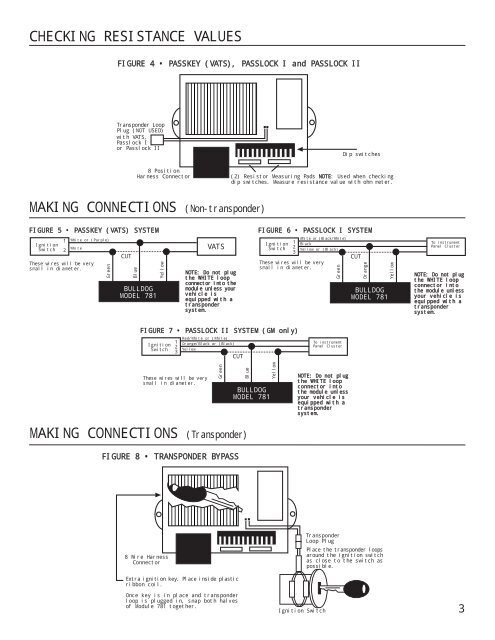
CHECKING RESISTANCE VALUESFIGURE 4 • PASSKEY (VATS), PASSLOCK I and PASSLOCK IITransponder LoopPlug (NOT USED)with VATS,Passlock Ior Passlock IIDip switches8 PositionHarness Connector(2) Resistor Measuring Pads NOTE: Used when checkingdip switches. Measure resistance value with ohm meter.MAKING CONNECTIONS (Non-transponder)FIGURE 5 • PASSKEY (VATS) SYSTEMIgnitionSwitch12White or (Purple)WhiteThese wires will be verysmall in diameter.GreenCUTBlueBULLDOGMODEL <strong>781</strong>YellowVATSNOTE: Do not plugthe WHITE loopconnector into themodule unless yourvehicle isequipped with atranspondersystem.FIGURE 6 • PASSLOCK I SYSTEMIgnitionSwitch123White or (Black/White)BlackYellow or (Black)These wires will be verysmall in diameter.GreenCUTOrangeBULLDOGMODEL <strong>781</strong>YellowTo instrumentPanel ClusterNOTE: Do not plugthe WHITE loopconnector intothe module unlessyour vehicle isequipped with atranspondersystem.FIGURE 7 • PASSLOCK II SYSTEM (GM only)IgnitionSwitch123Red/White or (White)Orange/Black or (Black)YellowCUTTo instrumentPanel ClusterThese wires will be verysmall in diameter.GreenBlueBULLDOGMODEL <strong>781</strong>YellowNOTE: Do not plugthe WHITE loopconnector intothe module unlessyour vehicle isequipped with atranspondersystem.MAKING CONNECTIONS (Transponder)FIGURE 8 • TRANSPONDER BYPASS8 Wire HarnessConnectorTransponderLoop PlugPlace the transponder loopsaround the ignition switchas close to the switch aspossible.Extra ignition key. Place inside plasticribbon coil.Once key is in place and transponderloop is plugged in, snap both halvesof Module <strong>781</strong> together.Ignition Switch3