8 MB - POWERLAB
8 MB - POWERLAB
8 MB - POWERLAB

You also want an ePaper? Increase the reach of your titles
YUMPU automatically turns print PDFs into web optimized ePapers that Google loves.
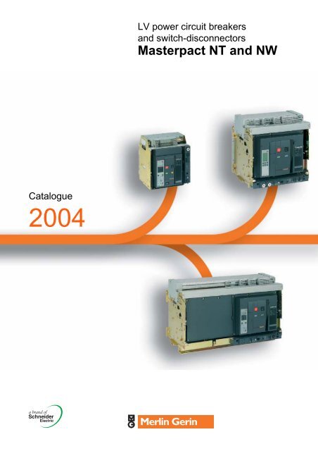
LV power circuit breakersand switch-disconnectorsMasterpact NT and NWCatalogue2004
0The Guiding System, the new way to create yourelectrical installationsA comprehensive offer of products with consistent designThe Guiding System is first and foremost a Merlin Gerin productoffer covering all electrical distribution needs. However, whatmakes all the difference is that these products have been designedto operate togheter: mechanical and electrical compatibility,interoperability, modularity, communication.Thus the electrical installation is both optimised and more efficient:better continuity of supply, enhanced safety for people andequipment, guaranteed upgradeability, effective monitoring andcontrol.Tools to simplify design and implementationWith the Guiding System, you have a comprehensive range of tools- the Guiding Tools - that will help you increase your productknowledge and product utilisation. Of course this is in compliancewith current standards and procedures.These tools include technical booklets and guides, design aidsoftware, training courses, etc. and are regularly updated.For a genuine partnership with youBecause each electrical installation is unique, there is no standardsolution. With the Guiding System, the variety of combinationsallows for genuine customisation solutions. You can create andimplement electrical installations to meet your creativerequirements and design knowledge.You and Merlin Gerin’s Guiding System form a genuine partnership.For more details on the Guiding System,consult www.merlin-gerin.com
A consistent design of offers fromMedium Voltage to Ultra terminalAll Merlin Gerin offers are designed according toelectrical, mechanical and communication consistencyrules.The products express this consistency by their overalldesign and shared ergonomics.0Electrical consistency:Discrimination guaranteesco-ordination between theoperating characteristics ofserial-connected circuitbreakers.Should a faultoccurs downstream, only thecircuit-breaker placedimmediately upstream fromthe fault will trip.The temperature rise testsperformed in the laboratoryguarantee safety anddurability of installations.Each product complies with or enhances system performance at coordinationlevel: breaking capacity, Isc, temperature rise, etc. formore safety, continuity of supply (discrimination) or economicoptimisation (cascading).The leading edge technologies employed in Merlin Gerin’sGuiding System ensure high performance levels in discriminationand cascading of protection devices, electrodynamic withstand ofswitches and current distributors, heat loss of devices, distributionblocks and enclosures.Likewise, inter-product ElectroMagnetic Compatibilty (EMC) isguaranteed.Mechanical consistency:Each product adopts dimensional standards simplifying andoptimising its use within the system.It shares the same accessories and auxiliaries and complies withglobal ergonomic choices (utilisation mode, operating mode, settingand configuration devices, tools, etc.) making its installation andoperation within the system a simpler process.Prefabricated and testedsolutions, upstream anddownstream from the devicecomplying with theIEC 60439-1 switchboardstandard.Direct connection of theCanalis KT busbar trunkingon the Masterpact 3200 Acircuit-breaker.Communication consistency:Each product complies with global choices in terms ofcommunication protocols (Modbus, Ethernet, etc.) for simplifiedintegration in the management, supervision and monitoringsystems.Thanks to the use of standard Web technologies, you can offeryour customers intelligent Merlin Gerin switchboards allowingeasy access to information: follow-up of currents, voltages,powers, consumption history, etc.Guiding Toolsfor more efficient designand implementationof your installations.Guiding Tools allow optimised useof the Guiding System offers. They simplify life andincrease productivity.1
0SM6Medium voltage switchboardsystem from 1 to 36 kVSatiaUltra compact ML/LV substationfrom 250 to 630 kVAMasterpactProtection switchgearfrom 100 to 6300 ATrihalMV/LV dry cast resintransformerfrom 160 to 5000 kVAEvolisMV vacuumswitchgear andcomponentsfrom 1 to 24 kV.The Technical guideThese technical guides help you comply withinstallation standards and rules i.e.:The electrical installation guide, theprotection guide, the switchboardimplementation guide, the technical bookletsand the co-ordination tables all form genuinereference tools for the design of highperformanceelectrical installations.For example, the LV protection co-ordinationguide - discrimination and cascading -optimises choice of protection andconnection devices while also increasingmarkedly continuity of supply in theinstallations.CAD software and toolsThe CAD software and tools enhanceproductivity and safety.They help you create your installationsby simplifying product choice througheasy browsing in the Guiding Systemoffers.Last but not least, they optimiseuse of our products while also complyingwith standards and proper procedures.2
0CompactProtection switchgear systemfrom 100 to 630 AMulti 9Modular protection switchgearsystem up to 125 APrisma PlusFunctional system for electricaldistribution switchboardsup to 3200 APragmaEnclosures fordistributionswitchboardsup to 160 ACanalisPrefabricated BusbarTrunkingfrom 25 to 4000 APowerLogicPowermanagementTrainingTraining allows you to acquire the MerlinGerin expertise (installation design, workwith power on, etc.) for increased efficiencyand a guarantee of improved customerservice.The training catalogue includes beginner’scourses in electrical distribution, knowledgeof MV and LV switchgear, operation andmaintenance of installations, design of LVinstallations to give but a few examples.3
PB100744-75The original Masterpact has set a new standard for powercircuit breakers around the world.Over the years, other major manufacturers have tried to keep upby developing products incorporating Masterpact’s most innovativefeatures, including the breaking principle, modular designand the use of composite materials.Today, Schneider Electric continues to innovatewith the new Merlin Gerin Masterpact NT and NW ranges.In addition to the traditional features of power circuit breakers(withdrawability, discrimination and low maintenance), Masterpactnow offers built-in communications and metering functions,all in optimised frame sizes.Masterpact NT and NW incorporate the latest technology toenhance both performance and safety. Easy to install, withuser-friendly, intuitive operation and environment-friendly design,they are, quite simply, circuit breakers of their time.4
MasterpactGeneral content 0Presentation 6Functions and characteristics 13Dimensions and connection 59Electrical diagrams 87Installation recommendations 97Additional characteristics 121Catalogue numbers, spare partsand order form 1275
PresentationNew Masterpact,new levels of performancePB100723-27Five performance levelsN1 - for standard applications with low short-circuit levels.H1 - for industrial sites with high short-circuit levels or installations with twoparallel-connected transformers.H2 - high-performance for heavy industry where very high short-circuits canoccur.H3 - for incoming devices supplying critical applications requiring both highperformance and a high level of discrimination.L1 - for high current-limiting capability and adiscrimination level (37 kA) as yet unequalled byany other circuit breaker of its type; intended forthe protection of cable-type feeders or to raisethe performance level of a switchboard whenthe transformer power rating is increased.PB100722-24PB100735-68Integration in a communications networkMasterpact can be integrated in a general supervision system to optimiseinstallation operation and maintenance. The communication architecture isopen, and may be upgraded for interfacing with any protocol.Switch-disconnector versionsThe switch-disconnectors are derived directly from the circuit breakersand offer the same features and performance levels. They are available inHA, NA and HF versions, depending on the models. The HF versionincludes instantaneous protection to prevent closing on a short-circuit.Once closed, the switch-disconnectors are unprotected and behave likeordinary switches. They are often used for busbar coupling.Special applicationsb 1000 V AC:v Masterpact NW H10 circuit breakers and switch-disconnectors, 800 to4000 A, 3P or 4P, drawout version and H10 circuit breaker performancelevelb DC:v Masterpact NW DC circuit breakers and switch-disconnectors, 1000 to4000 A, fixed and drawout versions and N and H circuit breakerperformance levels (see special DC catalogue no. ART10886)b right-hand neutral:v Masterpact NT630 to 1600 A and NW800 to 6300 A circuit breakers andswitch-disconnectors, 4P, fixed and drawout versions and H1 and H2 circuitbreaker performance levelsb industrial environments with high concentrations of sulphur compounds(standard IEC 721-3-3):v Masterpact NW800 to 4000 A circuit breakers with corrosion protection,drawout version and H2 circuit breaker performance levelb installation earthing:v Masterpact NW earthing switch, compatible with NW800 to 4000 A, 3Por 4P, drawout version with N1, H1, NA and HA performance levels.6
3 frame sizes, 2 familiesMasterpact NT800 to 1600 AThe new range of power circuit breakers includestwo families:b Masterpact NT, the world’s smallest true powercircuit breaker, with ratings from 800 to 1600 Ab Masterpact NW, in two frame sizes, one from800 to 4000 A and the other from 4000 A to6300 A.PB100726-21PB100831-76Masterpact NW800 to 4000 APB100724-33PB100747-764000 to 6300 APB100725-57PB100748-767
OptimisedvolumesPB100742-39The smallest circuit breaker inthe worldMasterpact NT innovates by offering all theperformance of a power circuit breaker in anextremely small volume. The 70 mm pole pitchmeans a three-pole drawout circuit breaker canbe installed in a switchboard section 400 mmwide and 400 mm deep.PB100743-53Practical installation solutionsThe new range improves upon all the installationsolutions which have already made Masterpacta success. It has been designed to standardiseswitchboards, optimise volumes and simplifyinstallation:b incoming connection to top or bottom terminalsb no safety clearance requiredb connection:v horizontal or vertical rear connectionv front connection with minimum extra spacev mixed front and rear connectionsb 115 mm pole pitch on all versionsb no derating up to 55 °C and 4000 A.PB100745-71Optimised volumesUp to 4000 A, Masterpact NW circuit breakersare all the same size, the same as the old M08to 32 range.From 4000 A to 6300 A, there is just one size,much smaller than before.Retrofit solutionsSpecial connections are available to replace afixed or drawout Masterpact M08 to 32 with aMasterpact NW, without modifying the busbarsor the door cut-out.8
Ease ofinstallationPB100737-64With optimised sizes, the Masterpact NT and NWranges simplify the design of switchboards andstandardise the installation of devices:b a single connection layout for Masterpact NTb three connection layouts for Masterpact NW:v one from 800 to 3200 Av one for 4000 Av one up to 6300 Ab identical connection terminals from 800 to6300 A (Masterpact NW)b front connection requires little space becausethe connectors to not increase the depth of thedevicerear connection to vertical or horizontal busbarssimply by turning the connectors 90°.Vertical front connection of a fixed Masterpact NW.PB100736-64PB100738-81Vertical and horizontal rear connectionof a fixed Masterpact NW.Connection to busbars.9
InnovationPB100740Greater dependability…Filtered breakingThe patented new design of the arc chutes includes stainless-steel filters.The chutes absorb the energy released during breaking, thus limiting thestresses exerted on the installation. They filter and cool the gasesproduced, reducing effects perceptible from the outside.Automatic unlatchingThe automatic unlatching of the circuit breaker operating mechanism forhigh short-circuits extends performance up to 150 kA. It produces ultra-fasttripping for all short-circuits higher than 37 kA (L1) and 65 kA (H3). Forlower short-circuits, the system does not react so that the control unit canprovide total discrimination with downstream devices.Filtered breaking.More intelligent trip units…Today, with the high speed of calculation, the small size of memories andadvances in miniaturisation, trip units have become circuit breaker controlunits offering increasingly powerful functions. They accurately measuresystem parameters, instantly calculate values, store data, log events, signalalarms, communicate, take action, etc. The new Masterpact ranges,equipped with Micrologic control units, constitute both an extremely reliableprotective device and an accurate measurement instrument.PB100739User friendly…Intuitive use…Micrologic control units are equipped with a digital LCD display used inconjunction with simple navigation buttons. Users can directly accessparameters and settings. Navigation between screens is intuitive and theimmediate display of values greatly simplifies settings. Text is displayed inthe desired language.Navigation buttons on a Micrologic P control unit.… backed by incomparable securityProtection functions are separate from the measurement functions and aremanaged by an ASIC electronic component. This independenceguarantees immunity from conducted or radiated disturbances and ensuresa high degree of reliability.A patented "double setting" system for protection functions establishes:b a maximum threshold set using the control-unit dialsb fine adjustments via the keypad or remotely. The fine adjustments forthresholds (to within one ampere) and tripping delays (to within a fraction ofa second) are displayed directly on the screen.The control unit cover can be lead-sealed to prevent uncontrolled access tothe dials and protect the settings.10
Ready forthe futureCompliance with environmentalrequirementsSchneider Electric fully takes into accountenvironmental requirements, starting right from thedesign phase of every product through to the end ofits service life:b the materials used for Masterpact are notpotentially dangerous to the environmentb the production facilities are non-polluting incompliance with the ISO 14001 standardb filtered breaking eliminates pollution in theswitchboardb the energy dissipated per pole is low, makingenergy losses insignificantb the materials are marked to facilitate sorting forrecycling at the end of product service life.Simple upgrading ofinstallationsInstallations change, power levels increase, newequipment is required and switchboards must beextended. Masterpact is designed to adapt to thesechanges:b all control units are interchangeableb communication with a supervision system is anoption that may be added at any timeb a reserve chassis can be pre-addressed so thatsystem parameters do not have to be modified whena drawout device is installed at a later dateb any future changes to the products will bedesigned to ensure continuity with the currentranges, thus simplifying installation upgrades.11
MasterpactFunctions and characteristicsPresentation 6General overview 14Detailed contents 14Circuit breakers and switch-disconnectors 16NT06 to NT16 and NW08 to NW63 16NT06 to NT16 18NW08 to NW63 20Micrologic control units 22Overview of functions 22Micrologic A "ammeter" 24Micrologic P "power" 26Micrologic H "harmonics" 30Accessories and test equipment 32Communication 34COM option in Masterpact 34Overview of functions 35Masterpact in a communication network 36Masterpact and the MPS100 Micro Power Server 38Connections 40Overview of solutions 40Optional accessories 41Locking 44On the device 44On the chassis 45Indication contacts 46Remote ON / OFF 48Remote tripping 51Accessories 52Source-changeover systems 53Presentation 53Mechanical interlocking 54Electrical interlocking 55Associated automatic controllers 56Display modules 57Dimensions and connection 59Electrical diagrams 87Installation recommendations 97Additional characteristics 121Catalogue numbers, spare parts and order form 12713
Functionsand characteristicsGeneral overview 0Detailed contentsPB100763-56PB100762-60This chapter describes all the functionsoffered by Masterpact NT and NW devices.The two product families have identicalfunctions implemented using the same ordifferent components depending on thecase.Circuit breakers and switch-disconnectors page 16b ratings:v Masterpact NT 630 to 1600 Av Masterpact NW 800 to 6300 Ab circuit breakers type N1, H1, H2, H3, L1b switch-disconnectors type NA, HA, HFb 3 or 4 polesb fixed or drawout versionsb option with neutral on the rightb protection derating.Micrologic control units page 22Ammeter A2.0 basic protection5.0 selective protection6.0 selective + earth-fault protection7.0 selective + earth-leakage protectionPower meter P5.0 selective protection6.0 selective + earth-fault protection7.0 selective + earth-leakage protectionHarmonic meter H5.0 selective protection6.0 selective + earth-fault protection7.0 selective + earth-leakage protectionb external sensor for earth-fault protectionb rectangular sensor for earth-leakage protectionb setting options (long-time rating plug):v low setting 0.4 to 0.8 x Irv high setting 0.8 to 1 x Irv without long-time protectionb external power-supply moduleb battery module.Communication page 34b COM option in Masterpactb Masterpact in a communication networkb Masterpact and the Micro Power Server MPS100.Connections page 40b rear connection (horizontal or vertical)b front connectionb mixed connectionsb optional accessoriesv bare-cable connectors and connector shieldsv terminal shieldsv vertical-connection adaptersv cable-lug adaptersv interphase barriersv spreadersv disconnectable front-connection adapterv safety shutters, shutter locking blocks, shutterposition indication and locking.DB101123DB101156DB101147DB101124DB101150DB10114914
Functionsand characteristicsGeneral overview 0Detailed contentsPB100764-56Locking page 44b pushbutton locking by padlockable transparent coverb OFF-position locking by padlock or keylockb chassis locking in disconnected position by keylockb chassis locking in connected, disconnectedand test positionsb door interlock (inhibits door opening with breakerin connected position)b racking interlock (inhibits racking with door open)b racking interlock between crank and OFF pushbuttonb automatic spring discharge before breaker removalb mismatch protection.DB101110 DB101109DB100766-56DB100765-56Indication contacts page 46b standard or low-level contacts:v ON/OFF indication (OF)v "fault trip" indication (SDE)v carriage switches for connected(CE) disconnected (CD) and test(CT) positionsb programmable contacts:v 2 contacts (M2C)v 6 contacts (M6C).DB101111M2C contact.DB101112OF contact.Remote operation page 48b remote ON/OFF:v gear motorv XF closing or MX opening voltage releasesv PF ready-to-close contactv options: RAR automatic or Res electrical remotereset- BPFE electrical closing pushbuttonb remote tripping function:v MN voltage release- standard- adjustable or non-adjustable delayv or second MX voltage release.DB101114 DB101113Gear motor.MX, XF and MN volagereleases.Accessories page 52b auxiliary terminal shieldb operation counterb escutcheonb transparent cover for escutcheonb escutcheon blanking plate.DB10111515
Functionsand characteristicsCircuit breakersand switch-disconnectors 0NT06 to NT16 and NW08 to NW63NT and NW selection criteriaMasterpact NTMasterpact NWStandard applicationsSpecial Standard applicationsapplicationsNT630-1600 H1 NT630-1600 H2 NT630-1000 L1 NT630-1600 H10 NW800-1600 N1 NW800-4000 H1Type of applicationStandardapplications withlow short-circuitcurrentsApplications withmedium-levelshort-circuitcurrentsLimiting circuitbreaker forprotection ofcable-type feedersor upgradedtransformerratings1000 V systems,e.g. mines andwind powerStandardapplications withlow short-circuitcurrentsIcu/Ics at 440 V 42 kA 50 kA 130 kA - 42 kA 65 kAIcu/Ics at 1000 V - - - 20 kA - -Icu/Ics at 500 V DC L/R < 15 ms - - - - - -Circuit breaker forindustrial sites withhigh short-circuitcurrentsPosition of neutral Left Left Left Left Left Left or rightFixed F F F F F FDrawout D D D D D DSwitch-disconnector version Yes No No Yes Yes YesFront connection Yes Yes Yes Yes Yes Yes up to 3200 ARear connection Yes Yes Yes Yes Yes YesType of Micrologic control unit A, P, H A, P, H A, P, H A, consult usfor P and HA, P, H A, P, HMasterpact NT06 to NT16 installation characteristicsCircuit breaker NT06, NT08, NT10 NT12, NT16Type H1 H2 L1 H10 H1 H2 H10ConnectionDrawout FC b b b b b b bRC b b b b b b bFixed FC b b b b b b bRC b b b b b b bDimensions (mm) H x W x DDrawout 3P 322 x 288 x 2774P 322 x 358 x 277Fixed 3P 301 x 276 x 1964P 301 x 346 x 196Weight (kg) (approximate)Drawout 3P/4P 30/39Fixed 3P/4P 14/18Masterpact NW08 to NW63 installation characteristicsCircuit breaker NW08, NW10, NW12, NW16 NW20Type N1 H1 H2 L1 H10 H1 H2 H3 L1 H10ConnectionDrawout FC b b b b - b b b b -RC b b b b b b b b b bFixed FC b b b - - b b - - -RC b b b - - b b - - -Dimensions (mm) H x W x DDrawout 3P 439 x 441 x 3954P 439 x 556 x 395Fixed 3P 352 x 442 x 2974P 352 x 537 x 297Weight (kg) (approximate)Drawout 3P/4P 90/120Fixed 3P/4P 60/80(1) Except 4000 A.16
Functionsand characteristicsCircuit breakersand switch-disconnectors 0NT06 to NT16 and NW08 to NW63Special applicationsNW800-4000 H2 NW2000-4000 H3 NW800-2000 L1 NW H10 NW H2 with anticorrosionprotectionHigh-performancecircuit breaker forheavy industrywith high shortcircuitcurrentsIncoming devicewith very highperformance forcriticalapplicationsLimiting circuitbreaker forprotection ofcable-type feedersor upgradedtransformerratings1000 V systems,e.g. mines andwind powerEnvironments withhigh sulphurcontentsNW1000-4000DC NNW1000-4000DC HNW earthingswitchDC system DC system Installationearthing100 kA 150 kA 150 kA - 100 kA - - -- - - 50 kA - - - -- - - - - 35 kA 85 kA -Left or right Left Left Left Left or right - - -F - - - - F F -D D D D D D D DYes Yes Yes Yes Yes Yes Yes YesYes up to 3200 A Yes up to 3200 A Yes up to 3200 A No Yes up to 3200 A No No Yes up to 3200 AYes Yes Yes Yes Yes Yes Yes YesA, P, H A, P, H A, P, H A, consult usfor P and HA, P, H DC Micrologic DC Micrologic -NW25, NW32, NW40NW40b, NW50, NW63H1 H2 H3 H10 H1 H2b (1) b (1) b (1) - - -b b b b b bb (1) b (1) - - - -b b - - b b479 x 786 x 395479 x 1016 x 395352 x 767 x 297352 x 997 x 297225/300120/16017
Functionsand characteristicsCircuit breakersand switch-disconnectors 0NT06 to NT16PB100767-48Common characteristicsNumber of poles 3/4Rated insulation voltage (V) Ui 1000Impulse withstand voltage (kV) Uimp 12Rated operational voltage (V AC 50/60 Hz) Ue 690/1000Suitability for isolation IEC 60947-2Degree of pollution IEC 60664-1 3Circuit-breaker characteristics as per IEC 60947-2Rated current (A) In at 40 °C/50 °C (1)Rating of 4th pole (A)Sensor ratings (A)Type of circuit breakerUltimate breaking capacity (kA rms) Icu 220/415 VV AC 50/60 Hz440 V525 V690 V1000 VRated service breaking capacity (kA rms) Ics % IcuUtilisation categoryRated short-time withstand current (kA rms)V AC 50/60 HzIcw0.5 s1 s3 sIntegrated instantaneous protection (kA peak ±10 %)Rated making capacity (kA peak) Icm 220/415 VV AC 50/60 Hz440 V525 V690 V1000 VBreak time (ms) between tripping order and arc extinctionClosing time (ms)Circuit-breaker characteristics as per NEMA AB1Breaking capacity (kA)V AC 50/60 Hz240 V480 V600 V(1) 50 °C: rear vertical connected. Refer to temperaturederating tables for other connection types.(2) See the current-limiting curves in the "additionalcharacteristics" section.(3) SELLIM system.(4) Available for 480 V NEMA.(5) Suitable for motor control (direct-on-line starting).Switch-disconnector characteristics as per IEC 60947-3 and Annex AType of switch-disconnectorRated making capacity (kA peak) Icm 220 VAC23A/AC3 category V AC 50/60 Hz440 V525/690 V1000 VRated short-time withstand current (kA rms) Icw 0.5 sAC23A/AC3 category V AC 50/60 Hz1 s3 sUltimate breaking capacity Icu (kA rms) with an external protection relay 690 VMaximum time delay: 350 msMechanical and electrical durability as per IEC 60947-2/3 at In/IeService life Mechanical with maintenanceC/O cycles x 1000without maintenanceType of circuit breakerIn (A)Rated currentC/O cycles x 1000 Electrical without maintenance 440 V (4)IEC 60947-2690 V1000 VType of circuit breaker or switch-disconnector Ie (A)Rated operationnal currentAC23AC/O cycles x 1000 Electrical without maintenance 440 V (4)IEC 60947-3690VType of circuit breaker or switch-disconnector Ie (A)Rated operationnal current AC3 (5)Motor power380/415 V (kW)440 V (kW)C/O cycles x 1000 Electrical without maintenance 440 V (4)IEC 60947-3 Annex M/IEC 60947-4-1690 V18
Functionsand characteristicsCircuit breakersand switch-disconnectors 0NT06 to NT16Sensor selectionSensor rating (A) 250 (1) 400 630 800 1000 1250 1600Ir thresold setting(A) 100 to 250 160 to 400 250 to 630 320 to 800 400 to 1000 500 to 1250 640 to 1600(1) For NT02 rating, please consult us.NT06 NT08 NT10 NT12 NT16630 800 1000 1250 1600630 800 1000 1250 1600400 to 630 400 to 800 400 to 1000 630 to 1250 800 to 1600H1 H2 L1 (2) H10 H1 H2 H1042 50 150 - 42 50 -42 50 130 - 42 50 -42 42 100 - 42 42 -42 42 25 - 42 42 -- - - 20 - - 20100 % 100 %B B A B B B B42 36 10 20 42 36 2042 36 - 20 - 36 2024 20 - - 24 20 -- 90 10 x In (3) - - 90 -88 105 330 - 88 105 -88 105 286 - 88 105 -88 88 220 - 88 88 -88 88 52 - 88 88 -- - - 42 - - 4225 25 9 - 25 25 -< 50 < 5042 50 150 - 42 50 -42 50 100 - 42 50 -42 42 25 - 42 42 -HA HA10 HA HA1075 - 75 -75 - 75 -75 - 75 -- 42 - 4236 20 36 2036 20 36 2020 20 20 2036 362512.5H1 H2 L1 H10 H1 H2 L1 H10 H1 H2 L1 H10 H1 H2 H10 H10 H1 H2630 800 1000 1250 16006 6 3 - 6 6 3 - 6 6 3 - 6 6 - - 6 63 3 2 - 3 3 2 - 3 3 2 - 3 3 - - 3 3- - - 0.5 - - - 0.5 - - - 0.5 - - 0.5 0.5 - -H1/H2/HA630 800 1000 1250 16006 6 6 6 63 3 3 3 3H1/H2/HA500 630 800 1000 1000y 250 250 to 335 335 to 450 450 to 560 450 to 560y 300 300 to 400 400 to 500 500 to 630 500 to 6306-19
Functionsand characteristicsCircuit breakersand switch-disconnectors 0NW08 to NW63PB100768-38Common characteristicsNumber of poles 3/4Rated insulation voltage (V) Ui 1000/1250Impulse withstand voltage (kV) Uimp 12Rated operational voltage (V AC 50/60 Hz) Ue 690/1150Suitability for isolation IEC 60947-2Degree of pollution IEC 60664-1 4 (1000 V) / 3 (1250 V)Circuit-breaker characteristics as per IEC 60947-2Rated current (A) at 40 °C / 50 °C (1)Rating of 4th pole (A)Sensor ratings (A)PB100769-70Type of circuit breakerUltimate breaking capacity (kA rms)V AC 50/60 HzRated service breaking capacity (kA rms) Ics % IcuUtilisation categoryRated short-time withstand current (kA rms)V AC 50/60 HzIcw1 s3 sIntegrated instantaneous protection (kA peak ±10 %)Rated making capacity (kA peak)V AC 50/60 HzBreak time (ms) between tripping order and arc extinctionClosing time (ms)IcuIcmCircuit-breaker characteristics as per NEMA AB1Breaking capacity (kA)V AC 50/60 Hz220/415/440 V525 V690 V1150 V220/415/440 V525 V690 V1150 V240/480 V600 VUnprotected circuit-breaker characteristics:Tripping by shunt trip as per IEC 60947-2Type of circuit breakerUltimate breaking capacity (kA rms) V AC 50/60 Hz Icu 220...690 VRated service breaking capacity (kA rms) Ics % IcuRated short-time withstand current (kA rms) Icw 1 s3 sOverload and short-circuit protection with external protection relay:short-circuit protection, maximum delay: 350 ms (4)Rated making capacity (kA peak) V AC 50/60 Hz Icm 220...690 V(1) 50 °C: rear vertical connected. Refer to temperaturederating tables for other connection types.(2) See the current-limiting curves in the "additionalcharacteristics" section.(3) Equipped with a trip unit with a making currentof 90 kA peak.(4) External protection must comply with permissible thermalconstraints of the circuit breaker (please consult us).No fault-trip indication by the SDE or the reset button.(5) Available for 480 V NEMA.(6) Suitable for motor control (direct-on-line starting).Switch-disconnector characteristics as per IEC 60947-3and Annex AType of switch-disconnectorRated making capacity (kA peak)AC23A/AC3 category V AC 50/60 HzRated short-time withstand current (kA rms)AC23A/AC3 category V AC 50/60 HzIcmIcw220...690 V1150 V0.5 s1 s3 sMechanical and electrical durability as per IEC 60947-2/3 at In/IeService life Mechanical with maintenanceC/O cycles x 1000without maintenanceType of circuit breakerIn (A)Rated currentC/O cycles x 1000 Electrical without maintenance 440 V (5)IEC 60947-2690 V1150 VType of circuit breaker or switch-disconnector Ie (A)Rated operational currentAC23AC/O cycles x 1000 Electrical without maintenance 440 V (5)IEC 60947-3690 VType of circuit breaker or switch-disconnector Ie (A)Rated operational current AC3 (6)Motor power380/415 V (kW)440 V (5) (kW)690 V (kW)C/O cycles x 1000 Electrical without maintenance 440/690 V (5)IEC 60947-3 Annex M/IEC 60947-4-120
Functionsand characteristicsCircuit breakersand switch-disconnectors 0NW08 to NW63Sensor selectionSensor rating (A) 250 (1) 400 630 800 1000 1250 1600 2000 2500 3200 4000 5000 6300Ir thresold setting(A) 100 160 250 320 400 500 630 800 1000 1250 1600 2000 2500to 250 to 400 to 630 to 800 to 1000 to 1250 to 1600 to 2000 to 2500 to 3200 to 4000 to 5000 to 6300(1) For NW02 rating, please consult us.NW08 NW10 NW12 NW16 NW20 NW25 NW32 NW40 NW40b NW50 NW63800 1000 1250 1600 2000 2500 3200 4000 4000 5000 6300800 1000 1250 1600 2000 2500 3200 4000 4000 5000 6300400to 800400to 1000630to 1250800 to 1600 1000 to 2000 1250to 25001600to 32002000 to 4000 2000to 40002500to 50003200to 6300N1 H1 H2 L1 (2) H10 H1 H2 H3 L1 (2) H10 H1 H2 H3 H10 H1 H242 65 100 150 - 65 100 150 150 - 65 100 150 - 100 15042 65 85 130 - 65 85 130 130 - 65 85 130 - 100 13042 65 85 100 - 65 85 100 100 - 65 85 100 - 100 100- - - - 50 - - - - 50 - - - 50 - -100 % 100 % 100 % 100 %B B B B42 65 85 30 50 65 85 65 30 50 65 85 65 50 100 10022 36 50 30 50 36 75 65 30 50 65 75 65 50 100 100Without Without 190 80 Without Without 190 150 80 Without Without 190 150 Without Without 27088 143 220 330 - 143 220 330 330 - 143 220 330 - 220 33088 143 187 286 - 143 187 286 286 - 143 187 286 - 220 28688 143 187 220 - 143 187 220 220 - 143 187 220 - 220 220- - - - 105 - - - - 105 - - - 105 - -25 25 25 10 25 25 25 25 10 25 25 25 25 25 25 25< 70 < 70 < 70 < 8042 65 100 150 - 65 100 150 150 - 65 100 150 - 100 15042 65 85 100 - 65 85 100 100 - 65 85 100 - 100 100HA HF (3) HA HF (3) HA HF (3) HA50 85 50 85 55 85 85100 % 100 % 100 % 100 %50 85 50 85 55 85 8536 50 36 75 55 75 85Without Without Without Without Without Without Without105 187 105 187 121 187 187NW08/NW10/NW12 NW16 NW20 NW25/NW32/NW40 NW40b/NW50/NW63NA HA HF HA10 HA HF HA10 HA HF HA10 HA HF HA10 HA88 105 187 - 105 187 - 105 187 - 121 187 - 187- - - 105 - - 105 - - 105 - - 105 -- - - - - - - - - - - - - -42 50 85 50 50 85 50 50 85 50 55 85 50 85- 36 50 50 50 50 50 50 50 50 55 75 50 8525 20 1012.5 10 5N1/H1/H2 L1 H10 H1/H2 L1 H10 H1/H2 H3 H10 H1 H2800/1000/1250/1600 2000 2500/3200/4000 4000b/5000/630010 3 - 8 3 - 5 1.25 - 1.5 1.510 3 - 6 3 - 2.5 1.25 - 1.5 1.5- - 0.5 - - 0.5 - - 0.5 - -H1/H2/NA/HA/HF H1/H2/H3/HA/HF H1/H2/HA800/1000/1250/1600 2000 2500/3200/4000 4000b/5000/630010 8 5 1.510 6 2.5 1.5H1/H2/HA/HFH1/H2/H3/HA/HF800 1000 1250 1600 2000335 to 450 450 to 560 560 to 670 670 to 900 900 to 1150400 to 500 500 to 630 500 to 800 800 to 1000 1000 to 1300y 800 800 to 1000 1000 to 1250 1250 to 1600 1600 to 2000621
Functionsand characteristicsMicrologic control units 0Overview of functionsAll Masterpact circuit breakers are equippedwith a Micrologic control unit that can bechanged on site.Control units are designed to protect Powercircuits and loads. Alarms may beprogrammed for remote indications.Measurements of current, voltage,frequency, power and power qualityoptimise continuity of service and energymanagement.DependabilityIntegration of protection functions in an ASIC electronic component used in allMicrologic control units guarantees a high degree of reliability and immunity toconducted or radiated disturbances.On Micrologic A, P and H control units, advanced functions are managed by anindependent microprocessor.Micrologic name codesCurrent protection2.0 AX Y ZX: type of protectionb 2 for basic protectionb 5 for selective protectionb 6 for selective + earth-fault protectionb 7 for selective + earth-leakage protection.DB101116Micrologic 2: basic protectionProtection:long time+ instantaneousY: control-unit generationIdentification of the control-unit generation."0" signifies the first generation.Micrologic 5: basic protectionZ: type of measurementb A for "ammeter"b P for "power meter"b H for "harmonic meter".DB101117Protection:long time+ short time+ instantaneousPB100772-32DB101117Micrologic 6: selective + earth-fault protectionDB101118Protection:long time+ short time+ instantaneous+ earth faultMicrologic 7: selective + earth-leakage protectionDB101117DB101119Protection:long time+ short time+ instantaneous+ earth leakage22
Functionsand characteristicsMicrologic control units 0Overview of functionsMeasurements and programmable protectionA: ammeterb I 1, I 2, I 3, I N, I earth-fault, I earth-leakage and maximeter for these measurementsb fault indicationsb settings in amperes and in seconds.P: A + power meter + programmable protectionb measurements of V, A, W, VAR, VA, Wh, VARh, VAh, Hz, V peak, A peak, power factor and maximeters and minimetersb IDMTL long-time protection, minimum and maximum voltage and frequency, voltage and current imbalance,phase sequence, reverse powerb load shedding and reconnection depending on power or currentb measurements of interrupted currents, differentiated fault indications, maintenance indications, event historiesand time-stamping, etc.H: P + harmonicsb power quality: fundamentals, distortion, amplitude and phase of harmonics up to the31st orderb waveform capture after fault, alarm or on requestb enhanced alarm programming: thresholds and actions.2.0 ADB1011205.0 A5.0 P5.0 HDB101121DB101122DB1011226.0 A6.0 P6.0 HDB101123DB101124DB1011247.0 A7.0 P7.0 HDB101123DB101124DB10112423
Functionsand characteristicsMicrologic control units 0Micrologic A "ammeter"DB101125Micrologic A control units protect powercircuits.They also offer measurements, display,communication and current maximeters.Version 6 provides earth-fault protection,version 7 provides earth-leakage protection.Protection settings ..................................................................Protection thresholds and delays are set using the adjustment dials.The selected values are momentarily displayed in amperes and in seconds.Overload protectionTrue rms long-time protection.Thermal memory: thermal image before and after tripping.Setting accuracy may be enhanced by limiting the setting range using a differentlong-time rating plug.The long-time rating plug "OFF" enables to cancel the overload protection.Short-circuit protectionShort-time (rms) and instantaneous protection.Selection of I 2 t type (ON or OFF) for short-time delay.Earth fault protectionResidual or source ground return.Selection of I 2 t type (ON or OFF) for delay.Residual earth-leakage protection (Vigi).Operation without an external power supply.q Protected against nuisance tripping.k DC-component withstand class A up to 10 A.Neutral protectionOn three-pole circuit breakers, neutral protection is not possible.On four-pole circuit breakers, neutral protection may be set using a three-positionswitch: neutral unprotected (4P 3d), neutral protection at 0.5 In (4P 3d + N/2), neutralprotection at In (4P 4d).Zone selective interlocking (ZSI)A ZSI terminal block may be used to interconnect a number of control units to providetotal discrimination for short-time and earth-fault protection, without a delay beforetripping."Ammeter" measurements .....................................................Micrologic A control units measure the true rms value of currents.They provide continuous current measurements from 0.2 to 20 In and are accurateto within 1.5% (including the sensors).A digital LCD screen continuously displays the most heavily loaded phase (Imax) ordisplays the I 1, I 2, I 3, I N, I g, I ∆n, stored-current (maximeter) and setting values bysuccessively pressing the navigation button.The optional external power supply makes it possible to display currents < 20 % In.Below 0.05 In, measurements are not significant. Between 0.05 and 0.2 In, accuracyis to within 0.5% In + 1.5% of the reading.Communication optionIn conjunction with the COM communication option, the control unit transmits thefollowing:b setting valuesb all "ammeter" measurementsb tripping causesb maximeter reset.1 Long-time current setting and tripping delay.2 Overload signal (LED) at 1.125 Ir.3 Short-time pick-up and tripping delay.4 Instantaneous pick-up.5 Earth-leakage or earth-fault pick-up and tripping delay.6 Earth-leakage or earth-fault test button.7 Long-time rating plug screw.8 Test connector.9 Lamp test, reset and battery test.10 Indication of tripping cause.11 Digital display.12 Three-phase bargraph and ammeter.13 Navigation buttons.Note: Micrologic A control units come with a transparent leadsealcover as standard.24
Functionsand characteristicsMicrologic control units 0Micrologic A "ammeter"ProtectionMicrologic 2.0 ALong timeCurrent setting (A) Ir = In x … 0.4 0.5 0.6 0.7 0.8 0.9 0.95 0.98 1Tripping between 1.05 and 1.20 x IrOther ranges or disable by changing long-time rating plugTime setting tr (s) 0.5 1 2 4 8 12 16 20 24Time delay (s) Accuracy: 0 to -30 % 1.5 x Ir 12.5 25 50 100 200 300 400 500 600Accuracy: 0 to -20 % 6 x Ir 0.7 (1) 1 2 4 8 12 16 20 24Accuracy: 0 to -20 % 7.2 x Ir 0.7 (2) 0.69 1.38 2.7 5.5 8.3 11 13.8 16.6Thermal memory20 minutes before and after tripping(1) 0 to -40 % - (2) 0 to -60 %InstantaneousPick-up (A) Isd = Ir x … 1.5 2 2.5 3 4 5 6 8 10Accuracy: ±10 %Time delayMax resettable time: 20 msMax break time: 80 msDB101126AmmeterMicrologic 2.0 AContinuous current measurementsDisplay from 20 to 200 % of In I1 I2 I3 INAccuracy: 1.5 % (including sensors)No auxiliary source (where I > 20 % In)MaximetersI1 max I2 max I3 max IN maxProtectionMicrologic 5.0 / 6.0 / 7.0 ALong timeMicrologic 5.0 / 6.0 / 7.0 ACurrent setting (A) Ir = In x … 0.4 0.5 0.6 0.7 0.8 0.9 0.95 0.98 1Tripping between 1.05 and 1.20 x IrOther ranges or disable by changing long-time rating plugTime setting tr (s) 0.5 1 2 4 8 12 16 20 24Time delay (s) Accuracy: 0 to -30 % 1.5 x Ir 12.5 25 50 100 200 300 400 500 600Accuracy: 0 to -20 % 6 x Ir 0.7 (1) 1 2 4 8 12 16 20 24Accuracy: 0 to -20 % 7.2 x Ir 0.7 (2) 0.69 1.38 2.7 5.5 8.3 11 13.8 16.6Thermal memory20 minutes before and after tripping(1) 0 to -40 % - (2) 0 to -60 %Short timePick-up (A) Isd = Ir x … 1.5 2 2.5 3 4 5 6 8 10Accuracy: ±10 %Time setting tsd (s) Settings I 2 t Off 0 0.1 0.2 0.3 0.4I 2 t On - 0.1 0.2 0.3 0.4Time delay (ms) at 10 x Ir tsd (max resettable time) 20 80 140 230 350(I 2 t Off or I 2 t On) tsd (max break time) 80 140 200 320 500InstantaneousPick-up (A) Ii = In x … 2 3 4 6 8 10 12 15 offAccuracy: ±10 %Time delayMax resettable time: 20 msMax break time: 80 msEarth faultMicrologic 6.0 APick-up (A) Ig = In x … A B C D E F G H JAccuracy: ±10 % In y 400 A 0.3 0.3 0.4 0.5 0.6 0.7 0.8 0.9 1400 A < In < 1250 A 0.2 0.3 0.4 0.5 0.6 0.7 0.8 0.9 1In u 1250 A 500 640 720 800 880 960 1040 1120 1200Time setting tg (s) Settings I 2 t Off 0 0.1 0.2 0.3 0.4I 2 t On - 0.1 0.2 0.3 0.4Time delay (ms) tg (max resettable time) 20 80 140 230 350at In or 1200 A (I 2 t Off or I 2 t On) tg (max break time) 80 140 200 320 500Residual earth leakage (Vigi)Micrologic 7.0 ASensitivity (A) I∆n 0.5 1 2 3 5 7 10 20 30Accuracy: 0 to -20 %Time delay ∆t (ms) Settings 60 140 230 350 800∆t (max resettable time) 60 140 230 350 800∆t (max break time) 140 200 320 500 1000DB101127DB101128DB101129AmmeterMicrologic 5.0 / 6.0 / 7.0 AContinuous current measurementsDisplay from 20 to 200 % of In I1 I2 I3 IN Ig I∆nAccuracy: 1.5 % (including sensors)No auxiliary source (where I > 20 % In)MaximetersI1 max I2 max I3 max IN max Ig max I∆n maxNote: All current-based protection functions require no auxiliary source.The test / reset button resets maximeters, clears the tripping indication and tests the battery.25
Functionsand characteristicsMicrologic control units 0Micrologic P "power"DB101485Micrologic P control units include all thefunctions offered by Micrologic A.In addition, they measure voltages andcalculate power and energy values.They also offer new protection functionsbased on currents, voltages, frequency andpower reinforce load protection.1 Long-time current setting and tripping delay.2 Overload signal (LED).3 Short-time pick-up and tripping delay.4 Instantaneous pick-up.5 Earth-leakage or earth-fault pick-up and tripping delay.6 Earth-leakage or earth-fault test button.7 Long-time rating plug screw.8 Test connector.9 Lamp + battery test and indications reset.10 Indication of tripping cause.11 High-resolution screen.12 Measurement display.13 Maintenance indicators.14 Protection settings.15 Navigation buttons.16 Hole for settings lockout pin on cover.Protection settings ....................................................... +The adjustable protection functions are identical to those of Micrologic A (overloads,short-circuits, earth-fault and earth-leakage protection).Fine adjustmentWithin the range determined by the adjustment dial, fine adjustment of thresholds (towithin one ampere) and time delays (to within one second) is possible on the keypador remotely using the COM option.IDMTL (Inverse Definite Minimum Time lag) settingCoordination with fuse-type or medium-voltage protection systems is optimised byadjusting the slope of the overload-protection curve. This setting also ensures betteroperation of this protection function with certain loads.Neutral protectionOn three-pole circuit breakers, neutral protection may be set using the keypad orremotely using the COM option, to one of four positions: neutral unprotected (4P 3d),neutral protection at 0.5 In (4P 3d + N/2), neutral protection at In (4P 4d) and neutralprotection at 1,6 In (4P 3d + 1,6N). Neutral protection at 1,6 In is used when theneutral conductor is twice the size of the phase conductors (major load imbalance,high level of third order harmonics).On four-pole circuit breakers, neutral protection may be set using a three-positionswitch or the keypad: neutral unprotected (4P 3d), neutral protection at 0.5 In (4P 3d+ N/2), neutral protection at In (4P 4d). Neutral protection produces no effect if thelong-time curve is set to one of the IDMTL protection settings.Programmable alarms and other protection..................... ....Depending on the thresholds and time delays set using the keypad or remotely usingthe COM option, the Micrologic P control unit monitors currents and voltage, power,frequency and the phase sequence. Each threshold overrun is signalled remotely viathe COM option. Each threshold overrun may be combined with tripping (protection)or an indication carried out by an optional M2C or M6C programmable contact(alarm), or both (protection and alarm).Load shedding and reconnection..........................................Load shedding and reconnection parameters may be set according to the power orthe current flowing through the circuit breaker. Load shedding is carried out by asupervisor via the COM option or by an M2C or M6C programmable contact.Measurements..........................................................................The Micrologic P control unit calculates in real time all the electrical values (V, A, W,VAR, VA, Wh, VARh, VAh, Hz), power factors and crest factors.The Micrologic P control unit also calculates demand current and demand powerover an adjustable time period. Each measurement is associated with a minimeterand a maximeter.In the event of tripping on a fault, the interrupted current is stored. The optionalexternal power supply makes it possible to display the value with the circuit breakeropen or not supplied.Histories and maintenance indicators...................................The last ten trips and alarms are recorded in two separate history files. Maintenanceindications (contact wear, operation cycles, etc.) are recorded for local access.Indication option via programmable contactsThe M2C (two contacts) and M6C (six contacts) auxiliary contacts may be used tosignal threshold overruns or status changes. They can be programmed using thekeypad on the Micrologic P control unit or remotely using the COM option.Communication option (COM)The communication option may be used to:b remotely read and set parameters for the protection functionsb transmit all the calculated indicators and measurementsb signal the causes of tripping and alarmsb consult the history files and the maintenance-indicator register.b maximeter reset.An event log and a maintenance register, stored in control-unit memory but notavailable locally, may be accessed in addition via the COM option.Note: Micrologic P control units come with a non-transparentlead-seal cover as standard.26
Functionsand characteristicsMicrologic control units 0Micrologic P "power"Protection Micrologic 5.0 / 6.0 / 7.0 P +Long time (rms)Micrologic 5.0 / 6.0 / 7.0 PCurrent setting (A) Ir = In x … 0.4 0.5 0.6 0.7 0.8 0.9 0.95 0.98 1Tripping between 1.05 and 1.20 x IrOther ranges or disable by changing long-time rating plugTime setting tr (s) 0.5 1 2 4 8 12 16 20 24Time delay (s) Accuracy: 0 to -30 % 1.5 x Ir 12.5 25 50 100 200 300 400 500 600Accuracy: 0 to -20 % 6 x Ir 0.7 (1) 1 2 4 8 12 16 20 24Accuracy: 0 to -20 % 7.2 x Ir 0.7 (2) 0.69 1.38 2.7 5.5 8.3 11 13.8 16.6IDMTL setting Curve slope SIT VIT EIT HVFuse DTThermal memory20 minutes before and after tripping(1) 0 to -40 % - (2) 0 to -60 %Short time (rms)Pick-up (A) Isd = Ir x … 1.5 2 2.5 3 4 5 6 8 10Accuracy: ±10 %Time setting tsd (s) Settings I 2 t Off 0 0.1 0.2 0.3 0.4I 2 t On - 0.1 0.2 0.3 0.4Time delay (ms) at 10 Ir tsd (max resettable time) 20 80 140 230 350(I 2 t Off or I 2 t On) tsd (max break time) 80 140 200 320 500InstantaneousPick-up (A) Ii = In x … 2 3 4 6 8 10 12 15 offAccuracy: ±10 %Time delayEarth faultMax resettable time: 20 msMax break time: 80 msMicrologic 6.0 PPick-up (A) Ig = In x … A B C D E F G H JAccuracy: ±10 % In y 400 A 0.3 0.3 0.4 0.5 0.6 0.7 0.8 0.9 1400 A < In < 1250 A 0.2 0.3 0.4 0.5 0.6 0.7 0.8 0.9 1In u 1250 A 500 640 720 800 880 960 1040 1120 1200Time setting tg (s) Settings I 2 t Off 0 0.1 0.2 0.3 0.4I 2 t On - 0.1 0.2 0.3 0.4Time delay (ms) tg (max resettable time) 20 80 140 230 350at In or 1200 A (I 2 t Off or I 2 t On) tg (max break time) 80 140 200 320 500Residual earth leakage (Vigi)Micrologic 7.0 PSensitivity (A) I∆n 0.5 1 2 3 5 7 10 20 30Accuracy: 0 to -20 %Time delay ∆t (ms) Settings 60 140 230 350 800∆t (max resettable time) 60 140 230 350 800∆t (max break time) 140 200 320 500 1000DB101130DB101128DB101129Alarms and other protectionMicrologic 5.0 / 6.0 / 7.0 PCurrent Seuil TemporisationDéséquilibre de courant Iunbalance 0.05 to 0.6 Iaverage 1 to 40 sMax. de courant moyen Imax demand : I1, I2, I3, IN, 0.2 In to In 15 to 1500 sEarth fault alarmIt 20 A to 1200 A 1 to 10 sVoltageVoltage unbalance Uunbalance 2 to 30 % x Uaverage 1 to 40 sMinimum voltage Umin 100 to Umax between phases 1.2 to 5 sMaximum voltage Umax Umin to 1200 between phases 1.2 to 5 sPowerReverse power rP 5 to 500 kW 0.2 to 20 sFrequencyMinimum frequency Fmin 45 to Fmax 1.2 to 5 sMaximum frequency Fmax Fmin to 440 Hz 1.2 to 5 sPhase sequenceSequense (alarm) ∆Ø Ø1/2/3 or Ø1/3/2 0.3 sLoad shedding and reconnectionMicrologic 5.0 / 6.0 / 7.0 PMeasured value Seuil TemporisationCurrent I 0.5 to 1 Ir per phases 20 % tr to 80 % trPower P 200 kW to 10 MW 10 to 3600 sDB101142DB101143Note: all current-based protection functions require no auxiliary source.Voltage-based protection functions are connected to AC power via a voltage measurement input built into the circuit breaker.27
Functionsand characteristicsMicrologic control units 0Micrologic P "power"DB101133DB101134Navigation from one display to another is intuitive. The six buttons on the keypadprovide access to the menus and easy selection of values. When the setting cover isclosed, the keypad may no longer be used to access the protection settings, but stillprovides access to the displays for measurements, histories, indicators, etc.DB101135Default display.Display of a voltage.DB101136Display of a maximum current.Display of a power.Measurements..........................................................................Instantaneous valuesThe value displayed on the screen is refreshed every second.Minimum and maximum values of measurements are stored in memory (minimetersand maximeters).CurrentsI rms A 1 2 3 NA E-fault E-leakageI max rms A 1 2 3 NA E-fault E-leakageVoltagesU rms V 12 23 31V rms V 1N 2N 3NU average rms V (U12 + U23 + U31) / 3U unbalance %Power, energyP active, Q reactive, S apparent W, Var, VA TotalsE active, E reactive, E apparent Wh, VARh, VAh Totals consumed - suppliedTotals consumedTotals suppliedPower factor PF TotalFrequenciesFHzDB101137Display of a frequency.DB101138Display of a demand power.Demand meteringThe demand is calculated over a fixed or sliding time window that may beprogrammed from 5 to 60 minutes. According to the contract signed with the powersupplier, an indicator associated with a load shedding function makes it possible toavoid or minimise the costs of overrunning the subscribed power. Maximum demandvalues are systematically stored and time stamped (maximeter).CurrentsI demand A 1 2 3 NA E-fault E-leakageI max demand A 1 2 3 NA E-fault E-leakagePowerP, Q, S demand W, Var, VA TotalsP, Q, S max demand W, Var, VA TotalsMinimeters and maximetersOnly the current and power maximeters may be displayed on the screen.DB101139Display of a tripping history.DB101140Display after tripping.Histories ...................................................................................The last ten trips and alarms are recorded in two separate history files that may bedisplayed on the screen.b tripping history:v type of faultv date and timev values measured at the time of tripping (interrupted current, etc.)b alarm history:v type of alarmv date and timev values measured at the time of the alarm.Maintenance indicators (with COM option)...........................A number of maintenance indicators may be called up on the screen:b contact wearb operation counter:v cumulative totalv total since last reset.28
Functionsand characteristicsMicrologic control units 0Micrologic P "power"DB101523Display of an event log on a supervisor.With the communication optionAdditional measurements, maximeters and minimetersCertain measured or calculated values are only accessible with the COMcommunication option:b I peak / 2, (I1 + I2 + I3)/3, I unbalanceb load level in % Irb total power factor.The maximeters and minimeters are available only via the COM option for use witha supervisor.Event logAll events are time stamped.b tripsb beginning and end of alarmsb modifications to settings and parametersb counter resetsb system faults:b fallback positionb thermal self-protectionb loss of timeb overrun of wear indicatorsb test-kit connectionsb etc.Maintenance registerUsed as an aid in troubleshooting and to better plan for device maintenanceoperations.b highest current measuredb operation counterb number of test-kit connectionsb number of trips in operating mode and in test modeb contact-wear indicator.Additional technical characteristicsSetting the display languageSystem messages may be displayed in six different languages. The desiredlanguage is selected via the keypad.Protection functionsAll current-based protection functions require no auxiliary source. Voltage-basedprotection functions are connected to AC power via a voltage measurement inputbuilt into the circuit breaker.Measurement functionsMeasurement functions are independent of the protection functions.The high-accuracy measurement module operates independently of the protectionmodule, while remaining synchronised with protection events.Measurement-calculation modeb measurement functions implement the new "zero blind time" concept whichconsists in continuously measuring signals at a high sampling rate. The traditional"blind window" used to process samples no longer exists. This method ensuresaccurate energy calculations even for highly variable loads (welding machines,robots, etc.)b energies are calculated on the basis of the instantaneous power values, in twomanners:v the traditional mode where only positive (consumed) energies are consideredv the signed mode where the positive (consumed) and negative (supplied) energiesare considered separately.Accuracy of measurements (including sensors)b voltage (V) 0.5 %b current (A) 1.5 %b frequency (Hz) 0.1 %b power (W) and energy (Wh) 2 %.Stored informationThe fine setting adjustments, the last 100 events and the maintenance registerremain in the control-unit memory even when power is lost.Time-stampingTime-stamping is activated as soon as time is set manually or by a supervisor.No external power supply module is required (max. drift of 1 hour per year).ResetAn individual reset, via the keypad or remotely, acts on alarms, minimum andmaximum data, peak values, the counters and the indicators.29
Functionsand characteristicsMicrologic control units 0Micrologic H "harmonics"DB101486Micrologic H control units include all thefunctions offered by Micrologic P.Integrating significantly enhancedcalculation and memory functions, theMicrologic H control unit offers in-depthanalysis of power quality and detailed eventdiagnostics. It is intended for operation witha supervisor.In addition to the Micrologic P functions, the Micrologic H control unit offers:b in-depth analysis of power quality including calculation of harmonics and thefundamentalsb diagnostics aid and event analysis through waveform captureb enhanced alarm programming to analyse and track down a disturbance on the ACpower system.Measurements..........................................................................The Micrologic H control unit offers all the measurements carried out by MicrologicP, with in addition:b phase by phase measurements of:v power, energyv power factorsb calculation of:v current and voltage total harmonic distortion (THD)v current, voltage and power fundamentalsv current and voltage harmonics up to the 31st order.Instantaneous values displayed on the screenCurrentsI rms A 1 2 3 NA E-fault E-leakageI max rms A 1 2 3 NA E-fault E-leakageVoltagesU rms V 12 23 31V rms V 1N 2N 3NU average rms V (U12 + U23 + U31) / 3U unbalance %Power, energyP active, Q reactive, S apparent W, Var, VA Totals 1 2 3E active, E reactive, E apparent Wh, VARh, VAh Totals consumed - suppliedTotals consumedTotals suppliedPower factor PF Total 1 2 3FrequenciesFHzPower-quality indicatorsTotal fundamentalsU I P Q STHD % U IU and Iharmonics Amplitude 3 5 7 9 11 13Harmonics 3, 5, 7, 9, 11 and 13, monitored by electrical utilities, are displayed on the screen.Demand measurementsSimilar to the Micrologic P control unit, the demand values are calculated over a fixedor sliding time window that may be set from 5 to 60 minutes.CurrentsI demand A 1 2 3 NA E-fault E-leakageI max demand A 1 2 3 NA E-fault E-leakagePowerP, Q, S demand W, Var, VA TotalsP, Q, S max demand W, Var, VA TotalsMaximetersOnly the current maximeters may be displayed on the screen.Histories and maintenance indicatorsThese functions are identical to those of the Micrologic P.Note: Micrologic H control units come with a non-transparentlead-seal cover as standard.30
Functionsand characteristicsMicrologic control units 0Micrologic H "harmonics"DB101523DB101522DB101521Display of harmonics up to 21th order.Waveform capture.Log.With the communication optionAdditional measurements, maximeters and minimetersCertain measured or calculated values are only accessible with the COMcommunication option:b I peak / 2 (I 1 + I 2 + I 3)/3, I unbalanceb load level in % Irb power factor (total and per phase)b voltage and current THDb K factors of currents and average K factorb crest factors of currents and voltagesb all the fundamentals per phaseb fundamental current and voltage phase displacementb distortion power and distortion factor phase by phaseb amplitude and displacement of current and voltage harmonics 3 to 31.The maximeters and minimeters are available only via the COM option for use witha supervisor.Waveform captureThe Micrologic H control unit stores the last 4 cycles of each instantaneous currentor voltage measurement. On request or automatically on programmed events, thecontrol unit stores the waveforms. The waveforms may be displayed in the form ofoscillograms by a supervisor via the COM option. Definition is 64 points per cycle.Pre-defined analogue alarms (1 to 53)Each alarm can be compared to user-set high and low thresholds. Overrun of athreshold generates an alarm. An alarm or combinations of alarms can be linked toprogrammable action such as selective recording of measurements in a log,waveform capture, etc.Event log and maintenance registersThe Micrologic H offers the same event log and maintenance register functions asthe Micrologic P. In addition, it produces a log of the minimums and maximums foreach "real-time" value.Additional technical characteristicsSetting the display languageSystem messages may be displayed in six different languages. The desiredlanguage is selected via the keypad.Protection functionsAll current-based protection functions require no auxiliary source. Voltage-basedprotection functions are connected to AC power via a voltage measurement inputbuilt into the circuit breaker.Measurement functionsMeasurement functions are independent of the protection functions.The high-accuracy measurement module operates independently of the protectionmodule, while remaining synchronised with protection events.Measurement-calculation modeAn analogue calculation function dedicated to measurements enhances theaccuracy of harmonic calculations and the power-quality indicators. The MicrologicH control unit calculates electrical magnitudes using 1.5 x In dynamics (20 x In forMicrologic P).Measurement functions implement the new "zero blind time" conceptEnergies are calculated on the basis of the instantaneous power values, in thetraditional and signed modes.Harmonic components are calculated using the discrete Fourier transform (DFT).Accuracy of measurements (including sensors)b voltage (V) 0.5 %b current (A) 1.5 %b frequency (Hz) 0.1 %b power (W) and energy (Wh) 2 %b total harmonic distortion 1 %Stored informationThe fine-setting adjustments, the last 100 events and the maintenance registerremain in the control-unit memory even when power is lost.Time-stampingTime-stamping is activated as soon as time is set manually or by a supervisor noexternal power supply module is required (max. drift of 1 hour per year).ResetAn individual reset, via the keypad or remotely, acts on alarms, minimum andmaximum data, peak values, the counters and the indicators.31
Functionsand characteristicsMicrologic control units 0Accessories and test equipmentPB100771-24PB101026-32PB100773-32PB100836-32PB100834-48DB101524External sensor (CT).Rectangular sensor.External sensor for source ground return protection.External sensorsExternal sensor for earth-fault and neutral protectionThe sensors, used with the 3P circuit breakers, are installed on the neutral conductor for:b neutral protection (with Micrologic P and H)b residual type earth-fault protection (with Micrologic A, P and H)..The rating of the sensor (CT) must be compatible with the rating of the circuit breaker:b NT06 to NT16: TC 400/1600b NW08 to NW20: TC 400/2000b NW25 to NW40: TC 1000/4000b NW40b to NW63: TC 2000/6300.For oversized neutral protection the sensor rating must be compatible with themeasurement range: 1.6 x IN (available up to NW 40 and NT 16).Rectangular sensor for earth-leakage protectionThe sensor is installed around the busbars (phases + neutral) to detect the zerophasesequence current required for the earth-leakage protection. Rectangularsensors are available in two sizes.Inside dimensions (mm)b 280 x 115 up to 1600 A for Masterpact NT and NWb 470 x 160 up to 4000 A for Masterpact NW.External sensor for source ground return protectionThe sensor is installed around the connection of the transformer neutral point to earthand connects to the Micrologic 6.0 control unit via an MDGF module to provide thesource ground return (SGR) protection.Voltage measurement inputsVoltage measurement inputs are required for power measurements (Micrologic Por H) and for earth-leakage protection (Micrologic 7...).As standard, the control unit is supplied by internal voltage measurement inputsplaced downstream of the pole for voltages between 220 and 690 V AC. On request,it is possible to replace the internal voltage measurement inputs by an externalvoltage input (PTE option) which enables the control unit to draw power directly fromthe distribution system upstream of the circuit breaker. An 3 m cable with ferritecomes with this PTE option.Long-time rating plugFour interchangeable plugs may be used to limit the long-time threshold settingrange for higher accuracy.The time delay settings indicated on the plugs are for an overload of 6 Ir (for furtherdetails, see the characteristics on pages 25 and 27).As standard, control units are equipped with the 0.4 to 1 plug.Setting rangesStandard Ir = In x… 0.4 0.5 0.6 0.7 0.8 0.9 0.95 0.98 1Low-setting option Ir = In x… 0.4 0.45 0.50 0.55 0.60 0.65 0.70 0.75 0.8High-setting option Ir = In x… 0.80 0.82 0.85 0.88 0.90 0.92 0.95 0.98 1Off plugNo long-time protection (Ir = In for Isd setting)Important: long-time rating plugs must always be removed before carrying out insulation ordielectric withstand tests.External 24 V DC power-supply moduleThe external power-supply module makes it possible to use the display even if thecircuit breaker is open or not supplied (for the exact conditions of use, see the"electrical diagrams" part of this catalogue).This module powers both the control unit (100 mA) and the M2C and M6Cprogrammable contacts (100 mA).With the Micrologic A control unit, this module makes it possible to display currentsof less than 20 % of In.With the Micrologic P and H, it can be used to display fault currents after tripping.Characteristicsb power supply:v 110/130, 200/240, 380/415 V AC (+ 10 % - 15 %)v 24/30, 48/60, 100/125 V DC (+20 % -20 %)output voltage: 24 V DC ± 5%, 200 mA; towards the end of 2004, the available outputcurrent will be increased from 200 mA to 1 Ab ripple < 1 %b dielectric withstand : 3.5 kV rms between input/output, for 1 minuteb overvoltage category: as per IEC 60947-1 cat. 4.Battery moduleThe battery module makes it possible to use the display even if the power supply tothe Micrologic control unit is interrupted and still commucating with the supervisor.Characteristicsb battery run-time: 12 hours (approximately)b mounted on vertical backplate or symmetrical rail.32
Functionsand characteristicsMicrologic control units 0Accessories and test equipmentPB100774-32M2C.PB100781-32M6C.M2C, M6C programmable contactsThese contacts are optional equipment for the Micrologic P and H control units.They are described with the indication contacts for the circuit breakers.CharacteristicsM2C/M6CMinimum load10 mA/24 VBreaking capacity (A)p.f.: 0.7V AC 240 5380V DC 24 1.848 1.5125 0.4250 0.15M2C: 24 V DC power supplied by control unit (consumption 100 mA).M6C: external 24 V DC power supply required (consumption 100 mA).Spare partsPB100775-32Lead-seal cover.Lead-seal coversA lead-seal cover controls access to the adjustment dials.When the cover is closed:b it is impossible to modify settings using the keypad unless the settings lockout pinon the cover is removedb the test connector remains accessibleb the test button for the earth-fault and earth-leakage protection function remainsaccessible.Characteristicsb transparent cover for basic Micrologic and Micrologic A control unitsb non-transparent cover for Micrologic P and H control units.Spare batteryA battery supplies power to the LEDs identifying the tripping causes. Battery servicelife is approximately ten years.A test button on the front of the control unit is used to check the battery condition.The battery may be replaced on site when discharged.Test equipmentPB100837-68Portable test kit.Hand-held test kitThe hand-held mini test kit may be used to:b check operation of the control unit and the tripping and pole-opening system bysending a signal simulating a short-circuitb supply power to the control units for settings via the keypad when the circuitbreakeris open (Micrologic P and H control units).Power source: standard LR6-AA battery.Full function test kitThe test kit can be used alone or with a supporting personal computer.The test kit without PC may be used to check:b the mechanical operation of the circuit breakerb the electrical continuity of the connection between the circuit breaker and thecontrol unitb operation of the control unit:v display of settingsv automatic and manual tests on protection functionsv test on the zone-selective interlocking (ZSI) functionv inhibition of the earth-fault protectionv inhibition of the thermal memory.The test kit with PC offers in addition:b the test report (software available on request).33
Functionsand characteristicsCommunication 0COM option in MasterpactDB100782-26The COM option is required for integrationof the circuit breaker or switch-disconnectorin a supervision system.Masterpact uses the Digipact or Modbuscommunications protocol for fullcompatibility with the SMS PowerLogicelectrical-installation management systems.An external gateway is available forcommunication on other networks:b Profibusb Ethernet…Eco COM is limited to the transmission ofmetering data and does not allow the controlof the circuit breaker.Digipact "device"communication module.For fixed devices, the COM option is made up of:b a "device" communication module, installed behind the Micrologic control unit andsupplied with its set of sensors (OF, SDE ,PF and CH micro-contacts) and its kit forconnection to XF and MX1 communicating voltage releases.For drawout devices, the COM option is made up of:b a "device" communication module, installed behind the Micrologic control unit andsupplied with its set of sensors (OF, SDE, PF and CH micro-contacts) and its kit forconnection to XF and MX1 communicating voltage releasesb a "chassis" communication module supplied separately with its set of sensors (CE,CD and CT contacts).Status indication by the COM option is independent of the device indication contacts.These contacts remain available for conventional uses.Digipact or Modbus "Device" communication moduleThis module is independent of the control unit. It receives and transmits informationon the communication network. An infra-red link transmits data between the controlunit and the communication module.Consumption: 30 mA, 24 V.Digipact or Modbus "chassis" communication moduleThis module is independent of the control unit. With Modbus "chassis"communication module, this module makes it possible to address the chassis and tomaintain the address when the circuit breaker is in the disconnected position.Consumption: 30 mA, 24 V.XF and MX1 communicating voltage releasesThe XF and MX1 communicating voltage releases are equipped for connection to the"device" communication module.The remote-tripping function (MX2 or MN) are independent of the communicationoption. They are not equipped for connection to the "device" communication module.DB100777-26Digipact "chassis"communication module.DB102189DB100782-26Modbus "device"communication module.OFSDEPFCHDB100802-27Modbus "chassis"communication module.1 "Device" communication module. : Hard wire.2 "Chassis" communication module (option). : Communication bus.3 OF, SDE, PF and CH communicating "device" sensors.4 CE, CD and CT communicating "chassis" sensors.5 MX1 and XF communicating release.6 Control unit.34
Functionsand characteristicsCommunication 0Overview of functionsDB101521The Masterpact circuit breakers and switch-disconnectors are compatible with theDigipact or Modbus COM option.The COM option may be used to:b identify the deviceb indicate status conditionsb control the device.Depending on the different types of Micrologic (A, P, H) control units, the COM optionalso offers:b setting of the protection and alarms functionsb analysis of the AC-power parameters for operating-assistance and maintenancepurposes.Switch-disconnector withcommunication busCircuit breaker withcommunication busDigipact Modbus Digipact ModbusDevice identificationAddress b b A P H A P HRating - - A P H A P HType of device - - P HType of control unit - - A P H A P HType of long-time rating plug - - A P H A P HSignalisation d’étatsON/OFF OF b b A P H A P HSpring charged CH b b A P H A P HReady to close PF b b A P H A P HFault-trip SDE - - A P H A P HConnected/disconnected/test position CE/CD/CTb b A P H A P HControlsON/OFF MX/XF b b A P H A P HSpring charging - -Reset of the mechanicalindicator- -Protections and alarms settingsReading of protections settings A P H A P HWriting of fine settings in the rangeP Himposed by the adjustment dialsReading/writing of alarmsP H(load shedding and reconnect, M2C, etc.)Reading/writing of custom alarmsHOperating and maintenance aidsMeasurementCurrent A P H A P HVoltages, frequency, power, etc. P H P HPower quality: fundamental, harmonicsHProgramming of demand metering P HFault readingsType of fault A P HInterrupted current P HWaveform captureOn faultsHOn demand or programmedHHistories and logsTrip history P HAlarm history P HEvent logs P HIndicatorsCounter operation A P H A P HContact wear P HMaintenance register P HNote: see the description of the Micrologic control units for further details on protection andalarms, measurements, waveform capture, histories, logs and maintenance indicators.35
Functionsand characteristicsCommunication 0Masterpact in a communicationnetworkDB101146DevicesCircuit breakers equipped with Micrologic control units may be connected to either aDigipact or Modbus communication bus. The information made available depends onthe type of Micrologic control unit (A, P or H) and on the type of communication bus(Digipact or Modbus).Switch-disconnectors can be connected to the Digipact or Modbus communicationbus. The information made available is the status of the switch-disconnector.Communication busDigipact busThe Digipact bus is the internal bus of the low-voltage switchboard in which theDigipact communicating devices are installed (Masterpact with Digipact COM,PM150, SC150, UA150, etc.). This bus must be equipped with a DC150 dataconcentrator (see the Powerlogic System catalogue).AddressesAddressing is carried out by the DC150 data concentrator.Number of devicesThe maximum number of devices that may be connected to the Digipact bus iscalculated in terms of "communication points". These points correspond to theamount of traffic the bus can handle. The total number of points for the variousdevices connected to a single bus must not exceed 100.If the required devices represent more than 100 points, add a second Digipactinternal bus.Communicating deviceNumber of pointsDC150 data concentrator 4Micrologic + Digipact COM 4PM150 4SC150 4UA150 4Length of busThe maximum recommended length for the Digipact internal bus is 200 meters.Bus power sourcePower is supplied by the DC150 data concentrator (24 V).36
Functionsand characteristicsCommunication 0Masterpact in a communicationnetworkModbus busThe Modbus RS485 (RTU protocol) system is an open bus on which communicatingModbus devices (Masterpact with Modbus COM, PM300, Sepam, Vigilohm, etc.)are installed. All types of PLCs and microcomputers may be connected to the bus.AddressesThe Modbus parameters (address, baud rate, parity) are entered using the keypadon the Micrologic A, P or H. For a switch-disconnector, it is necessary to use the RSU(Remote Setting Utility) Micrologic utility.The software layer of the Modbus protocol can manage up to 255 addresses(1 to 255).The "device" communication module comprises three addresses linked to:b circuit-breaker managerb measurement managerb protection manager.The "chassis" communication module comprises one address linked to:b the chassis manager.The division of the system into four managers secures data exchange with thesupervision system and the circuit-breaker actuators.The manager addresses are automatically derived from the circuit-breaker address@xx entered via the Micrologic control unit (the default address is 47).Logic addresses@xx Circuit-breaker manager (1 to 47)@xx + 50 Chassis manager (51 to 97)@xx + 200 Measurement managers (201 to 247)@xx + 100 Protection manager (101 to 147)Number of devicesThe maximum number of devices that may be connected to the Modbus busdepends on the type of device (Masterpact with Modbus COM, PM500, Sepam,Vigilohm, etc.), the baud rate (19200 is recommended), the volume of dataexchanged and the desired response time. The RS485 physical layer offers up to 32connection points on the bus (1 master, 31 slaves).A fixed device requires only one connection point (communication module on thedevice).A drawout device uses two connection points (communication modules on the deviceand on the chassis).The number must never exceed 31 fixed devices or 15 drawout devices.Length of busThe maximum recommended length for the Modbus bus is 1200 meters.Bus power sourceA 24 V DC power supply is required (less than 20 % ripple, insulation class II).Communication interfaceThe Modbus bus may be connected to the central processing device in any of threemanners:b direct link to a PLC. The communication interface is not required if the PLC isequipped with a Modbus portb direct link to a computer. The Modbus (RS485) / Serial port (RS232)communication interface is requiredb connection to a TCP/IP (Ethernet) network. The Modbus (RS485) / TCP/IP(Ethernet) communication interface is required.SoftwareTo make use of the information provided by the communicating devices, softwarewith a Modbus driver must be used.Micrologic utilitiesThis is a set of software that may be used with a PC to:b display the variables (I, U, P, E, etc.) with the RDU (Remote Display Utility)b read/write the settings with the RSU (Remote Setting Utility)b remotely control (ON / OFF) the device with the RCU (Remote Control Utility).Micrologic utilities are available upon requestSMS (System Manager Software)SMS is a software to monitor LV and/or MV electrical energy.The SMS family includes a software range depending on the application andfunction, from single product monitoring to the management of a multiple building:b Power Meter and Circuit Monitor unitsb LV devicesb Sepam units.37
Functionsand characteristicsCommunication 0Masterpact and the MPS100Micro Power ServerPB100823-42PB100804-60PB100799-68The MPS100 Micro Power Server:b notifies maintenance staff whenany preset alarm or trip is activatedby the Micrologic trip unit, automaticallysending an e-mail and/or SMSb data logs are periodically forwardedby e-mailb the e-mails are sent via an Ethernet localarea network (LAN) or remotelyvia modem.MPS100 Micro Power Server.Micro Power Server makes data collection easyfor monitoring Masterpact/Compact circuit breakersNow, more than ever, there is a need to monitor electrical distribution systems inindustrial and large commercial applications. The key to managing all equipment,maximising efficiencies, reducing costs and increasing up time is having the righttools.Micro Power Server MPS100 is designed to withstand harsh electrical environmentsand provide a consistent flow of easy to interpret information.Micro Power Server is designed for unattended operationwithin the main LV switchboardThe MPS100 is a self-contained facility information server that serves as a standalonedevice for power system monitoring.It is used to transfer power system information via a standard web browser overan Ethernet local area network (LAN) or via modem, making it possible to view powersystem information on a PC with an Ethernet connection.In either capacity, the Micro Power Server functions as a web server for Micrologictrip unit and Power Meter (PM500) supervision, automatically notifying (e-mailand/or SMS) maintenance staff when any preset alarm or trip is activated inthe Micrologic trip unit.Benefitsb view your main LV switchboard without installing software on your local PC,eliminating the need for a dedicated PC with specific softwareb Micro Power Server allows centralised monitoring, so you no longer wasteprecious time walking around the facility to collect datab view your main LV switchboard via a modem connection (GSM or switchednetwork), avoiding the need for a LANb maintenance people are automatically notified at any time, wherever they are,so you do not have to stay in front of a monitor all day longb data logs can be periodically forwarded by sending e-mails to the relevant people(maintenance, accounting, application service provider) automaticallyb possibility to monitor/notify six external events (limit switches, auxiliary switches...)b back-up of Micrologic trip unit settings in the memory of the MPS100, so you knowwhere to retrieve it when necessary.Main LV switchboard.PB100877-67Monitoring of your main LV switchboard via embedded webpages in the MPS100 accessible with a standard web browser.38
Functionsand characteristicsCommunication 0Masterpact and the MPS100Micro Power ServerTypical architectureDB103810PB100799-34It is possible to combine the different types of architecture.PB100803-14Supported Modbus devicesb Micrologic trip unitsb Power Meters (PM500, PM700, PM800...).Maximum recommended connected devices is 10.PB100805-23Micrologic trip unit.PB100800-15Power Meter PM500.Main switchboard atPlaza hotel.Air conditioning breakertripped on ground faultIg = 350 A.06:37 on 10/12/2002Featuresb access to the power system via a standard PC web browserb real-time data displayed with an intuitive and user friendly interface (dashboard)b Ethernet Modbus TCP/IP connectivity directly to the LAN or via modem (Point toPoint Protocol services)b SMTP (Simple Mail Transfer Protocol) client (capacity to send e-mail)b local logging of data such as energy, power, current…b set-up and system configuration through MPS100 embedded HTML pagesb user interface translatable in any language, factory settings in English and Frenchb 6 inputs/2 outputs (no-volt contact)b DHCP (Dynamic Host Configuration Protocol) client.Technical characteristicsPower supply24 V DC ±15 %, consumption = 250 mAOperating temperature 0 to +50 °CRugged compact metal housing 35 x 218 x 115 mm (H x W x D)Additional information available at: http://194.2.245.4/mkt/microser.nsfUser name: MPS, Password: MPS100Part numbersMPS100 Micro Power Server 33507Short Message Service (SMS).39
Functionsand characteristicsConnections 0Overview of solutionsThree types of connection are available:b vertical or horizontal rear connectionb front connectionb mixed connection.The solutions presented are similar inprinciple for all Masterpact NT and NW fixedand drawout devices.PB100783-40Rear connectionHorizontalPB100784-40VerticalSimply turn a horizontal rear connector 90° to make it a vertical connector.For the 6300 A circuit breaker, only vertical connection is available.Front connectionPB100785-40Front connection is available for NW fixed and drawout versions up to 3200 A.Mixed connectionPB100788-40PB100786-40PB100787-40Note: Masterpact circuit breakers can be connected indifferently with bare-copper, tinned-copperand tinned-aluminium conductors, requiring no particular treatment.40
Functionsand characteristicsConnections 0Optional accessoriesType of accessory Masterpact NT06 to NT16 Masterpact NW08 to NW63Fixed Drawout Fixed DrawoutVertical connectionadaptersFrontconnectionDB101156RearconnectionFrontconnectionDB101156RearconnectionFrontconnectionRearconnectionFrontconnectionRearconnectionCable lugadaptersInterphasebarriersDB101147DB101147SpreadersDB101148DB101149(1) (1) (2) (2)DB101149DB101149Disconnectablefront-connectionadapterSafety shutterswith padlockingDB101150DB101150DB101151Shutter positionindication andlockingDB101152DB101153Arc chute screenDB101155DB101155DB101154(3)(4)(1) Mandatory for voltages > 500 V.(2) Except for an NW40 equipped for horizontal rearconnection, and for fixed NW40b-NW63.(3) Mandatory for 1000 V and for fixed NT front-connectionversions with vertical-connection adapters oriented towardsthe front.(4) Mandatory for 1000 V.Masterpact M replacement kitA set of connection parts is available to allow replacement of a Masterpact M08 toM32 circuit breaker by a Masterpact NW without modifying the busbars (pleaseconsult us).Mounting on a switchboard backplate using special bracketsMasterpact NT and NW fixed front-connected circuit breakers can be installed on abackplate without any additional accessories.Masterpact NW circuit breakers require a set of special brackets.41
push O FIpush ONFunctionsand characteristicsConnections 0Optional accessoriesPB100790-32Vertical-connection adaptersMounted on front-connected devices or chassis, the adapters facilitate connection toa set of vertical busbars.PB100791-32Cable-lug adaptersCable-lug adapters are used in conjunction with vertical-connection adapters.They can be used to connect a number of cables fitted with lugs.To ensure adequate mechanical strength, the connectors must be secured togethervia spacers (catalogue number 07251).PB100779-32Interphase barriersThese barriers are flexible insulated partitions used to reinforce isolation ofconnection points in installations with busbars, whether insulated or not.For Masterpact NT/NW devices, they are installed vertically between rear connectionterminals. They are mandatory for NT devices at voltages > 500 V.PB100792-32SpreadersMounted on the front or rear connectors, spreaders are used to increase the distancebetween bars in certain installation configurations.DB101157Arc chute screenFor fixed Masterpact NT front-connection versions and with vertical-connectionadapters oriented towards the front, an arc chute screen must be installed to respectsafety clearances.OO O F dischargedFor Masterpact NT 1000 V, an arc chute screen must be installed to respect safetyclearances.42
Functionsand characteristicsConnections 0Optional accessoriesPB100793-48Disconnectable front-connection adapterMounted on a fixed front-connected device, the adapter simplifies replacement of afixed device by enabling fast disconnection from the front.PB100794-48Safety shuttersMounted on the chassis, the safety shutters automatically block access to thedisconnecting contact cluster when the device is in the disconnected or test positions(degree of protection IP 20) When the device is removed from its chassis, no liveparts are accessible.The shutter-locking system is made up of a moving block that can be padlocked(padlock not supplied). The block:b prevents connection of the deviceb locks the shutters in the closed position.For Masterpact NW08 to NW63A support at the back of the chassis is used to store the blocks when they are notused:b 2 blocks for NW08 to NW40b 4 blocks for NW40b to NW63.DB101158Shutter position indication and locking on front faceThis option located on the chassis front plate indicates that the shutters are closed.It is possible to independently or separately padlock the two shutters using one tothree padlocks (not supplied).43
Functionsand characteristicsLocking 0On the deviceDB1011591 Reset button formechanicaltrip indication.2 OFF pushbutton.3 OFF position lock.4 Electrical closingpushbutton.5 ON pushbutton.6 Springs chargedindication.7 Pushbutton locking.8 Contact positionindication.9 Operation counter.PB100811-32PB100810-32PB100812-32Access to pushbuttons protected by transparent cover.Pushbutton locking using a padlock.Pushbutton lockingThe transparent cover blocks access to the pushbuttons used to open and close thedevice.It is possible to independently lock the opening button and the closing button.The locking device is often combined with a remote operating mechanism.The pushbuttons may be locked using either:b three padlocks (not supplied)b lead sealb two screws.Device locking in the OFF positionThe circuit breaker is locked in the OFF position by physically maintaining theopening pushbutton pressed down:b using padlocks (one to three padlocks, not supplied)b using keylocks (one or two different keylocks, supplied).Keys may be removed only when locking is effective (Profalux or Ronis type locks).The keylocks are available in any of the following configurations:b one keylockb one keylock mounted on the device + one identical keylock supplied separately forinterlocking with another deviceb two different key locks for double locking.Profalux and Ronis keylocks are compatible with each other.A locking kit (without locks) is available for installation of one or two keylocks (Ronis,Profalux, Kirk or Castell).Accessory-compatibilityFor Masterpact NT: 3 padlocks or 1 keylockFor Masterpact NW: 3 padlocks and/or 2 keylocksCable-type door interlockThis option prevents door opening when the circuit breaker is closed and preventscircuit breaker closing when the door is open.For this, a special plate associated with a lock and a cable is mounted on the rightside of the circuit breaker.With this interlock installed, the source changeover function cannot be implemented.OFF position locking using a padlock.PB100813-30OFF position locking using a keylock.44
Functionsand characteristicsLocking 0On the chassisDB1011601 Mismatch protection.2 Door interlock.3 Racking interlock.4 Keylock locking.5 Padlock locking.6 Position indicator.7 Chassis front plate(accessible with cubicledoor closed).8 Racking-handle entry.9 Reset button.10 Racking-handle storage.PB100795-33PB100780-36PB100814-32PB100815-32"Disconnected" positionlocking by padlocks.Door interlock.Racking interlock.PB100796-32"Disconnected" positionlocking by keylocks."Disconnected" position lockingMounted on the chassis and accessible with the door closed, these devices lock thecircuit breaker in the "disconnected" position in two manners:b using padlocks (standard), up to three padlocks (not supplied)b using keylocks (optional), one or two different keylocks are available.Profalux and Ronis keylocks are available in different options:b one keylockb two different keylocks for double lockingb one (or two) keylocks mounted on the device + one (or two) identical keylockssupplied separately for interlocking with another device.A locking kit (without locks) is available for installation of one or two keylocks (Ronis,Profalux, Kirk or Castell)."Connected", "disconnected" and "test" position lockingThe "connected", "disconnected" and "test" positions are shown by an indicator. Theexact position is obtained when the racking handle blocks. A release button is usedto free it.On request, the "disconnected" position locking system may be modified to lock thecircuit breaker in any of the three positions, "connected", "disconnected" and "test".Door interlock catchMounted on the right or left-hand side of the chassis, this device inhibits opening ofthe cubicle door when the circuit breaker is in "connected" or "test" position. It thebreaker is put in the "connected" position with the door open, the door may be closedwithout having to disconnect the circuit breaker.Racking interlockThis device prevents insertion of the racking handle when the cubicle door is open.Cable-type door interlockThis option is identical for fixed and drawout versions.Racking interlock between crank and OFF pushbuttonThis option makes it necessary to press the OFF pushbutton in order to insert theracking handle and holds the device open until the handle is removed.Automatic spring discharge before breaker removalThis option discharges the springs before the breaker is removed from the chassis.Mismatch protectionMismatch protection ensures that a circuit breaker is installed only in a chassis withcompatible characteristics. It is made up of two parts (one on the chassis and one onthe circuit breaker) offering twenty different combinations that the user may select.Mismatch protection.45
Functionsand characteristicsIndication contacts 0PB100806-32PB100820-32Indication contacts are available:b in the standard version for relayapplicationsb in a low-level version for control of PLCsand electronic circuits.M2C and M6C contacts may beprogrammed via the Micrologic P and Hcontrol units.ON/OFF indication contacts(OF) (microswitch type).Additional "fault-trip"indication contacts (SDE).PB100807-20ON/OFF indication contacts(OF) (rotary type).ON/OFF indication contacts (OF)Two types of contacts indicate the ON or OFF position of the circuit breaker:b microswitch type changeover contacts for Masterpact NTb rotary type changeover contacts directly driven by the mechanism for MasterpactNW. These contacts trip when the minimum isolation distance between the maincircuit-breaker contacts is reached.OF NT NWSupplied as standard 4 4Maximum number 4 12Breaking capacity (A) StandardMinimum load: 100 mA/24 Vp.f.: 0.3V AC 240/380 6 10/6 (1)AC12/DC12480 6 10/6 (1)690 6 6V DC 24/48 2.5 10/6 (1)125 0.5 10/6 (1)250 0.3 3Low-levelMinimum load: 2 mA/15 V DCV AC 24/48 5 6240 5 6380 5 3V DC 24/48 5/2.5 6125 0.5 6250 0.3 3(1) Standard contacts: 10 A; optional contacts: 6 A."Fault-trip" indication contacts (SDE)Circuit-breaker tripping due to a fault is signalled by:b a red mechanical fault indicator (reset)b one changeover contact (SDE).Following tripping, the mechanical indicator must be reset before the circuit breakermay be closed.SDENT/NWSupplied as standard 1Maximum number 2Breaking capacity (A) Standardp.f.: 0.3AC12/DC12Low-levelMinimum load: 100 mA/24 VV AC 240/380 5480 5690 3V DC 24/48 3125 0.3250 0.15Minimum load: 2 mA/15 V DCV AC 24/48 3240 3380 3V DC 24/48 3125 0.3250 0.15PB100816-32Combined contacts.Combined "connected/closed" contacts (EF)The contact combines the "device connected" and the "device closed" information toproduce the "circuit closed" information.Supplied as an option for Masterpact NW, it is mounted in place of the connector ofan additional OF contact.EFNWMaximum number 8Breaking capacity (A) StandardMinimum load: 100 mA/24 Vp.f.: 0.3V AC 240/380 6AC12/DC12480 6690 6V DC 24/48 2.5125 0.8250 0.3Low-levelMinimum load: 2 mA/15 V DCV AC 24/48 5240 5380 5V DC 24/48 2.5125 0.8250 0.346
Functionsand characteristicsIndication contacts 0PB100817-32PB100778-52PB100781-32CCE, CD and CT "connected/disconnected/test" positioncarriage switches.M2C programmable contacts: circuit-breaker internal relay withtwo contacts."Connected", "disconnected" and "test" position carriageswitchesThree series of optional auxiliary contacts are available for the chassis:b changeover contacts to indicate the "connected" position (CE)b changeover contacts to indicate the "disconnected" position (CD). This position isindicated when the required clearance for isolation of the power and auxiliary circuitsis reachedb changeover contacts to indicate the "test" position (CT). In this position, the powercircuits are disconnected and the auxiliary circuits are connected.Additional actuatorsA set of additional actuators may be installed on the chassis to change the functionsof the carriage switches.NTNWContacts CE/CD/CT CE/CD/CTMaximum numberStandard3 2 1 3 3 3with additional actuators9 0 06 3 06 0 3Breaking capacity (A)p.f.: 0.3AC12/DC12StandardLow-levelMinimum load: 100 mA/24 VV AC 240 8 8380 8 8480 8 8690 6 6V DC 24/48 2.5 2.5125 0.8 0.8250 0.3 0.3Minimum load: 2 mA/15 V DCV AC 24/48 5 5240 5 5380 5 5V DC 24/48 2.5 2.5125 0.8 0.8250 0.3 0.3M6C programmable contacts:circuit-breaker external relay with six independent changeovercontacts controlled from the circuit breaker via a three-wireconnection.M2C / M6C programmable contactsThese contacts, used with the Micrologic P and H control units, may be programmedvia the control unit keypad or via a supervisory station with the COM communicationoption. They require an external power supply module.They indicate:b the type of faultb instantaneous or delayed threshold overruns.b They may be programmed:b with instantaneous return to the initial stateb without return to the initial stateb with return to the initial state following a delay.CharacteristicsMinimum loadBreaking capacity (A)p.f.: 0.7V AC 240 5380 3V DC 24 1.848 1.5125 0.4250 0.15M2C/M6C100 mA/24 VDB101161M2C: 24 V DCpower suppliedby control unit(consumption100 mA).DB101170M6C: external 24 V DC power supply required(consumption 100 mA).47
Functionsand characteristicsRemote operation 0Remote ON / OFFPB100765-56Two solutions are available for remoteoperation of Masterpact devices:b a point-to-point solutionb a bus solution with the COMcommunication option.The remote ON / OFF function is used to remotely open and close the circuit breaker.It is made up of:b an electric motor (MCH) equipped with a "springs charged" limit switch contact(CH)b two voltage releases:v a closing release (XF)v an opening release (MX).Optionally, other functions may be added:b a "ready to close" contact (PF)b an electrical closing pushbutton (BPFE)b remote reset following a fault.A remote-operation function is generally combined with:b device ON / OFF indication (OF)b "fault-trip" indication (SDE).Wiring diagram of a point-to-point remote ON / OFF functionNote: an opening order always takes priority over a closingorder.If opening and closing orders occur simultaneously, themechanism discharges without any movement of the maincontacts. The circuit breaker remains in the open position(OFF).In the event of maintained opening and closing orders, thestandard mechanism provides an anti-pumping function byblocking the main contacts in open position.Anti-pumping function. After fault tripping or intentionalopening using the manual or electrical controls, the closingorder must first be discontinued, then reactivated to close thecircuit breaker.When the automatic reset after fault trip (RAR) option isinstalled, to avoid pumping following a fault trip, the automaticcontrol system must take into account the information suppliedby the circuit breaker before issuing a new closing order orblocking the circuit breaker in the open position (information onthe type of fault, e.g. overload, short-time fault, earth fault,earth leakage, short-circuit, etc.).DB101163Wiring diagram of a bus-type remote ON / OFF functionNote: MX communicating releases are of the impulse type onlyand cannot be used to lock a circuit breaker in OFF position.For locking in OFF position, use the remote tripping function(2nd MX or MN).When MX or XF communicating releases are used, the thirdwire (C3, A3) must be connected even if the communicationmodule is not installed. When the control voltage (C3-C1 or A3-A1) is applied to the MX or XF releases, it is necessary to wait1.5 seconds before issuing an order. Consequently, it isadvised to use standard MX or XF releases for applicationssuch as source-changeover systems.DB10116548
Functionsand characteristicsRemote operation 0Remote ON / OFFPB100797-23PB100808-32Electric motor (MCH)The electric motor automatically charges and recharges the spring mechanism whenthe circuit breaker is closed. Instantaneous reclosing of the breaker is thus possiblefollowing opening. The spring-mechanism charging handle is used only as a backupif auxiliary power is absent.The electric motor (MCH) is equipped as standard with a limit switch contact (CH)that signals the "charged" position of the mechanism (springs charged).CharacteristicsPower supply V AC 50/60 Hz 48/60 - 100/130 - 200/240 - 277- 380/415 - 400/440 - 480V DC 24/30 - 48/60 - 100/125 - 200/250Operating threshold0.85 to 1.1 UnConsumption (VA or W) 180Motor overcurrent2 to 3 In for 0.1 sCharging timemaximum 3 s for Masterpact NTmaximum 4 s for Masterpact NWOperating frequencymaximum 3 cycles per minuteCH contact10 A at 240 VDB101179Electric motor (MCH) forMasterpact NT.Electric motor (MCH) forMasterpact NW.Voltage releases (XF and MX)Their supply can be maintained or automatically disconnected.Closing release (XF)The XF release remotely closes the circuit breaker if the spring mechanism ischarged.Opening release (MX)The MX release instantaneously opens the circuit breaker when energised. It locksthe circuit breaker in OFF position if the order is maintained (except for MX"communicating" releases).Note: whether the operating order is maintened or automatically disconnected (pulse-type), XFor MX "communicating" releases ("bus" solution with "COM" communication option) always havean impulse-type action (see diagram).Characteristics XF MXPower supply V AC 50/60 Hz 24 - 48 - 100/130 - 200/250 - 277 - 380/480V DC 12 - 24/30 - 48/60 - 100/130 - 200/250Operating threshold 0.85 to 1.1 Un 0.7 to 1.1 UnConsumption (VA or W) Hold: 4.5Pick-up: 200 (200 ms)Circuit-breaker response time at Un 55 ms ±10 (Masterpact NT) 50 ms ±1070 ms ±10 (NW y 4000A)80 ms ±10 (NW > 4000A)Hold: 4.5Pick-up: 200 (200 ms)PB100809-16PB100818-16XF and MX voltage releases."Ready to close" contacts (PF)."Ready to close" contact (PF)The "ready to close" position of the circuit breaker is indicated by a mechanical indicatorand a PF changeover contact. This signal indicates that all the following are valid:b the circuit breaker is in the OFF positionb the spring mechanism is chargedb a maintained opening order is not present:v MX energisedv fault tripv remote tripping (second MX or MN)v device not completely racked inv device locked in OFF positionv device interlocked with a second device.CharacteristicsNT/NWMaximum number 1Breaking capacity (A) StandardMinimum load: 100 mA/24 Vp.f.: 0.3V AC 240/380 5AC12/DC12480 5690 3V DC 24/48 3125 0.3250 0.15Low-levelMinimum load: 2 mA/15 V DCV AC 24/48 3240 3380 3V DC 24/48 3125 0.3250 0.1549
Functionsand characteristicsRemote operation 0Remote ON / OFFPB100798-56Electrical closing pushbutton (BPFE)Located on the front panel, this pushbutton carries out electrical closing of the circuitbreaker. It is generally associated with the transparent cover that protects access tothe closing pushbutton.Electrical closing via the BPFE pushbutton takes into account all the safety functionsthat are part of the control/monitoring system of the installation.The BPFE connects to the closing release (XF) in place of the COM module.DB101167Electrical closing pushbutton (BPFE).Remote reset after fault tripElectrical reset after fault trip (Res)Following tripping, this function resets the "fault trip" indication contacts (SDE) andthe mechanical indicator and enables circuit breaker closing.Power supply: 110 / 130 V AC and 200 / 240 V AC.DB101169Automatic reset after fault trip (RAR)Following tripping, a reset of the mechanical indicator (reset button) is no longerrequired to enable circuit-breaker closing. The mechanical (reset button) andelectrical (SDE) indications remain in fault position until the reset button is pressed.50
Functionsand characteristicsRemote operation 0Remote trippingPB100819-68This function opens the circuit breaker via an electrical order. It is made up of:b a shunt release (second MX)b or an undervoltage release (MN)b or a delayed undervoltage release (MN + delay unit).These releases (2 nd MX or MN) cannot be operated by the communication bus.The delay unit, installed outside the circuit breaker, may be disabled by anemergency OFF button to obtain instantaneous opening of the circuit breaker.Wiring diagram for the remote-tripping functionDB100809-16DB101172DB101175DB101177MX or MN voltage release.Voltage releases (second MX)When energised, the MX voltage release instantaneously opens the circuit breaker.A continuous supply of power to the second MX locks the circuit breaker in the OFFposition.CharacteristicsPower supply V AC 50/60Hz 24 - 48 - 100/130 - 200/250 - 277- 380/480V DC 12 - 24/30 - 48/60 - 100/130 - 200/250Operating threshold0.7 to 1.1 UnPermanent locking function 0.85 to 1.1 UnConsumption (VA or W) Pick-up: 200 (200 ms) Hold: 4.5Circuit-breaker response time at Un 50 ms ±10Instantaneous voltage releases (MN)The MN release instantaneously opens the circuit breaker when its supply voltagedrops to a value between 35 % and 70 % of its rated voltage. If there is no supply onthe release, it is impossible to close the circuit breaker, either manually or electrically.Any attempt to close the circuit breaker has no effect on the main contacts. Circuitbreakerclosing is enabled again when the supply voltage of the release returns to85 % of its rated value.CharacteristicsPower supply V AC 50/60 HzV DC24 - 48 - 100/130 - 200/250 - 380/48024/30 - 48/60 - 100/130 - 200/250Operating threshold OpeningClosing0.35 to 0.7 Un0.85 UnConsumption (VA or W) Pick-up: 200 (200 ms) Hold: 4.5MN consumptionPick-up: 200 (200 ms) Hold: 4.5with delay unit (VA or W)Circuit-breaker response time at Un 40 ms ±5 for NT90 ms ±5 for NWMN delay unitsTo eliminate circuit-breaker nuisance tripping during short voltage dips, operation ofthe MN release can be delayed. This function is achieved by adding an externaldelay unit in the MN voltage-release circuit. Two versions are available, adjustableand non-adjustable.CharacteristicsPower supply Non-adjustable 100/130 - 200/250V AC 50-60 Hz /DC Adjustable 48/60 - 100/130 - 200/250 - 380/480Operating threshold Opening 0.35 to 0.7 UnClosing0.85 UnConsommation du retardateur Pick-up: 200 (200 ms) Hold: 4.5Circuit-breaker response time at Un Non-adjustable 0.25 sAdjustable 0.5 s - 0.9 s - 1.5 s - 3 s51
Functionsand characteristicsAccessories 0PB100821-68Auxiliary terminal shield (CB)Optional equipment mounted on the chassis, the shield prevents access to theterminal block of the electrical auxiliaries.PB100822-32Operation counter (CDM)The operation counter sums the number of operating cycles and is visible on the frontpanel. It is compatible with manual and electrical control functions.DB101173Escutcheon (CDP)Optional equipment mounted on the door of the cubicle, the escutcheon increasesthe degree of protection to IP 40 (circuit breaker installed free standing: IP30) .It is available in fixed and drawout versions.Blanking plate (OP) for escutcheonUsed with the escutcheon, this option closes off the door cut-out of a cubicle not yetequipped with a device. It may be used with the escutcheon for both fixed anddrawout devices.Transparent cover (CP) for escutcheonOptional equipment mounted on the escutcheon, the cover is hinged and secured bya screw. It increases the degree of protection to IP54, IK10. It adapts to drawoutdevices.Escutcheon (CDP) with blanking plate.PB100776-42Transparent cover (CP) for escutcheon.52
Functionsand characteristicsSource-changeover systems 0PresentationPB100844 PB100843PB100845Service sector:b hospital operating roomsb safety systems for tall buildingsb computer rooms (banks, insurance companies, etc.)b lighting systems in shopping centres.Manual source-changeover systemsA manual source-changeover system is made up of:b 2 devices (for connecting rod systems) or 2 to 3 devices (for cable systems)b a connecting-rod or cable type mechanical interlocking system.Remote-operated source-changeover systemsThis is the most commonly employed system. No intervention by human operators isrequired. The switch from the normal to the replacement source is controlledelectrically.A remote-operated source-changeover system is made up of two or three circuitbreakers or switch-disconnectors linked by:b an electrical interlocking system implemented in a number of mannersb a mechanical interlocking system that protects against the consequences of anelectrical malfunction and inhibits incorrect manual operation.Automatic source-changeover systemsAn automatic controller may be added to a remote-operated source-changeoversystem for automatic source control according to programmable operating modes.This solution provides optimal energy management:b switching to a replacement source depending on any external conditionsb management of power sourcesb regulationb emergency source replacement, etc.A communications function for dialogue with a supervisor is available for theautomatic controller.Communication optionThe communication option must not be used to control the opening or closing ofsource-changeover system circuit breakers. It should be used only to transmitmeasurement data or circuit-breaker status.The eco COM option is perfectly suited to these equipments.Industry:b assembly linesb propulsion systems on shipsb essential auxiliaries in thermal power stations...PB100847 PB100846Infrastructure:b port and railway installationsb runway lighting systemsb control systems for military installations...53
Functionsand characteristicsSource-changeover systems 0Mechanical interlockingPB100826-56Electrical interlocking of two or threedevices is used to create a remote-operatedsource-changeover system.A basic mechanical interlocking systemenhances the reliability of system operation.Interlocking of two devices using cables.Interlocking of two devices using cablesTo ensure a continuous supply of power, certain electrical installations are connectedto two power sources:b a normal source Nb a replacement source R which supplies the installation when source N is notavailable.A source-changeover system switches between the two sources. The system mayinclude an automatic controller which manages switching according to externalconditions. A source-changeover system may comprise two or three circuit breakersor switch-disconnectors.Interlocking of two devices using connecting rodsThe two devices must be stack mounted.This function requires:b an adaptation fixture on the right side of each deviceb a set of connecting rods with no-slip adjustments.The complete interlock kit is supplied for assembly by the customer.Maximum vertical distance between the fixing planes: 900 mm.Combinations of Masterpact Normal and Replacement source devicesDevices to be interlocked NT NWFixed Drawout Fixed DrawoutNT Fixed b - - -Drawout - b - -NW Fixed - - b bDrawout - - b bInterlocking of two or three devices using cablesUsing cables, the devices may be stack mounted or installed side-by-side.Interlocking of two devices (Masterpact NT or NW)This function requires:b an adaptation fixture on the right side of each deviceb a set of cables with no-slip adjustments.Maximum distance between the fixing planes (vertical or horizontal): 2000 mm witha radius greater or equal to 100 mm.For cases requiring greater distances between fixing planes, please consult us.Interlocking of three devices (only Masterpact NW)This function requires:b an adaptation fixture (different for each type of interlocking) on the right side ofeach deviceb two or three sets of cables with no-slip adjustments.Maximum distance between the fixing planes (vertical or horizontal): 1000 mm witha radius greater or equal to 100 mm.For cases requiring greater distances between fixing planes, please consult us.InstallationThe complete interlock kit is supplied for assembly by the customer.Combinations of Masterpact Normal and Replacement source devicesAll combinations of Masterpact NT and NW devices may be used together in asource-changeover system. Interlocked devices may be fixed or drawout, three orfour pole, with different ratings and sizes.54
Functionsand characteristicsSource-changeover systems 0Electrical interlockingDB101573Electrical interlocking is used with themechanical interlocking system. It controlsswitching between sources. An automaticcontroller may be added to take into accountinformation from the distribution system.IVE unit.Electrical interlocking requires an electrical control device.This function can be implemented in one of two ways:b using the IVE electrical interlocking unitb by an electrician using the electrical systems presented in the diagrams in the"Source-changeover systems" section of this catalogue.Characteristics of the IVE unitb external connection terminal block:v inputs: control of devicesv outputs: status of the SDE contacts on the Normal and Replacement sourcedevicesb connector to the two Normal and Replacement source devices:v inputs:- status of the OF contacts on each device (ON or OFF)- status of the SDE contacts on the Normal and Replacement source devicesv outputs: power supply for motor mechanismsb control voltage:v 24 to 250 V DCv 48 to 415 V 50/60 Hzv 440 V 60 Hz.The control voltage for the IVE electrical interlocking unit must be identical to that ofthe operating mechanism.Necessary equipmentEach device must be equipped with:b a remote-operation system made up of:v MCH gear motorv MX or MN opening releasev XF closing releasev PF "ready to close" contactb an available OF contactb one to three CE connected-position contacts for drawout devices.DB101574DB101575Types of mechanical interlocking Possible combinations Typical electrical diagrams Diagram no.2 devicesQN QR b electrical interlocking with lockout after fault:0 0 b automatic control with lockout after fault:1 0 v permanent replacement source (with IVE) 511569040 1 v engine generator set (with IVE) 51156905b BA/UA controller (with IVE) 51156903b electrical interlocking with lockout after fault:3 devices: 2 “Normal” sources and 1 “Replacement” sourceQN1 QN2 QR b electrical interlocking:0 0 0 v without lockout after fault 511569061 1 0 v with lockout after fault 511569070 0 1DB1015763 devices: 2 “Normal” sources and 1 “Replacement” source with source selectionQN1 QN2 QR b automatic control with engine generator set:0 0 0 v without lockout after fault (with MN) 511569081 0 0 v with lockout after fault (with MN) 511569090 0 11 1 00 1 0DB1015773 devices: 3 sources, only one deviceQS1 QS2 QS3 b electrical interlocking:0 0 0 v without lockout after fault 511569101 0 0 v with lockout after fault 511569110 1 00 0 13 devices: 2 sources + 1 couplingQS1 QC QS2 b electrical interlocking:0 0 0 v without lockout after fault 511569121 0 1 v with lockout after fault 511569131 1 0 b automatic control with lockout after fault 511569140 1 11 0 0(1)0 0 1(1)(1) possible by forcingoperation“Lockout after fault” option. This option makes it necessary to manually reset the device following fault tripping.DB10157855
Functionsand characteristicsSource-changeover systems 0Associated automatic controllersPB100856 PB100855By combining a remote-operated sourcechangeoversystem with an integrated BAor UA automatic controller, it is possible toautomatically control source transferaccording to user-selected sequences.These controllers can be used on sourcechangeoversystems comprising 2 circuitbreakers.For source-changeover systems comprising3 circuit breakers, the automatic controldiagram must be prepared by the installeras a complement to to diagrams provided inthe "electrical diagrams" section of thiscatalogue.BA controller.UA controller.Controller BA UACompatible circuit breakersAll Compact NS andMasterpact circuit breakers4-position switchAutomatic operation b bForced operation on "Normal" source b bForced operation on "Replacement" source b bStop (both "Normal" and "Replacement" sources off) b bAutomatic operationMonitoring of the "Normal" source and automatic changeover b bGenerator set startup controlbGenerator set shutdown controlbLoad shedding and reconnection of non-priority circuitsbChangeover to the "Replacement" sourcebif one of the phases of the "Normal" phase is absentTestBy opening the P25M circuit breaker supplying the controller bBy pressing the test button on the front of the controllerbIndicationsCircuit breaker status indication on the front of the controller: bbon, off, fault tripAutomatic mode indicating contact b bOther functionsSelection of type of "Normal" sourceb(single-phase or three-phase)Voluntary transfer to "Replacement" sourcebb(e.g. energy management commands)During peak-tariff periods (energy management commands),bforced operation on "Normal" sourceif "Replacement" source not operationalAdditional contact (not part of controller).bbTransfer to "Replacement" source only if contact is closed(e.g. used to test the frequency of UR).Setting of maximum startup time for the replacement sourcebOptionsCommunication optionbPower supplyControl voltages (1) 220 to 240 V 50/60 Hz b b380 to 415 V 50/60 Hz b b440 V 60 Hz b bOperating thresholdsUndervoltage 0.35 Un y voltage y 0.7 Un b bPhase failure 0.5 Un y voltage y 0.7 Un bVoltage presencevoltage voltage u 0.85 Un b bCharacteristics of output contactsRated thermal current (A) 8Minimum load10 mA at 12 VCADCUtilisation category (IEC 60947-5-1) AC12 AC13 AC14 AC15 DC12 DC13Operational current (A) 24 V 8 7 5 6 8 248 V 8 7 5 5 2 -110 V 8 6 4 4 0.6 -220/240 V 8 6 4 3 - -250 V - - - - 0.4 -380/415 V 5 - - - - -440 V 4 - - - - -660/690 V - - - - - -(1) The controller is powered by the ACP auxiliaries control plate. The same voltage must be usedfor the ACP plate, the IVE unit and the circuit breaker motor mechanisms. If this voltage is thesame as the source voltage, then the "Normal" and "Replacement" sources can be used directlyfor the power supply. If not, a BC type or equivalent isolation transformer must be used.56
Functionsand characteristicsDisplay modules 0PB100830-58PB100832-66Perfectly integrated in the Compactand Masterpact ranges, Display modulesare designed for use with Micrologic controlunits to provide instant and highly intuitiveaccess to allthe information provided by the circuitbreakers, including device status, current,voltage and power values, etc.D<strong>MB</strong>300 display module: basic and harmonic measurements.DMC300 display module: measurements, harmonic analysis,diagnosis.Associated Micrologic control unitA = Micrologic AP = Micrologic PH = Micrologic HD<strong>MB</strong>300 and DMC300 display modules use the power and communicationscapabilities of the Micrologic control units to centralise the display of electrical values,status conditions and alarms of one or more Compactor Masterpact circuit breakers.The mounting and cabling system for the display modules ensures fast,easy and reliable installation.Start-up is immediate with no configuration or programming required.Display modules are high-performance devices combining:b simple and easy-to-read dialsb powerful and accurate digital processing.Their small size and extensive communications capabilities make for easy andflexible installation and operation.Display modules D<strong>MB</strong>300 DMC300Associated circuit breakersTypeCompact or Masterpact equipped withMicrologic control unitsNumber 1 to 4 1 to 16DisplayScreen type Black and white Colour, touch screenScreen size 240 x 64 pixels 5", 320 x 240 pixelsEntry 5 buttons Touch screenInformation displayedCurrents (per phase)Currents I1, I2, I3, IN A P H A P HMaximum current A P H A P HEarth-fault and earth-leakage currents A P H A P HDemand current P H P HMaximum demand current P H P HTotal harmonic distortion (THD) H HMaximum total harmonic distortion H HAmplitudes of individual harmonicsHVoltagesPhase-to-phase voltages (U1-2, U2-3, U3-1) P H P HMinimum/maximum phase-to-phase voltages P H P HPhase-to-neutral voltages (V1-N, V2-N, V3-N) P H P HMinimum/maximum phase-to-neutral voltages P HFrequency P H P HVoltage imbalance (% per phase) P H P HTotal harmonic distortion (% per phase) H HMaximum total harmonic distortion (% per phase) H HAmplitudes of individual harmonics H HPowerActive (P), reactive (Q) and apparent (S) power H P HPower factor and cosϕ P H P HMaximum power (P, Q, S) P H P HDemand power (P, Q, S) P H P HMaximum demand power P H P HMeteringActive, reactive and apparent energy P H P HOn-line helpOn-line help is available for each type ofinformation supplied by the moduleCircuit-breaker diagnosticsIdentification of control units A P H A P HReading of protections A P H A P HCircuit-breaker status A P H A P HType of trip A P H A P HCurrent alarms P H P HMaintenance indicator P HInstallation diagnosisIndication of faulty devices A P HFault log A P HInstallation and start-upMounting Mounted through door, without tools, using 6spring-clips supplied with the mod.ConnectionPrefabricated wiring systems57
4321selectDigipact D<strong>MB</strong>3 0ININIUP2comONIsd IgI i Ireset ApOpush O F0 1 2 5 3Ipush ONOpush O F0 1 2 5 3Ipush ONIcs = 1 0% IcuIEC 947-2UTE VDE BS CEI UNENW 1251 H1Ui 1 0V Uimp 12kVUimp8kVUe Icu(V) (kA)20/240 1 0480/690 85ONIcs = 1 0% IcuIEC 947-2UTE VDE BS CEI UNENW 1251 H1Ui 1 0V Uimp 12kVUimp8kVUe Icu(V) (kA)20/240 1 0480/690 85Reset0 1 2 5 3Testvoletsshu tersNX 32 H 2Ue Icu20/ 40525 1 0690 85cat.B Icw 85kA/1sIcs = 1 0% IcuIEC 947-2EN 60947-2(V) (kA)50/60HzUTE VDE BS CEI UNE AS NEMAFunctionsand characteristicsDisplay modules 0Wiring systemThe wiring system is designed for low-voltage powerswitchboards. Installation requires no tools or specialskills.The prefabricated wiring ensures both datatransmission (ModBus protocol) and 24 V DC powerdistribution for the display module and thecommunications modules on the Micrologic controlunits.DB101186Connection of DMC300 display module4 ?OUT n˚ 1 n˚ 2 n˚ 3 n˚ 4OUT n˚ 1 n˚ 2 n˚ 3 n˚ 4ONn˚ 2 n˚ 3 n˚ 4 ONIN OUT n˚ 1 n˚ 2 n˚ 3 n˚ 4 ONIrMicrologic 70O O F dischargedO O F dischargedpush O F push ONO O F dischargedDB101183 DB101182 DB1011811CDM 303:Connection cable betweendisplay module and junctionblock.2CJB 306 junction block.3ONIN OUT n˚ 1 n˚ 2 n˚ 3 n˚ 4 ONConnection of D<strong>MB</strong>300 display moduleMaximum distance between module and circuit breaker: 1200 m.Masterpact circuit breakers equipped with Micrologic controlunits and the ModBus COM option.CCP 303:Connection cable betweenMasterpact or Compact andjunction block.DB101187DB101185 DB1011844CCR 301:Roll of RS 485 cable(2 RS 485 wires + 2 powersupply wires).5CSD 309:SubD 9-pin connector forcolour-coded connection ofwires to screw terminals.Masterpact circuit breakers equipped with Micrologic control units and the ModBus eco COM option.58
MasterpactDimensions and connectionPresentation 6Functions and characteristics 13NT06 to NT16 circuit breakers 60Fixed 3/4-poles device 60Drawout 3/4-poles device 64NW08 to NW32 circuit breakers 68Fixed 3/4-poles device 68Drawout 3/4-poles device 70NW40 circuit breakers 72Fixed 3/4-poles device 72Drawout 3/4-poles device 74NW40b to NW63 circuit breakers 76Fixed 3/4-poles device 76Drawout 3/4-poles device 78NT/NW accessories 80NT/NW external modules 82Electrical diagrams 87Installation recommendations 97Additional characteristics 121Catalogue numbers, spare parts and order form 12759
Dimensionsand connectionNT06 to NT16 circuit breakers 0Fixed 3/4-poles deviceDimensionsDB101188DB101189Bottom mounting (on base plate or rails)Rear mounting detail(on upright or backplate)DB101190DB101191DB101192Safety clearances Door cutout Rear panel cutoutDB101193DB101194DB101195DB101196For voltages < 690 VFor 1000 VPartsPartsInsulated Metal Energised Insulated Metal EnergisedA 0 0 100 A 0 100 500 (3)B 0 0 60 B 0 50 100 (3): datum.(1) Without escutcheon.(2) With escutcheon.(3) With a minimum distance between bars of 65 mm (A and B) if the bars arenot insulated.Note: X and Y are the symmetry planes for a 3-pole device.A(*) An overhead clearance of 50 mm is required to remove the arc chutes.An overhead clearance of 20 mm is required to remove the terminal block.60
Dimensionsand connectionNT06 to NT16 circuit breakers 0Fixed 3/4-poles deviceConnectionsHorizontal rear connectionDetailDB101200DB101197DB101198DB101199Vertical rear connectionDetailDB101201DB101202DB101230oDB101204View A detail.Front connectionDetailDB101205DB101206DB101231Top connectionBottom connectionDB101208View A detail.Note: recommended connection screws: M10 class 8.8.Tightening torque: 50 Nm with contact washer.61
Dimensionsand connectionNT06 to NT16 circuit breakers 0Fixed 3/4-poles deviceConnectionsFront connection with spreadersDetailDB101528DB101210DB101211DB101527Rear connection with spreadersDetailDB101217DB101214DB101215DB101216Spreader detailMiddle left or middle rightspreader for 4P.Middle spreader for 3P. Left or right spreader for 4P. Left or right spreader for 3P.DB101218DB101219DB101220DB101221View A detail.: datum. Note: X and Y are the symmetry planes for a 3-pole device.62
Dimensionsand connectionNT06 to NT16 circuit breakers 0Fixed 3/4-poles deviceConnectionsFront connection via vertical connection adaptersDetailDB101225DB101222DB101223DB101232View A detail.Front connection via vertical connection adapters fitted with cable-lug adaptersDetailDB101229DB101226DB101227DB101233View A detail.Note: recommended connection screws: M10 class 8.8.Tightening torque: 50 Nm with contact washer.(1) 2 connection possibilities on vertical connection adapters (21 mm between centres).63
Dimensionsand connectionNT06 to NT16 circuit breakers 0Drawout 3/4-poles deviceDimensionsDB101234DB101235(*) Disconnected position.Bottom mounting (on base plate or rails)Rear mounting detail(on upright or backplate)DB101236DB101237DB101238Safety clearances Door cutout Rear panel cutoutDB101256DB101239DB101240DB101241For voltages < 690 V or equal to 1000 V.PartsInsulated Metal EnergisedA 0 0 30B 10 10 60C 0 0 30: datum.(1) Without escutcheon.(2) With escutcheon.Note: X and Y are the symmetry planes for a 3-pole device.64
Dimensionsand connectionNT06 to NT16 circuit breakers 0Drawout 3/4-poles deviceConnectionsHorizontal rear connectionDetailDB101200DB101242DB101243DB101244Vertical rear connectionDetailDB101250DB101246DB101247DB101249View A detail.Front connectionDetailDB101251DB101252DB101254Top connectionBottom connectionDB101255Note: recommended connection screws: M10 class 8.8.Tightening torque: 50 Nm with contact washer.View A detail.65
Dimensionsand connectionNT06 to NT16 circuit breakers 0Drawout 3/4-poles deviceConnectionsFront connection with spreadersDB101266DB101257DB101258DB101265Spreader detailMiddle left or middle rightspreader for 4P.Middle spreader for 3P. Left or right spreader for 4P. Left or right spreader for 3P.DB101218DB101219DB101220DB101221View A detail.: datum. Note: X and Y are the symmetry planes for a 3-pole device.66
Dimensionsand connectionNT06 to NT16 circuit breakers 0Drawout 3/4-poles deviceConnectionsFront connection via vertical connection adapters fitted with cable-lug adaptersDB101229DB101261DB101262DB101264View A detail.Note: recommended connection screws: M10 class 8.8.Tightening torque: 50 Nm with contact washer.67
Dimensionsand connectionNW08 to NW32 circuit breakers 0Fixed 3/4-poles deviceDimensionsDB101267DB101268Mounting on base plate or rails Mounting detailDB101269DB101270Safety clearances Door cutoutDB101271DB101272DB101273InsulatedpartsMetalpartsEnergisedpartsA 0 0 100B 0 0 60: datum.(1) Without escutcheon.(2) With escutcheon.Note: X and Y are the symmetry planes for a 3-pole device.A(*) An overhead clearance of 50 mm is required to remove the arc chutes.An overhead clearance of 20 mm is required to remove the terminal block.68
Dimensionsand connectionNW08 to NW32 circuit breakers 0Fixed 3/4-poles deviceConnectionsHorizontal rear connectionDetailDB101278DB101274DB101276DB101277Vertical rear connectionDetailDB101282DB101279DB101280DB101287View A detail.Front connectionDetailDB101283DB101284DB101288Top connectionBottom connectionDB101286View A detail.Note: recommended connection screws: M10 class 8.8.Tightening torque: 50 Nm with contact washer.69
Dimensionsand connectionNW08 to NW32 circuit breakers 0Drawout 3/4-poles deviceDimensionsDB101289DB101290(*) Disconnected position.Mounting on base plate or railsMounting detailDB101291DB101292Safety clearances Door cutoutDB101293DB101294DB101295InsulatedpartsMetalpartsA 0 0 0B 0 0 60: datum.Energisedparts(1) Without escutcheon.(2) With escutcheon.Note: X and Y are the symmetry planes for a 3-pole device.70
Dimensionsand connectionNW08 to NW32 circuit breakers 0Drawout 3/4-poles deviceConnectionsHorizontal rear connectionDetailDB101278DB101296DB101297DB101298Vertical rear connectionDetailDB101282DB101300DB101301DB101307View A detail.Front connectionDetailDB101303DB101304DB101308Top connectionBottom connectionDB101306Note: recommended connection screws: M10 class 8.8.Tightening torque: 50 Nm with contact washer.View A detail.71
Dimensionsand connectionNW40 circuit breakers 0Fixed 3/4-poles deviceDimensionsDB101267DB101268Mounting on base plate or railsMounting detailDB101269DB101270Safety clearancesDoor cutoutDB101271DB101272DB101273InsulatedpartsMetalpartsEnergisedpartsA 0 0 100B 0 0 60: datum.(1) Without escutcheon.(2) With escutcheon.Note: X and Y are the symmetry planes for a 3-pole device.A(*) An overhead clearance of 110 mm is required to remove the arc chutes.An overhead clearance of 20 mm is required to remove the terminal block.72
Dimensionsand connectionNW40 circuit breakers 0Fixed 3/4-poles deviceConnectionsHorizontal rear connectionDB101309DB101276DetailDB101315DB101310DB101311Vertical rear connectionDB101312DB101313DetailDB101287DB101314Note: recommended connection screws: M10 class 8.8.Tightening torque: 50 Nm with contact washer.73
Dimensionsand connectionNW40 circuit breakers 0Drawout 3/4-poles deviceDimensionsDB101289DB101290(*) Disconnected position.Mounting on base plate or railsMounting detailDB101291DB101292Safety clearancesDoor cutoutDB101293DB101294DB101295InsulatedpartsMetalpartsEnergisedpartsA 0 0 0B 0 0 60: datum.(1) Without escutcheon.(2) With escutcheon.Note: X and Y are the symmetry planes for a 3-pole device.The safety clearances take into account the space required to remove the arc chutes.74
Dimensionsand connectionNW40 circuit breakers 0Drawout 3/4-poles deviceConnectionsHorizontal rear connectionDB101316DB101297DetailDB101315DB101317DB101311Vertical rear connectionDB101318DB101319DB101314View A detail.DetailDB101307Note: recommended connection screws: M10 class 8.8.Tightening torque: 50 Nm with contact washer.75
Dimensionsand connectionNW40b to NW63 circuit breakers 0Fixed 3/4-poles deviceDimensionsDB101267DB101320Mounting on base plate or railsMounting detailDB101269DB101321Safety clearancesDoor cutoutDB101271DB101323DB101322InsulatedpartsMetalpartsEnergisedpartsA 0 0 100B 0 0 60: datum.(1) Without escutcheon.(2) With escutcheon.Note: X and Y are the symmetry planes for a 3-pole device.A(*) An overhead clearance of 110 mm is required to remove the arc chutes.An overhead clearance of 20 mm is required to remove the terminal block.76
Dimensionsand connectionNW40b to NW63 circuit breakers 0Fixed 3/4-poles deviceConnectionsHorizontal rear connection (NW40b - NW50)DetailDB101278DB101332DB101324DB101325Vertical rear connection (NW40b - NW50)DetailDB101282DB101327DB101328DB101333View A detail.Vertical rear connection (NW63)DetailDB101314DB101330DB101331DB101333Note: recommended connection screws: M10 s/s class A4 80.Tightening torque: 50 Nm with contact washer.View A detail.77
Dimensionsand connectionNW40b to NW63 circuit breakers 0Drawout 3/4-poles deviceDimensionsDB101334DB101335(*) Disconnected position.Mounting on base plate or railsMounting detailDB101336DB101337Safety clearancesDoor cutoutDB101293DB101338DB101339InsulatedpartsMetalpartsEnergisedpartsA 0 0 0B 0 0 60(1) Without escutcheon.(2) With escutcheon.Note: X and Y are the symmetry planes for a 3-pole device.: datum.78
Dimensionsand connectionNW40b to NW63 circuit breakers 0Drawout 3/4-poles deviceConnectionsHorizontal rear connection (NW40b - NW50)DetailDB101278DB101341DB101342DB101343Vertical rear connection (NW40b - NW50)DetailDB101282DB101344DB101345DB101349View A detail.Vertical rear connection (NW63)DetailDB101314DB101347DB101348DB101349Note: recommended connection screws: M10 s/s class A4 80.Tightening torque: 50 Nm with contact washer.View A detail.79
Dimensionsand connectionNT/NW accessories 0Mounting on backplate with special brackets (Masterpact NW08 to 32 fixed)DB101350DB101351Disconnectable front-connection adapter (Masterpact NW08 to 32 fixed)Horizontal rear connectionDetailDB101278DB101352DB101353DB101354View A detail.Vertical rear connectionDetailDB101282DB101355DB101356DB101358Note: recommended connection screws: M10 class 8.8.Tightening torque: 50 Nm with contact washer.: datum.View A detail.80
Dimensionsand connectionNT/NW accessories 0Rear panel cutout (drawout devices)NW08 to NW40Rear viewDB101359DB101360NW40b to NW63Rear viewDB101361DB101362EscutcheonMasterpact NTFixed deviceDrawout deviceDB101363DB101364Masterpact NWFixed deviceDrawout deviceDB101365DB101366: datum.81
Dimensionsand connectionNT/NW external modules 0Connection of auxilary wiring to terminal blockDB101367DB101368One conductor only per connection point.M6C relay moduleDB102199DB1021963 5 7 9 11 13 15 17 19 21 23 25M6c1 3 5 7 9 11 17 19 21 23 25S1 S2 24V 0V com.S3 S4 S5 S62 4 6 8 10 12 14 16 18 20 22 24S1S2S3S4S5S6External power supply module (AD)DB102077DB102076Battery module (BAT)MountingDB101373DB10137482
Dimensionsand connectionNT/NW external modules 0Delay unit for MN releaseMNRDB101375DB10137634 5 63 6MNUVR100/130 VAC/DC1012S0.5 13 1.5Retardateur de MNTime delay for UVR3"Chassis" communication moduleModBUSBatiBUSDB101377DB101378External sensor for source ground return (SGR) protectionSensor"MGDF summer" moduleDB101379DB10138083
Dimensionsand connectionNT/NW external modules 0External sensor for external neutralDimensions400/1600 A (NT06 to NT16) 400/2000 A (NW08 to NW20)DB101381DB101382High: 137 mm.High: 162 mm.1000/4000 A (NW025 to NW40) 2000/6300 A (NW40b to NW63)DB101383DB102190High: 162 mm.High: 168 mm.Installation400/1600 A (NT06 to NT16) 400/2000 A (NW08 to NW20)DB101385DB1013861000/4000 A (NW025 to NW40) 2000/6300 A (NW40b to NW63)DB101387DB1013882 identical external sensor shipped as loosed part.84
Dimensionsand connectionNT/NW external modules 0Rectangular sensor for earth leakage protection (Vigi)280 x 115 mm windowDB101389DB101390470 x 160 mm windowDB101391DB101392Busbars I y 1600 A I y 3200Window (mm) 280 x 115 470 x 160Weight (kg) 14 18Busbars path280 x 115 windowBusbars spaced 70 mm centre-to-centre470 x 160 windowBusbars spaced 115 mm centre-to-centreM1M2M3DB101393DB1013942 bars 50 x 10.4 bars 100 x 5.M1M2M3DB101395DB1013962 bars 100 x 5.4 bars 125 x 5.85
Dimensionsand connectionNT/NW external modules 0Installation and connection for Digipact D<strong>MB</strong>300Dimensions and front-panel cut-outDB101397Installation and connection for Digipact DMC300Dimensions and front-panel cut-out(*) With Digipact wiring system.DB101398(*) With Digipact Modbus wiring system.DB10139986
MasterpactElectrical diagramsPresentation 6Functions and characteristics 13Dimensions and connection 59Masterpact NT06 to NT16 88Fixed and drawout devices 88Masterpact NW08 to NW63 90Fixed and drawout devices 90Masterpact NT and NW 92Communications option 24 V DC external power supply 92Earth-fault and earth-leakage protectionNeutral protectionZone selective interlocking 94Installation recommendations 97Additional characteristics 121Catalogue numbers, spare parts and order form 12787
Electrical diagrams Masterpact NT06 to NT16 0Fixed and drawout devicesThe diagram is shown with circuits deenergised,all devices open, connected andcharged and relays in normal position.Power Control unit Remote operationDB101401Terminal blockmarkingControl unitRemote operationCom UC1 UC2 UC3 UC4 / M2C / M6C SDE2 / Res SDE1 MN / MX2 MX1 XF PF MCHE5 E6 Z5 M1 M2 M3 F2+ V3 / 484 / Q3 184 / K2 84 D2 / C12 C2 A2 254 B2E3 E4 Z3 Z4 T3 T4 VN V2 / 474 / Q2 182 82 C3 A3 252 B3E1 E2 Z1 Z2 T1 T2 F1 – V1 / 471 / Q1 181 / K1 81 D1 / C11 C1 A1 251 B1A P H Control unit Remote operationb b b Com : E1-E6 communication SDE2 : fault-trip indication contactb b b UC1 : Z1-Z5 zone selective interlockingZ1 = ZSI OUT SOURCEZ2 = ZSI OUT ; Z3 = ZSI IN SOURCEZ4 = ZSI IN ST (short time)Z5 = ZSI IN GF (earth fault)b b b M1 = Vigi module input (Micrologic 7)b b b UC2 : T1, T2, T3, T4 = external neutralb b b M2, M3 = Vigi module input (Micrologic 7)orRes :remote resetSDE1 : fault-trip indication contact (supplied as standard)MN : undervoltage releaseorMX2 : shunt releaseMX1 : shunt release (standard or communicating)b b b UC3 : F2+, F1– external 24 DC power supplyb b VN external voltage connector (must beconnected to the neutral with a 3P circuit breaker)XF :PF :closing release (standard or communicating)ready-to-close contactb b UC4 : External Voltage Connector (PTE option)orb b M2C : 2 programmable contacts (external relay)ext. 24 V DC power supply required.orb b M6C : 6 programmable contactsto be connected to the external module M6C)ext. 24 V DC power supply required.A : digital ammeter.P : A + power meter + additional protection.H : P + harmonics.MCH : electric motorNote: when communicating MX or XF releases are used, the third wire(C3,A3) must be connected even if the communication module is notinstalled.88
Electrical diagrams Masterpact NT06 to NT16 0Fixed and drawout devicesIndication contactsChassis contactsDB101406DB101407Indication contactsChassis contactsOF4 OF3 OF2 OF1 CD2 CD1 CE3 CE2 CE1 CT144 34 24 14 824 814 334 324 314 91442 32 22 12 822 812 332 322 312 91241 31 21 11 821 811 331 321 311 911Indication contactsOF4 / OF3 / OF2 / OF1 : ON/OFF indication contacts.(*) Spring charging motor 440/480 V AC(380 V motor + additional resistor).Chassis contactsCD2 :CD1disconnectedpositioncontactsCE3 :CE2CE1connectedpositioncontactsCT1 :testpositioncontactsDB101408Key:drawout device only.XXXSDE1, OF1, OF2, OF3, OF4 supplied as standard.interconnected connections(only one wire per connection point).89
Electrical diagrams Masterpact NW08 to NW63 0Fixed and drawout devicesThe diagram is shown with circuits deenergised,all devices open, connected andcharged and relays in normal position.Power Control unit Remote operationDB101401Terminal blockmarkingControl unitRemote operationCom UC1 UC2 UC3 UC4 M2C / M6C SDE2 / Res SDE1 MN / MX2 MX1 XF PF MCHE5 E6 Z5 M1 M2 M3 F2+ V3 484 / Q3 184 / K2 84 D2 / C12 C2 A2 254 B2E3 E4 Z3 Z4 T3 T4 VN V2 474 / Q2 182 82 C3 A3 252 B3E1 E2 Z1 Z2 T1 T2 F1 – V1 471 / Q1 181 / K1 81 D1 / C11 C1 A1 251 B1A P H Control unit Remote operationb b b Com : E1-E6 communication SDE2 : fault-trip indication contactb b b UC1 : Z1-Z5 zone selective interlockingZ1 = ZSI OUT SOURCEZ2 = ZSI OUT ; Z3 = ZSI IN SOURCEZ4 = ZSI IN ST (short time)Z5 = ZSI IN GF (earth fault)b b b M1 = Vigi module input (Micrologic 7)b b b UC2 : T1, T2, T3, T4 = external neutralb b b M2, M3 = Vigi module input (Micrologic 7)orRes :remote resetSDE1 : fault-trip indication contact (supplied as standard)MN : undervoltage releaseorMX2 : shunt releaseMX1 : shunt release (standard or communicating)b b b UC3 : F2+, F1– external 24 DC power supplyb b VN external voltage connector (must beconnected to the neutral with a 3P circuit breaker)XF :PF :closing release (standard or communicating)ready-to-close contactb b UC4 : External Voltage Connector (PTE option)b b M2C : 2 programmable contacts (internal relay)ext. 24 V DC power supply requiredorb b M6C : 6 programmable contacts(to be connected to the external module M6C)ext. 24 V DC power supply requiredA : digital ammeter.P : A + power meter + additional protection.H : P + harmonics.MCH : electric motorNote: when communicating MX or XF releases are used, the third wire(C3,A3) must be connected even if the communication module is notinstalled.90
Electrical diagrams Masterpact NW08 to NW63 0Fixed and drawout devicesIndication contactsChassis contactsDB101409Indication contactsChassis contactsOF4 OF3 OF2 OF1 OF24 OF23 OF22 OF21 OF14 OF13 OF12 OF11 CD3 CD2 CD1 CE3 CE2 CE1 CT3 CT2 CT144 34 24 14 244 234 224 214 144 134 124 114 834 824 814 334 324 314 934 924 91442 32 22 12 242 232 222 212 142 132 122 112 832 822 812 332 322 312 932 922 91241 31 21 11 241 231 221 211 141 131 121 111 831 821 811 331 321 311 931 921 911or or or or or or or or or orEF24 EF23 EF22 EF21 EF14 EF13 EF12 EF11 CE6 CE5 CE4 CE9 CE8 CE7248 238 228 218 148 138 128 118 364 354 344 394 384 374246 236 226 216 146 136 126 116 362 352 342 392 382 372245 235 225 215 145 135 125 115 361 351 341 391 381 371Indication contactsChassis contactsOF4 :OF3OF2OF1ON/OFF indication contactsOF24 orEF24OF23 orEF23OF22 orEF22OF21 orEF21OF14 orEF14OF13 orEF13OF12 orEF12OF11 orEF11Combined"connected-deconnected"indication contactsCD3CD2CD1orCE6CE5CE4Key:XXXdisconnectedpositioncontactsconnectedpositioncontactsCE3CE2CE1drawout device only.connectedpositioncontactsCT3CT2CT1orCE9CE8CE7orCD6CD5CD4test positioncontactsconnectedpositioncontactsdisconnectedpositioncontactsSDE1, OF1, OF2, OF3, OF4 supplied as standard.interconnected connections(only one wire per connection point).91
Electrical diagrams Masterpact NT and NWCommunications option 24 V DC0external power supplyConnection of the communications optionDB101417None of the control-unit protection functions require an auxiliary source. However, the 24 V DC external power-supply (AD module) is requiredfor certain operating configurations as indicated in the table below.Circuit breaker Closed OpenVoltage measurement inputs Powered Powered Not poweredM2C, M6C programmable contacts option Yes Yes YesProtection function No No NoDisplay function No (3) No (4) YesTime-stamping function No No Yes (5)Circuit-breaker status indicationsNo No Noand control via communications busIdentification, settings, operationand maintenance aids via communications busNo (3) No (4) Yes(1) Drawout device equipped with Modbus chassis COM.(2) Drawout device equipped with Digipact chassis COM.(3) Except for Micrologic A control units (if current < 20 % In).(4) Except for Micrologic A control units.(5) Time setting is manual and can be carried out automaticallyby the supervisor via the communications bus.The communications bus requires its own 24 V DC power source (E1, E2). This source is not thesame as the 24 V DC external power-supply module (F1-, F2+).In case of using the 24 V DC external power supply (AD module), maximum cable length between24 V DC (G1, G2) and the control unit (F1-, F2+) must not exceed 10 meters.The BAT battery module, mounted in series upstream of the AD module, ensures anuninterrupted supply of power if the AD module power supply fails.The voltage measurement inputs are standard equipment on the downstream connectors of thecircuit breaker.External connections are possible using the PTE external voltage measurement input option.With this option, the internal voltage measurement inputs are disconnected and terminals VN, V1,V2, V3 are connected only to the control unit (Micrologic P and H only). The PTE option isrequired for voltages less than 220 V and greater than 690 V (in which case a voltage transformeris compulsory). For three-pole devices, the system is supplied with terminal VN connected onlyto the control unit (Micrologic P and H).When the PTE option is implemented, the voltage measurement input must be protected againstshort-circuits. Installed as close as possible to the busbars, this protection function is ensured bya P25M circuit breaker (1 A rating) with an auxiliary contact (cat. no. 21104 and 21117). Thisvoltage measurement input is reserved exclusively for the control unit and must not ever be usedto supply other circuits outside the switchboard.92
Electrical diagrams Masterpact NT and NWCommunications option 24 V DC0external power supplyExamples using the COM communications optionSwitchboard display unitThis architecture provides remote display of thevariables managed by Micrologic control unitsequipped with the eco COM Modbus module.b I (Micrologic A)b I, U, P, E (Micrologic P)b I, U, P, E, THD (Micrologic H)No programming is required.For Micrologic A control unit (if current < 20 % In), it isrecommended to use the 24 V DC external powersupply (AD module).DB101418Communicating switchboardThis configuration provides remote display and controlof Masterpacts equipped with the Modbus or DigipactCOM module. The Digipact bus can be combined withthe Modbus bus.DB10141993
Electrical diagrams Masterpact NT and NW 0Earth-fault and earth-leakage protectionNeutral protectionZone selective interlockingExternal sensor (CT) for residual earth-fault protectionConnection of current-transformer secondarycircuit for external neutralMasterpact equipped with a Micrologic 6 A/P/H:b shielded cable with 2 twisted pairsb T1 twisted with T2b T3 twisted with T4b shielding connected to GND on one end onlyb maximum length 10 metersb cable cross-sectional area 0.4 to 1.5 mm 2b recommended cable: Belden 9552 or equivalent.If supply is via the top, follow the shematics.If supply is via the bottom, control wiring is identical; forthe power wiring, H1 is connected to the source side,H2 to the load side.For four-pole versions, for residual earth-faultprotection, the current transformer for the externalneutral is not necessary.If the 2000/6300 current transformer is used:b signals T1 and T2 must be wired in seriesb signals T3 and T4 must be wired in parallel.Connection for signal VN is required only for powermeasurements (3 Ø, 4 wires, 4CTs).DB101413External transformer for source ground return (SGR) earth-fault protectionConnection of the secondary circuitMasterpact equipped with a Micrologic 6 A/P/H:b unshielded cable with 1 twisted pairb maximum length 150 metersb cable cross-sectional area 0.4 to 1.5 mm 2b terminals 5 and 6 may not be used at the same timeb use terminal 5 for NW08 to 40b use terminal 6 for NW40b to 63b recommended cable: Belden 9409 or equivalent.DB10219194
Electrical diagrams Masterpact NT and NW 0Earth-fault and earth-leakage protectionNeutral protectionZone selective interlockingEarth-leakage protectionConnection of the rectangular-sensor secondarycircuitUse the cable shipped with the rectangular sensor.DB101415Neutral protectionb three pole circuit breaker:v Masterpact equipped with Micrologic P or Hv the current transformer for external neutral isnecessary (the wiring diagram is identical to the oneused for the residual earth-fault protection)b four pole circuit breaker:v Masterpact equipped with Micrologic A, P or Hv the current transformer for external neutral is notnecessary.Zone selective interlockingZone-selective interlocking is used to reduce theelectrodynamic forces exerted on the installation by shorteningthe time required to clear faults, while maintaining timediscrimination between the various devices.A pilot wire interconnects a number of circuit breakers equippedwith Micrologic A/P/H control units, as illustrated in the diagramabove.The control unit detecting a fault sends a signal upstream andchecks for a signal arriving from downstream. If there is a signalfrom downstream, the circuit breaker remains closed for the fullduration of its tripping delay. If there is no signal fromdownstream, the circuit breaker opens immediately, regardlessof the tripping-delay setting.Fault 1.Only circuit breaker A detects the fault. Because it receives nosignal from downstream, it opens immediately, regardless of itstripping delay set to 0.3.Fault 2.Circuit breakers A and B detect the fault. Circuit breaker Areceives a signal from B and remains closed for the full durationof its tripping delay setto 0.3. Circuit breaker B does not receive a signal fromdownstream and opens immediately, in spite of its trippingdelay set to 0.2.DB101420Note: the maximum permissible distance between two devicesis 3000 m. A downstream circuit breaker can "control" up to tenupstream circuit breakers.95
MasterpactInstallation recommendationsPresentation 6Functions and characteristics 13Dimensions and connection 59Electrical diagrams 87Operating conditions 98Installation in switchboard 100Door interlock catch 102Control wiring 103Power connection 104Recommended busbars drilling 106Masterpact NT06 to NT16 106Masterpact NW08 to NW63 107Busbar sizing 108Temperature deratingPower dissipation andinput / output resistance 110Derating in switchboards 111Substitution kit 118Fixed / drawout devices 800 to 3200 A 118Additional characteristics 121Catalogue numbers, spare parts and order form 12797
InstallationrecommendationsOperating conditions 0DB101422Ambient temperatureMasterpact devices can operate under the following temperature conditions:b the electrical and mechanical characteristics are stipulated for an ambienttemperature of -5 °C to +70 °Cb circuit-breaker closing is guaranteed down to -35 °C.Storage conditions are as follows:b -40 to +85 °C for a Masterpact device without its control unitb -25 °C to +85 °C for the control unit.DB101423Extreme atmospheric conditionsMasterpact devices have successfully passed the tests defined by the followingstandards for extreme atmospheric conditions:b IEC 68-2-1: dry cold at -55 °Cb IEC 68-2-2: dry heat at +85 °Cb IEC 68-2-30: damp heat (temperature +55 °C, relative humidity 95 %)b IEC 68-2-52 level 2: salt mist.Masterpact devices can operate in the industrial environments defined by standardIEC 947 (pollution degree up to 4).It is nonetheless advised to check that the devices are installed in suitably cooledswitchboards without excessive dust.DB101424VibrationsMasterpact devices are guaranteed against electromagnetic or mechanicalvibrations.Tests are carried out in compliance with standard IEC 68-2-6 for the levels requiredby merchant-marine inspection organisations (Veritas, Lloyd’s, etc.):b 2 to 13.2 Hz: amplitude ±1 mmb 13.2 to 100 Hz: constant acceleration 0.7 g.Excessive vibration may cause tripping, breaks in connections or damage tomechanical parts.98
InstallationrecommendationsOperating conditions 0DB101425AltitudeAt altitudes higher than 2000 metres, the modifications in the ambient air (electricalresistance, cooling capacity) lower the following characteristics as follows:Altitude (m) 2000 3000 4000 5000Dielectric resistance voltage (V) 3500 3150 2500 2100Average insulation level (V) 1000 900 700 600Maximum utilisation voltage (V) 690 590 520 460Average thermal current (A) at 40 °C 1 x In 0.99 x In 0.96 x In 0.94 x InDB101426Electromagnetic disturbancesMasterpact devices are protected against:b overvoltages caused by devices that generate electromagnetic disturbancesb overvoltages caused by atmospheric disturbances or by a distribution-systemoutage (e.g. failure of a lighting system)b devices emitting radio waves (radios, walkie-talkies, radar, etc.)b electrostatic discharges produced by users.Masterpact devices have successfully passed the electromagnetic-compatibilitytests (EMC) defined by the following international standards:b IEC 60947-2, appendix Fb IEC 60947-2, appendix B (trip units with earth-leakage function).The above tests guarantee that:b no nuisance tripping occursb tripping times are respected.99
InstallationrecommendationsInstallation in switchboard 0Possible positionsDB101427DB101428DB101429Power supplyMasterpact devices can be supplied either from the top or from the bottom withoutreduction in performance, in order to facilitate connection when installed in aswitchboard.DB101430Mounting the circuit-breakerIt is important to distribute the weight of the device uniformily over a rigid mountingsurface such as rails or a base plate.This mounting plane should be perfectly flat (tolerance on support flatness: 2 mm).This eliminates any risk of deformation which could interfere with correct operationof the circuit breaker.Masterpact devices can also be mounted on a vertical plane using the specialbrackets.DB101431Mounting on rails.DB101433DB101432Mounting with vertical brackets.100
InstallationrecommendationsInstallation in switchboard 0PartitionsSufficient openings must be provided in partitions toensure good air circulation around the circuit breaker;Any partition between upstream and downstreamconnections of the device must be made of nonmagneticmaterial.For high currents, of 2500 A and upwards, the metalsupports or barriers in the immediate vicinity of aconductor must be made of non-magnetic material A.Metal barriers through which a conductor passes mustnot form a magnetic loop.DB101434A : non magnetic material.DB101435Busbars (NT, NW)The mechanical connection must be exclude thepossibility of formation of a magnetic loop around aconductor.DB101440DB101436Busbars (NT)For live busbars installed immediately above the circuitbreaker (respecting the 100 mm safety clearance), thedistance between bars must be 65 mm minimum.In a 1000 V system, the bars must be insulated.DB103879Interphase barrierIf the insulation distance between phases is notsufficient (y 14 mm), it is advised to install phasebarriers (taking into account the safety clearances).Mandatory for a Masterpact NT > 500 V.DB101438DB101439101
InstallationrecommendationsDoor interlock catch 0Door interlockMounted on the right or left-hand side of the chassis,this device inhibits opening of the cubicle door whenthe circuit breaker is in "connected" or "test" position.It the breaker is put in the "connected" position with thedoor open, the door may be closed without having todisconnect the circuit breaker.DB101441YXDimensions (mm)Type (1) (2)NT08-16 (3P) 135 168NT08-16 (4P) 205 168NW08-40 (3P) 215 215NW08-40 (4P) 330 215NW40b-63 (3P) 660 215NW40b-63 (4P) 775 215815517Catch not supplied(1)(2)Breaker in "connected"or "test" positionDoor cannot be openedBreaker in "disconnected"positionDoor can be openedDB103819DB102194Dimensions (mm)Type (1) (2)NT 5 23NW 83 103Cable-type door interlockThis option prevents door opening when the circuitbreaker is closed and prevents circuit breaker closingwhen the door is open.For this, a special plate associated with a lock and acable is mounted on the right side of the circuit breaker.With this interlock installed, the source changeoverfunction cannot be implemented.DB101445DB101446Note: the door interlock can either be mounted on the right sideor the left side of the breaker.: datum.102
InstallationrecommendationsControl wiring 0Wiring of voltage releasesDuring pick-up, the power consumed is approximately 150 to 200 VA. For low controlvoltages (12, 24, 48 V), maximum cable lengths are imposed by the voltage and thecross-sectional area of cables.Recommended maximum cable lengths (meter).12 V 24 V 48 V2,5 mm 2 1,5 mm 2 2,5 mm 2 1,5 mm 2 2,5 mm 2 1,5 mm 2MN U source 100 % – – 58 35 280 165U source 85 % – – 16 10 75 45MX-XF U source 100 % 21 12 115 70 550 330U source 85 % 10 6 75 44 350 210Note: the indicated length is that of each of the two wires.24 V DC power-supply moduleExternal 24 V DC power-supply module for Micrologic (F1-, F2+)b do not connect the positive terminal (F2+) to earthb the negative terminal (F1-) can be connected to earth, except in IT systemsb a number of Micrologic control units and M6C modules can be connected to thesame 24 V DC power supply (the consumption of a Micrologic control unit or an M6Cmodule is approximately 100 mA)b do not connect any devices other than a Micrologic control unit or an M6C moduleb the maximum length for each conductor is ten metres. For greater distances, it isadvised to twist the supply wires togetherb the 24 V DC supply wires must cross the power cables perpendicularly. If this isdifficult, it is advised to twist the supply wires togetherb the technical characteristics of the external 24 V DC power-supply module forMicrologic control units are indicated on page 207E2200_Ver6.0.fm/12Communication busb do not connect the positive terminal (E1) to earthb the negative terminal (E2) can be connected to earthb a number of "device" or "chassis" communication modules can be connected tothe same 24 V DC power supply (the consumption of each module is approximately30 mA)b the 24 V DC (E1, E2) power supply for the communication bus must be separatefrom the external 24 V DC power-supply module for Micrologic control units (F1-, F2+).E1 E2 E3 E4 E5 E6+ - A/Tx - B/Tx + A’/Rx - B’/Rx +To create a two-wire Modbus communication bus, simply connect Tx - with Rx - andTx + with Rx + .To connect a Modbus slave (Micrologic) to a Modbus master (PLC), connect:the slave Tx - to the master Rx - the slave Rx - to the master Tx -the slave Tx + to the master Rx + the slave Rx + to the master Tx + .RS485 Modbus Junction BlockDB1038204Wires2Wires0/IN123123456789Pins Signal1 0 V2 24 V3 NC4 B’ / Rx +5 B / Tx +6 0 V7 24 V8 A’ / Rx -9 A / Tx -ColorBlackRedBlueYellowBlackRedWhiteBrown45/OUTTerminationON OFF103
InstallationrecommendationsPower connection 0Cables connectionsIf cables are used for the power connections, makesure that they do not apply excessive mechanicalforces to the circuit breaker terminals.For this, make the connections as follows:b extend the circuit breaker terminals using short barsdesigned and installed according to therecommendations for bar-type power connections:v for a single cable, use solution B oppositev for multiple cables, use solution C oppositeb in all cases, follow the general rules for connectionsto busbars:v position the cable lugs before inserting the boltsv the cables should firmly secured to the framework E.DB101448DB101449DB101450Busbars connectionsThe busbars should be suitably adjusted to ensure thatthe connection points are positioned on the terminalsbefore the bolts are inserted BThe connections are held by the support which is solidlyfixed to the framework of the switchboard, such that thecircuit breaker terminals do not have to support itsweight C. (This support should be placed close to theterminals).DB101451DB101452DB101453Electrodynamic stressesThe first busbar support or spacer shall be situated within a maximum distance fromthe connection point of the breaker (see table below). This distance must berespected so that the connection can withstand the electrodynamic stressesbetween phases in the event of a short circuit.Maximum distance A between busbar to circuit breaker connection and the first busbarsupport or spacer with respect to the value of the prospective short-circuit current.Isc (kA) 30 50 65 80 100 150Distance A (mm) 350 300 250 150 150 150104
InstallationrecommendationsPower connection 0DB101454ClampingCorrect clamping of busbars depends amongst other things, on the tighteningtorques used for the nuts and bolts. Over-tightening may have the sameconsequences as under-tightening.For connecting busbars (Cu ETP-NFA51-100) to the circuit breaker, the tighteningtorques to be used are shown in the table below.These values are for use with copper busbars and steel nuts and bolts, class 8.8. Thesame torques can be used with AGS-T52 quality aluminium bars (French standardNFA 02-104 or American National Standard H-35-1).ExamplesDB101455DB101456DB1014571 Terminal screw factory-tightened to 16 Nm (NW), 13 Nm (NT).2 Breaker terminal.3 Busbar.4 Bolt.5 Washer.6 Nut.Tightening torquesØ (mm) Ø (mm)Nominal DrillingTightening torques (Nm)with grower or flat washers10 11 37.5 50Tightening torques (Nm)with contact or corrugatecwashersBusbar drillingExamplesDB101458DB101459DB101460Isolation distanceDB101461Dimensions (mm)UiX min600 V 8 mm1000 V 14 mmBusbar bendingWhen bending busbars maintain the radius indicated below(a smaller radius wouldcause cracks).DB101462Dimensions (mm)eRadius of curvature rMinRecommended5 5 7.510 15 18 to 20105
InstallationrecommendationsRecommended busbars drilling 0Masterpact NT06 to NT16Rear connectionRear connection with spreadersDB101463DB101463DB101464DB101465Middle left or middleright spreader for 4PMiddle spreader for 3PLeft or right spreaderfor 4PLeft or right spreaderfor 3PDB101466DB101467DB101480DB101468DB101469Vertical rear connectionDB101471DB101470Front connectionFront connection via vertical connection adaptersDB101463DB101463DB101464DB101465Top connectionBottom connectionDB101481DB101482DB101483106
InstallationrecommendationsRecommended busbars drilling 0Masterpact NW08 to NW63Horizontal rear connection NW08 to NW32NW40b to NW50DB101474DB101475DB101463DB101464DB101465DB101472DB101473Vertical rear connection NW08 to NW32, NW40b to NW50DB101477DB101476Front connection NW08 to NW32DB101463DB101464DB101465Top connectionBottom connectionDB101478DB101479107
InstallationrecommendationsBusbar sizing 0Basis of tables:b maximum permissible busbars temperature: 100 °Cb Ti: temperature around the circuit breaker and itsconnectionb busbar material is unpainted copper.Front or rear horizontal connectionDB101484Masterpact Maximum Ti : 40 °C Ti : 50 °C Ti : 60 °Cservice No. of 5 mm No. of 10 mm No. of 5 mm No. of 10 mm No. of 5 mm No. of 10 mmcurrent thick bars thick bars thick bars thick bars thick bars thick barsNT06 400 2b.30 x 5 1b.30 x 10 2b.30 x 5 1b.30 x 10 2b.30 x 5 1b.30 x 10NT06 630 2b.40 x 5 1b.40 x 10 2b.40 x 5 1b.40 x 10 2b.40 x 5 1b.40 x 10NT08 ou NW08 800 2b.50 x 5 1b.50 x 10 2b.50 x 5 1b.50 x 10 2b.50 x 5 1b.63 x 10NT10 ou NW10 1000 3b.50 x 5 1b.63 x 10 3b.50 x 5 2b.50 x 10 3b.63 x 5 2b.50 x 10NT12 ou NW12 1250 3b.50 x 5 2b.40 x 10 3b.50 x 5 2b.50 x 10 3b.63 x 5 2b.50 x 102b.80 x 5 2b.40 x 10 2b.80 x 5NT16 ou NW16 1400 2b.80 x 5 2b.40 x 10 2b.80 x 5 2b.50 x 10 3b.80 x 5 2b.63 x 10NT16 ou NW16 1600 3b.80 x 5 2b.63 x 10 3b.80 x 5 2b.63 x 10 3b.80 x 5 3b.50 x 10NW20 1800 3b.80 x 5 2b.63 x 10 3b.80 x 5 2b.63 x 10 3b.100 x 5 2b.80 x 10NW20 2000 3b.100 x 5 2b.80 x 10 3b.100 x 5 2b.80 x 10 3b.100 x 5 3b.63 x 10NW25 2200 3b.100 x 5 2b.80 x 10 3b.100 x 5 2b.80 x 10 4b.80 x 5 2b.100 x 10NW25 2500 4b.100 x 5 2b.100 x 10 4b.100 x 5 2b.100 x 10 4b.100 x 5 3b.80 x 10NW32 2800 4b.100 x 5 3b.80 x 10 4b.100 x 5 3b.80 x 10 5b.100 x 5 3b.100 x 10NW32 3000 5b.100 x 5 3b.80 x 10 6b.100 x 5 3b.100 x 10 8b.100 x 5 4b.80 x 10NW32 3200 6b.100 x 5 3b.100 x 10 8b.100 x 5 3b.100 x 10 4b.100 x 10NW40 3800 4b.100 x 10 5b.100 x 10 5b.100 x 10NW40 4000 5b.100 x 10 5b.100 x 10 6b.100 x 10NW50 4500 6b.100 x 10 6b.100 x 10 7b.100 x 10NW50 5000 7b.100 x 10 7b.100 x 10With Masterpact NT, it is recommanded to use 50 mm wideness bars (see "Recommended busbars drilling").ExampleConditions:b drawout versionb horizontal busbarsb T i: 50 °Cb service current: 1800 A.Solution:For T i = 50 °C, use an NW20 which can be connectedwith three 80 x 5 mm bars or two 63 x 10 mm bars.108Note: the values indicated in these tables have been extrapolated from test data and theoreticalcalculations. These tables are only intended as a guide and cannot replace industrial experienceor a temperature rise test.
InstallationrecommendationsBusbar sizing 0Basis of tables:b maximum permissible busbars temperature: 100 °Cb Ti: temperature around the circuit breaker and itsconnectionb busbar material is unpainted copper.Rear vertical connectionDB101487MasterpactMaximumservicecurrentTi : 40 °C Ti : 50 °C Ti : 60 °CNo. of 5 mm No. of 10 mm No. of 5 mm No. of 10 mm No. of 5 mmthick bars thick bars thick bars thick bars thick barsNo. of 10 mmthick barsNT06 400 2b.30 x 5 1b.30 x 10 2b.30 x 5 1b.30 x 10 2b.30 x 5 1b.30 x 10NT06 630 2b.40 x 5 1b.40 x 10 2b.40 x 5 1b.40 x 10 2b.40 x 5 1b.40 x 10NT08 ou NW08 800 2b.50 x 5 1b.50 x 10 2b.50 x 5 1b.50 x 10 2b.50 x 5 1b.50 x 10NT10 ou NW10 1000 2b.50 x 5 1b.50 x 10 2b.50 x 5 1b.50 x 10 2b.63 x 5 1b.63 x 10NT12 ou NW12 1250 2b.63 x 5 1b.63 x 10 3b.50 x 5 2b.40 x 10 3b.50 x 5 2b.40 x 10NT16 ou NW16 1400 2b.80 x 5 1b.80 x 10 2b.80 x 5 2b.50 x 10 3b.63 x 5 2b.50 x 10NT16 ou NW16 1600 3b.63 x 5 2b.50 x 10 3b.63 x 5 2b.50 x 10 3b.80 x 5 2b.63 x 10NW20 1800 2b.80 x 5 1b.80 x 10 2b.80 x 5 2b.50 x 10 3b.80 x 5 2b.63 x 10NW20 2000 2b.100 x 5 2b.63 x 10 2b.100 x 5 2b.63 x 10 3b.100 x 5 2b.80 x 10NW25 2200 2b.100 x 5 2b.63 x 10 2b.100 x 5 2b.63 x 10 3b.100 x 5 2b.80 x 10NW25 2500 4b.80 x 5 2b.80 x 10 4b.80 x 5 2b.80 x 10 4b.100 x 5 3b.80 x 10NW32 2800 4b.100 x 5 2b.100 x 10 4b.100 x 5 2b.100 x 10 4b.100 x 5 3b.80 x 10NW32 3000 5b.100 x 5 3b.80 x 10 6b.100 x 5 3b.100 x 10 5b.100 x 5 4b.80 x 10NW32 3200 6b.100 x 5 3b.100 x 10 6b.100 x 5 3b.100 x 10 4b.100 x 10NW40 3800 4b.100 x 10 4b.100 x 10 4b.100 x 10NW40 4000 4b.100 x 10 4b.100 x 10 4b.100 x 10NW50 4500 5b.100 x 10 5b.100 x 10 6b.100 x 10NW50 5000 5b.100 x 10 6b.100 x 10 7b.100 x 10NW63 5700 7b.100 x 10 7b.100 x 10 8b.100 x 10NW63 6300 8b.100 x 10 8b.100 x 10ExampleConditions:b drawout versionb vertical connectionsb T i: 40 °Cb service current: 1100 A.Solution :For T i = 40 °C use an NT12 or NW12 which can beconnected with two 63 x 5 mm bars or with one63 x 10 mm bar.Note: the values indicated in these tables have been extrapolated from test data and theoreticalcalculations. These tables are only intended as a guide and cannot replace industrial experienceor a temperature rise test.109
InstallationrecommendationsTemperature deratingPower dissipation andinput / output resistance 0Temperature deratingThe table below indicates the maximum current rating,for each connection type, as a function of Ti around thecircuit breaker and the busbars.Circuit breakers with mixed connections have the samederating as horizontally connected breakers.For Ti greater than 60 °C, consult us.Ti: temperature around the circuit breaker and itsconnection.Version Drawout FixedConnection Front or rear horizontal Rear vertical Front or rear horizontal Rear verticalTemp. Ti 40 45 50 55 60 40 45 50 55 60 40 45 50 55 60 40 45 50 55 60NT06 H1/L1 630 630 630 630NT08 H1/L1 800 800 800 800NT10 H1/L1 1000 1000 1000 1000NT12 H1 1250 1250 1250 1250NT16 H1 1600 1520 1480 1430 1600 1560 1510 1600 1550 1600NW08 N/H/L 800 800 800 800NW10 N/H/L 1000 1000 1000 1000NW12 N/H/L 1250 1250 1250 1250NW16 N/H/L 1600 1600 1600 1600NW20 H1/H2/H3 2000 1980 1890 2000 2000 1920 2000NW20 L1 2000 1900 1850 1800 2000 – – – – – – – – – –NW25 H1/H2/H3 2500 2500 2500 2500NW32 H1/H2/H3 3200 3100 3000 2900 3200 3200 3200NW40 H1/H2/H3 4000 3900 3750 3650 4000 3850 4000 3900 3800 4000NW40b H1/H2 4000 4000 4000 4000NW50 H1/H2 5000 5000 5000 5000NW63 H1/H2 – – – – – 6300 6200 – – – – – 6300Power dissipation and input / outputresistanceTotal power dissipation is the value measured at I N, 50/60 Hz, for a 3 pole or 4 pole breaker (values above thepower P = 3RI 2 ).The resistance between input / output is the valuemeasured per pole (cold state).Version Drawout FixedPower dissipation (Watts) Input/output resistance (µohm) Power dissipation (Watts) Input/output resistance (µohm)NT06 H1/L1 55/115 (H1/L1) 38/72 30/45 26/39NT08 H1/L1 90/140 (H1/L1) 38/72 50/80 26/39NT10 H1/L1 150/230 (H1/L1) 38/72 80/110 26/39NT12 H1 250 36 130 26NT16 H1 460 36 220 26NW08 N1 137 42 62 19NW08 H/L 100 30 42 13NW10 N1 220 42 100 19NW10 H/L 150 30 70 13NW12 N1 330 42 150 19NW12 H/L 230 27 100 13NW16 N1 480 37 220 19NW16 H/L 390 27 170 13NW20 H/L 470 27 250 13NW25 H1/H2/H3 600 19 260 8NW32 H1/H2/H3 670 13 420 8NW40 H1/H2/H3 900 11 650 8NW40b H1/H2 550 7 390 5NW50 H1/H2 950 7 660 5NW63 H1/H2 1200 7 1050 5110
InstallationrecommendationsDerating in switchboards 0Factors affecting switchboard designThe temperature around the circuit breaker and itsconnections:This is used to define the type of circuit breaker to beused and its connection arrangement.Vents at the top and bottom of the cubicles:Vents considerably reduce the temperature inside theswitchboard, but must be designed so as to respect thedegree of protection provided by the enclosure.For weatherproof heavy-duty cubicles, a forcedventilation system may be required.The heat dissipated by the devices installed in theswitchboard:This is the heat dissipated by the circuit breakers undernormal conditions (service current).The size of the enclosure:This determines the volume for cooling calculations.Switchboard installation mode:Free-standing, against a wall, etc.Horizontal partitions:Partitions can obstruct air circulation within theenclosure.Basis of tablesb switchboard dimensionsb number of circuit-breakers installedb type of breaker connectionsb drawout versionsb ambient temperature outside of the switchboard: T a (IEC 60439-1).Masterpact NT06-16 H1/L1 (switchboard 2000 x 400 x 400)Type NT06 H1/L1 NT08 H1/L1 NT10 H1/L1 NT12 H1 NT16 H1Switchboard composition4321Connection typeBusbar dimensions (mm) 2b. 40 x 5 2b. 50 x 5 3b. 63 x 5 3b. 63 x 5 3b. 80 x 53b. 50 x 5 3b. 63 x 5Ventilated switchboard 4 H1/L1 H1/L1(➨ IP31)3 630 630 800 800 1000/1000 1000/1000 1250 1250 1400 1520T a = 35 °C 2143 630 630 800 800 1000/950 1000/1000 1250 1250 1330 1440T a = 45 °C2143 630 630 800 800 1000/890 1000/960 1200 1250 1250 1340T a = 55 °C21DB101494Non ventilated switchboard(➨ IP54)43 630 630 800 800 1000/960 1000/1000 1250 1250 1330 1400T a = 35 °C 214T a = 45 °C3 630 630 800 800 1000/910 1000/980 1220 1250 1260 1330214T a = 55 °C3 630 630 800 800 1000/860 1000/930 1150 1230 1200 126021DB101495Note: the values indicated in these tables have been extrapolated from test data and theoreticalcalculations. These tables are only intended as a guide and cannot replace industrial experienceor a temperature rise test.111
InstallationrecommendationsDerating in switchboards 0Masterpact NT06-08 H1/L1 (switchboard 2300 x 1100 x 500)Type NT06 H1/L1 NT08 H1/L1Switchboard composition54321Connection typeBusbar dimensions (mm) 2b. 40 x 5 2b. 50 x 5Ventilated switchboard (➨ IP31) 5 630 630 8004 630 630 630 800 800Ta = 35 °C3 630 630 630 630 800 800 8002 630 630 630 630 630 630 800 800 800 800 8001 6305 630 630 8004 630 630 630 800 800Ta = 45 °C 3 630 630 630 630 800 800 8002 630 630 630 630 630 630 800 800 800 800 8001 6305 630 630 8004 630 630 630 800 800T a = 55 °C 3 630 630 630 630 800 800 8002 630 630 630 630 630 630 800 800 800 800 8001 630Non ventilated switchboard 5 630 630 800(➨ IP54)4 630 630 630 800 800T a = 35 °C 3 630 630 630 630 800 800 8002 630 630 630 630 630 630 800 800 800 800 8001 6305 630 630 8004 630 630 630 800 800Ta = 45 °C 3 630 630 630 630 800 800 8002 630 630 630 630 630 630 800 800 800 800 8001 6305 630 630 8004 630 630 630 800 800T a = 55 °C 3 630 630 630 630 800 800 8002 630 630 630 630 630 630 800 800 800 800 8001 630DB101488DB101489Note: the values indicated in these tables have been extrapolated from test data and theoreticalcalculations. These tables are only intended as a guide and cannot replace industrial experienceor a temperature rise test.112
InstallationrecommendationsDerating in switchboards 0Disjoncteurs Masterpact NT10-16 H1/L1 (switchboard 2300 x 1100 x 500)Type NT10 H1/L1 NT12 H1 NT16 H1Switchboard composition54321DB101488Connection typeBusbar dimensions (mm) 3b. 63 x 5 3b. 63 x 5 3b. 80 x 52b. 63 x 5 3b. 50 x 5 3b. 63 x 5Ventilated switchboard (➨ IP31) 5 H1/L1 H1/L1 H1/L1 H1/L14 1000/1000 1250Ta = 35 °C3 1000/10001000/1000 1250 1250 15002 1000/10001000/10001000/10001000/1000 1250 1250 1250 1250 1460 1600 1550154 1000/1000 1250Ta = 45 °C 3 1000/10001000/1000 1250 1250 14202 1000/960 1000/10001000/10001000/1000 1250 1250 1250 1250 1400 1500 1480154 1000/920 1250T a = 55 °C 3 1000/950 1000/930 1250 1250 13302 1000/900 1000/1000 1000/970 1000/950 1250 1250 1250 1250 1300 1400 13701Non ventilated switchboard 5(➨ IP54)4 1000/950 1250T a = 35 °C 3 1000/1000 1000/960 1250 1250 13702 1000/10001000/10001000/1000 1000/970 1250 1250 1250 1250 1400 1500 14005Ta = 45 °C4 1000/900 11803 1000/950 1000/910 1250 1190 13002 1000/950 1000/1000 1000/960 1000/930 1250 1250 1250 1220 1350 1430 13205T a = 55 °C4 1000/850 11203 1000/900 1000/860 1200 1130 12102 1000/880 1000/970 1000/910 1000/870 1210 1250 1210 1150 1250 1350 1250DB101489Note: the values indicated in these tables have been extrapolated from test data and theoreticalcalculations. These tables are only intended as a guide and cannot replace industrial experienceor a temperature rise test.113
InstallationrecommendationsDerating in switchboards 0Masterpact NW08-10 N/H/L (switchboard 2300 x 800 x 900)Type NW08 N/H/L NW10 N/H/LSwitchboard composition4321Connection typeBusbar dimensions (mm) 2b. 50 x 5 3b. 63 x 52b. 63 x 5Ventilated switchboard (➨ IP31) 4 8003 800 800 1000Ta = 35 °C 2 800 800 800 1000 10001 800 800 800 800 800 1000 1000 1000 10004 800T a = 45 °C3 800 800 10002 800 800 800 1000 10001 800 800 800 800 800 1000 1000 1000 10004 800Ta = 55 °C3 800 800 10002 800 800 800 1000 10001 800 800 800 800 800 1000 1000 1000 1000DB101490Non ventilated switchboard(➨ IP54)43 800800800 1000T a = 35 °C 2 800 800 800 1000 10001 800 800 800 800 800 1000 1000 1000 10004 800Ta = 45 °C3 800 800 10002 800 800 800 1000 10001 800 800 800 800 800 1000 1000 1000 10004 800T a = 55 °C3 800 800 10002 800 800 800 1000 10001 800 800 800 800 800 1000 1000 1000 1000DB101491Note: the values indicated in these tables have been extrapolated from test data and theoreticalcalculations. These tables are only intended as a guide and cannot replace industrial experienceor a temperature rise test.114
InstallationrecommendationsDerating in switchboards 0Masterpact NW12-16 N/H/L (switchboard 2300 x 800 x 900)Type NW12 N1 NW12 H/L NW16 N1 NW16 H/LSwitchboard composition4321Connection typeBusbar dimensions (mm) 3b. 63 x 5 3b. 63 x 5 3b. 80 x 5 3b. 80 x 53b. 50 x 5 3b. 50 x 5 3b. 63 x 5 3b. 63 x 5Ventilated switchboard (➨ IP31) 43 1250 1250Ta = 35 °C 2 1250 1250 1250 1250 1600 16001 1250 1250 1250 1250 1250 1250 1250 1250 1550 1600 1600 1600 1600 16004T a = 45 °C3 1250 12502 1250 1250 1250 1250 1500 16001 1250 1250 1250 1250 1250 1250 1250 1250 1470 1600 1600 1600 1600 16004Ta = 55 °C3 1250 12502 1250 1250 1250 1250 1380 14701 1250 1250 1250 1250 1250 1250 1250 1250 1380 1500 1500 1520 1600 1600DB101490Non ventilated switchboard(➨ IP54)43 1240 1250T a = 35 °C 2 1250 1250 1250 1250 1425 16001 1250 1250 1250 1250 1250 1250 1250 1250 1440 1550 1550 1600 1600 16004Ta = 45 °C3 1170 12502 1210 1210 1250 1250 1360 15001 1200 1250 1250 1250 1250 1250 1250 1250 1360 1470 1470 1500 1600 16004T a = 55 °C3 1100 12502 1140 1170 1250 1250 1280 14001 1130 1200 1200 1200 1250 1250 1250 1250 1280 1380 1380 1400 1520 1520DB101491Note: the values indicated in these tables have been extrapolated from test data and theoreticalcalculations. These tables are only intended as a guide and cannot replace industrial experienceor a temperature rise test.115
InstallationrecommendationsDerating in switchboards 0Masterpact NW20-40 N/H/L (switchboard 2300 x 800 x 900)Type NW20 H1/H2/H3 NW20 L1 NW25 H1/2/3 NW32 H1/2/3 NW40 H1/2/3Switchboard composition4321Connection typeBusbar dimensions (mm) 3b. 100 x 5 3b. 100 x 5 4b. 100 x 5 3b. 100 x 10 4b. 100 x 10Ventilated switchboard (➨ IP31) 43 2000 1830T a = 35 °C 2 2000 2000 2000 2000 2000 2000 2375 2500 3040 3200 3320 370014T a = 45 °C3 2000 17502 2000 2000 2000 1810 1960 1920 2250 2380 2880 3100 3160 350014T a = 55 °C3 2000 16402 2000 2000 2000 1700 1850 1800 2100 2250 2690 2900 2960 32801DB101490Non ventilated switchboard(➨ IP54)43 2000 1750Ta = 35 °C 2 2000 2000 2000 1800 1900 1890 2125 2275 2650 2850 3040 332014T a = 45 °C3 1900 16602 1900 1960 1960 1680 1810 1800 2000 2150 2550 2700 2880 312014Ta = 55 °C3 1780 15502 1800 1920 1920 1590 1700 1700 1900 2020 2370 2530 2720 29601DB101491Note: the values indicated in these tables have been extrapolated from test data and theoreticalcalculations. These tables are only intended as a guide and cannot replace industrial experienceor a temperature rise test.116
InstallationrecommendationsDerating in switchboards 0Masterpact NW40b-63 H1/H2 (switchboard 2300 x 1400 x 1500)Type NW40b H1/H2 NW50 H1/H2 NW63 H1/H2Switchboard composition4321Connection typeBusbar dimensions (mm) 5b. 100 x 10 7b. 100 x 10 8b. 100 x 10Ventilated switchboard (➨ IP31) 43T a = 35 °C 2 4000 4000 4700 5000 585014T a = 45 °C32 4000 4000 4450 4850 567014T a = 55 °C32 4000 4000 4200 4600 53501DB101493DB101492Non ventilated switchboard(➨ IP54)43T a = 35 °C 2 4000 4000 4350 4650 500014T a = 45 °C32 4000 4000 4100 4400 504014T a = 55 °C32 3840 3840 3850 4150 47301Note: the values indicated in these tables have been extrapolated from test data and theoreticalcalculations. These tables are only intended as a guide and cannot replace industrial experienceor a temperature rise test.117
InstallationrecommendationsSubstitution kit 0Fixed / drawout devices800 to 3200 AIt is possible to replace a Masterpact (M08 to M32) with a new Masterpact (NW08to NW32) with the same power rating.Substitution is possible for the following types of circuit breakers:b N1, H1, H2 for both fixed and drawout versionsb L1 for drawout versions up to 2000 A.Mounting diagramFixed versionDrawout versionYYDB102201Ø142Ø9,5 X 25DB1037682 Ø11,5 x 22Ø144 Ø6,5Ø9,52Ø11 X 6124150 16210Ø11,5110175Ø11FØ11Ø10,5200 (3P)315 (4P)2002 Ø11 X 6F167,5 (3P)282,5 (4P)267,5 (4P)162,5: Masterpact NW: Masterpact MFixing points are identical for Masterpact (M08 to M32) and Masterpact (NW08 to NW32),except for the four-pole chassis.Door cut-outFixed versionb without an escutcheon, the cut-out is identical (270 x 325 mm)b with the former escutcheon, the cut-out is identical (270 x 325 mm)b with the new escutcheon, the cut-out is different.Drawout versionDB103769295 mini (3P)410 mini (4P)295 miniYDB103770300 mini (3P)415 mini (4P)Y300 miniX 270 (1)316 (2)135 (1)158 (2)X135 (1)222 (2)270 (1)379 (2)153,3 (1)325 (1)364 (2)162,5 (1)182 (2)325 (1)364 (2)162,5 (1)182 (2)47 (1)Raccordement de puissanceSelect a set of retrofit connectors to replace the standard connectors and avoid anymodifications to the busbars (see the retrofit section in "orders and quotations").Note:(1) Without escutcheon.(2) With escutcheon.References X and Y represent the symmetry planes for threepoledevices.118
InstallationrecommendationsSubstitution kit 0Fixed / drawout devices800to3200AElectrical diagramsCorrespondences between Masterpact NW and Masterpact M terminal blocks.Power Control unit Remote operationDB101511Indication contactsChassis contactsDB101512Identical to Masterpact M. Different than Masterpact M.New or additional functions.(1) The current transformer for the external neutral must be replaced.119
120
MasterpactAdditional characteristicsPresentation 6Functions and characteristics 13Dimensions and connection 59Electrical diagrams 87Installation recommendations 97Tripping curves 122Limitation curves 124Current limiting 124Energy limiting 125Catalogue numbers, spare parts and order form 127121
AdditionalcharacteristicsTripping curves 0Micrologic 2.0DB101503Micrologic 5.0, 6.0, 7.0DB101504122
AdditionalcharacteristicsTripping curves 0Earth fault protection (Micrologic 6.0)DB101505(1)Ig = In x... A B C D E F G H IIg < 400 A 0.3 0.3 0.4 0.5 0.6 0.7 0.8 0.9 1400 A y Ig y 1200 A 0.2 0.3 0.4 0.5 0.6 0.7 0.8 0.9 1Ig > 1200 A 500 640 720 800 880 960 1040 1120 1200IDMTL curve (Micrologic P and H)DB101506123
AdditionalcharacteristicsLimitation curves 0Current limitingVoltage 380/415/440 V ACLimited short-circuit current (k peak)DB101515Rated short-circuit current (kA rms)Voltage 660/690 V ACLimited short-circuit current (k peak)DB101516Rated short-circuit current (kA rms)124
AdditionalcharacteristicsLimitation curves 0Energy limitingVoltage 380/415/440 V ACLimited energyDB101513Rated short-circuit current (kA rms)Voltage 660/690 V ACLimited energyDB101514Rated short-circuit current (kA rms)125
1260
MasterpactCatalogue numbers, spare partsand order formPresentation 6Functions and characteristics 13Dimensions and connection 59Electrical diagrams 87Installation recommendations 97Additional characteristics 121Communication bus accessories and Display Modules 128Retrofit solutions 129Connection for fixed devices 129Connection for drawout devices 130Masterpact NT 131Connection 131Micrologic control unit, communication option 132Remote operation 133Chassis locking and accessories 134Clusters 135Circuit breaker locking and accessories 136Mechanical interlocking for source changeover 137Indication contacts 138Instructions 139Masterpact NW 140Connection 140Micrologic control unit, communication option 141Remote operation 142Chassis locking and accessories 143Clusters 144Circuit breaker locking and accessories 145Mechanical interlocking for source changeover 146Indication contacts 147Instructions 148Masterpact NT and NW order form 149127
Catalogue numbersCommunication bus accessoriesand Display Modules 0Display modulesD<strong>MB</strong>300Monochrome display module Max. 4 breakers 50894E67954DMC300Color display module Max. 16 breakers 50895E67955Spare partsDMC300PCM: DMC300 memory card 50959E67955RS485 Modbus pre-wired systemRS485 Modbus junction blockCJB306: 6 SubD 9 pins connectors junction block 50963E67958RS485 Modbus connectorCSD309: 9 pins SubD with screw terminals 50964E67959RS485 Modbus cablesCDM303: display module pre-wired cable, 3 m length 50960E67960CCP303: Masterpact or Compact pre-wired cable (4 RS485 wires + 2 power wires) 3 m length 50961E79015CCR301: RS485 roll cable (2 RS485 wires + 2 power wires) 60 m length 50965E67961External 24 V DC power-supply moduleExternal 24 V DC power-supply moduleInput 24/30 V DC 5444048/60 V DC 54441100/125 V DC 54442110/130 V AC 54443200/240 V AC 54444380/415 V AC 54445DB102195ConverterRS485/RS232 (ACE909) 12 V DC power supply included 59648RS485/RS232 TSX SCA72(1)RS485/Ethernet 174 CEV 300-20(1)RS485/Ethernet (SMS compatible) EGX 200/400(2)Micro Power Server MPS100MPS100 33507DB101033AD(1) See catalogue Telemecanique.(2) See catalogue PowerLogic System.128
Catalogue numbers Retrofit solutions (*)Connection for fixed devices0To replace a Masterpact M with aMasterpact NW, order a retrofit device(without connections) and select a set ofconnectors corresponding to the replaceddevice.The Masterpact NW is installed in exactlythe same place as the old Masterpact Mdevice, without any modifications requiredon the switchboard.Horizontal rear connectionDevice to be replacedConnection to be orderedMasterpact M08 to M12Type N1/NI3P4PTop 3 x 48951 4 x 48951Bottom 3 x 48964 4 x 48964Type H1/H2/HI/HFTop 3 x 48954 4 x 48954Bottom 3 x 48965 4 x 48965Masterpact M16Type N1/NI/H1/H2/HI/HFTop 3 x 48954 4 x 48954Bottom 3 x 48965 4 x 48965Masterpact M20 and M25Type N1/NI/H1/H2/HI/HFTop 3 x 48957 4 x 48957Bottom 3 x 48958 4 x 48958Masterpact M32Type H1/H2/HI/HFTop 1 x 48962 1 x 48960Bottom 1 x 48961 1 x 48960(*) Please contact U2R (Retrofit Replacement Unit).129
Catalogue numbers Retrofit solutions (*) 0Connection for drawout devicesTo replace a Masterpact M with aMasterpact NW, order a retrofit device(without connections) and select a set ofconnectors corresponding to the replaceddevice.The Masterpact NW is installed in exactlythe same place as the old Masterpact Mdevice, without any modifications requiredon the switchboard.Vertical rear connectionDevice to be replacedConnection to be orderedMasterpact M08 to M12Type N1/NI3P4PTop 3 x 48966 4 x 48966Bottom 3 x 48966 4 x 48966Type H1/H2/HI/HFTop 3 x 48969 4 x 48969Bottom 3 x 48969 4 x 48969Masterpact M16Type N1/NI/H1/H2/HI/HFTop 3 x 48969 4 x 48969Bottom 3 x 48969 4 x 48969Masterpact M20 and M25Type N1/NI/H1/H2/HI/HFTop 3 x 48970 4 x 48970Bottom 3 x 48970 4 x 48970Masterpact M32Type H1/H2/HI/HFTop 1 x 48974 1 x 48978Bottom 1 x 48974 1 x 48978Horizontal rear connectionDevice to be replacedConnection to be orderedMasterpact M08 to M12Type N1/NI3P4PTop 3 x 48951 4 x 48951Bottom 3 x 48964 4 x 48964Type H1/H2/HI/HFTop 3 x 48954 4 x 48954Bottom 3 x 48965 4 x 48965Masterpact M16Type N1/NI/H1/H2/HI/HFTop 3 x 48954 4 x 48954Bottom 3 x 48965 4 x 48965Masterpact M20 and M25Type N1/NI/H1/H2/HI/HFTop 3 x 48957 4 x 48957Bottom 3 x 48958 4 x 48958Masterpact M32 neutral on left-hand sideType H1/H2/HI/HFTop 1 x 48973 1 x 48976Bottom 1 x 48973 1 x 48977Masterpact M32 neutral on right-hand sideType H1/H2/HI/HFTop 1 x 48973 1 x 48977Bottom 1 x 48973 1 x 48976(*) Please contact U2R (Retrofit Replacement Unit)130
Catalogue numbers:spare partsMasterpact NT 0Connection(*) Installation manual must be ordered separatly,it is not supply with the componentConnection3P4PFixed circuit breakersFront connection / Replacement kit (3 or 4 parts)Top or bottom 630/1600 A 47069 47070E95534Installation manual 47102Rear connection (vertical or horizontal mounting) / Replacement kit (3 or 4 parts)630/1600 A 33584 33585E46429E46430Vert. mounting. Horiz. mounting. Installation manual 47102Drawout circuit breakersFront connection / Replacement kit (6 or 8 parts)Top and bottom 630/1600 A 33588 33589E46440Installation manual 47102Rear connection (vertical or horizontal mounting) / Replacement kit (3 or 4 parts)630/1600 A 33586 33587E46429E46430Vert. mounting. Horiz. mounting. Installation manual 47102Connection accessories3P4PVertical connection adapters 630/1600 A / Replacement kit (3 or 4 parts)For fixed and drawout front-connected circuit breakers 33642 33643E46426Installation manual 47102Cable lug adapters 630/1600 A / Replacement kit (3 or 4 parts)For fixed and drawout front-connected circuit breakers 33644 33645E46427Installation manual 47102Spreaders / Replacement kit (3 or 4 parts)For fixed and drawout front and rear-connected circuit breakers 33622 33623E46431Installation manual 47102Interphase barriers / Replacement kit (3 or 4 parts)For fixed and drawout front and rear-connected circuit breakers 33648 33648For drawout rear-connected circuit breakers 33768 33768Installation manual 47102E79151Arc chute screen (1 part)For fixed front-connected circuit breakers 47335 47336E74437Installation manual 47102131
menuCatalogue numbers:spare partsMasterpact NT 0Micrologic control unit,communication option(*) Installation manual must be ordered separatly,it is not supply with the componentReplacement parts for Micrologic control unitsLong-time rating plug (limits setting range for higher accuracy) / 1 partStandard 0.4 at 1 x Ir 33542Low-setting option 0.4 at 0.8 x Ir 33543High-setting option 0.8 at 1 x Ir 33544Without long-time protection off 33545Installation manual 33075Battery + coverE46674E95540Battery (1 part) 33593Cover (1 part) For Micrologic A 33592For Micrologic P and H 47067Communication optionChassisE95541Installation manual 33075Modbus COM 33852Digipact COM 338556 wires terminal drawout (1 part) 330996 wires terminal fixed (1 part) 47075Installation manual 33088External sensorsExternal sensor for earth-fault protection (TCE) / 1 partSensor rating 400/1600 A 33576E46671Source ground return (SGR) earth-fault protection / 1 partExternal sensor (SGR) 33579MDGF summing module 48891E46671Rectangular sensor for earth-leakage protection + Vigi cable / 1 part280 mm x 115 mm 33573E46672Vigi cable or external voltage cable / 1 partVigi cable or external voltage cable (1 part) 47090External power supply module / 1 partE59661Battery module / 1 partTest equipments / 1 partE5955424-30 V DC 5444048-60 V DC 54441100-125 V DC 54442110-130 V AC 54443200-240 V AC 54444380-415 V AC 544451 battery 24 V DC 54446Mini test kit 33594Portable test kit 33595Wiring kit or mini test kit or portable test kit 335902 pin test cable S48908(*)(*) Consult us.132
Catalogue numbers:spare partsMasterpact NT 0Remote operation(*) Installation manual must be ordered separatly,it is not supply with the componentRemote operationGear motorE95168MCH (1 part)AC 50/60 Hz 48 V 33186100-130 V 33176200-240 V 33177277-415 V 33179440-480 V 33179+ resistor 33193DC 24-30 V 3318548-60 V 33186100-125 V 33187200-250 V 33188Terminal block (1 part) For fixed circuit breaker 47074For drawout circuit breaker 33098E95169E95171Fixed.Drawout.Installation manual 47103Closing and opening release (XF or MX)Standard coil (1 part)E95170AC 50/60 HzDCCommunicating coil (1 part)AC 50/60 HzDC12 V DC 3365824-30 V AC/DC 3365948-60 V AC/DC 33660100-130 V AC/DC 33661200-250 V AC/DC 33662277 V AC 33663380-480 V AC 3366412 V DC 3303224-30 V AC/DC 3303348-60 V AC/DC 33034100-130 V AC/DC 33035200-250 V AC/DC 33036277 V AC 33037380-480 V AC 33038Terminal block (1 part) For fixed circuit breaker 47074For drawout circuit breaker 33098E95169E95171Fixed.Drawout.Undervoltage release MNE95170Installation manual 47103Undervoltage release (1 part)AC 50/60 Hz 24-30 V DC, 24 V AC 33668DC 48-60 V DC, 48 V AC 33669100-130 V AC/DC 33670200-250 V AC/DC 33671380-480 V AC 33673Terminal block (1 part) For fixed circuit breaker 47074For drawout circuit breaker 33098E95169E95171Fixed.MN delay unitE46694Drawout.Installation manual 47103MN delay unit (1 part)R (non-adjustable) Rr (adjustable)AC 50/60 Hz 48-60 V 33680DC 100-130 V 33684 33681200-250 V 33685 33682380-480 V 33683Installation manual 47103133
Catalogue numbers:spare partsMasterpact NT 0Chassis locking and accessories(*) Installation manual must be ordered separatly,it is not supply with the componentChassis locking"Disconnected" position locking / 1 partBy padlocksStandardBy keylocksProfalux 1 lock 337731 lock + 1 lock with same key profile 337742 locks (different key profiles) 337751 identical keylock Profalux with the same key:key: random not identified combination 33173key: random identified 215470 combination 33174key: random identified 215471 combination 33175Ronis 1 lock 337761 lock + 1 lock with same key profile 337772 locks (different key profiles) 337781 identical keylock Ronis with the same key :key: random not identified combination 33189key: random identified EL24135 combination 33190key: random identified EL24153 combination 33191key: random identified EL24315 combination 33192Locking kit without locks for Profalux 33769Ronis 33770Castell 33771Kirk 33772Installation manual 47104Door interlock / 1 partRight and left-hand side of chassis (VPECD or VPECG) 33172E46464E46685Racking interlock / 1 partInstallation manual 47104Racking interlock (VPOC) 33788E46465Installation manual 47104Breaker mismatch protection / 1 partBreaker mismatch protection (VDC) 33767E46456Chassis accessoriesAuxiliary terminal shield (CB) / 1 partE46698Installation manual 47104Terminal shield 3P 337634P 33764Installation manual 47104Safety shutters + locking / 1 partSafety shutters (VO) 3P 337654P 33766E46699Installation manual 47104Nota : the locking of safety shutters is integrated.134
Catalogue numbers:spare partsMasterpact NT 0ClustersClustersE95538Grease for disconnecting contact clusters (1 kg) 541221 disconnecting contact cluster for chassis (see table below) 1 part 33166Table : number of clusters required for the different chassis modelsChassis rating (A) Masterpact NT3P 4P630 12 18800 12 181000 12 181250 12 181600 18 24Nota : the minimum order is 6 parts.Racking handle / 1 partRacking handle 47098E95561135
Catalogue numbers:spare parts(*) Installation manual must be ordered separatly,it is not supply with the componentMasterpact NT 0Circuit breaker locking andaccessoriesCircuit breaker lockingPushbutton locking device / 1 partBy padlocks 33897E46666Installation manual 47103OFF position locking / 1 partE46701By padlocks + BPFE supportBy keylocks + BPFE supportProfalux 1 lock 475191 lock + 1 lock with same key profile 475201 identical keylock Profalux with the same key:key: random not identified combination 33173key: random identified 215470 combination 33174key: random identified 215471 combination 33175Ronis 1 lock 475211 lock + 1 lock with same key profile 475221 identical keylock Ronis with the same key :key: random not identified combination 33189key: random identified EL24135 combination 33190key: random identified EL24153 combination 33191key: random identified EL24315 combination 33192Locking kit without locks for Profalux 47515Ronis 47516Kirk 47517Castell 47518Installation manual 47103Other circuit breaker accessoriesMechanical operation counter / 1 partOperation counter CDM 3389547514E46667Installation manual 47103Escutcheon and accessories / 1 partFixedDrawoutEscutcheon 33718 33857Transparent cover (IP 54) 33859Escutcheon blanking plate 33858E46668E46669E46670EscutcheonCoverBlanking plate Installation manual 47103Front cover (3P / 4P) / 1 partFront cover 47094E95558Installation manual 47103Spring charging handle / 1 partSpring charging handle 47092E95559Installation manual 47103Arc chute for Masterpact NT / 1 part3P4PType H1 3 x 47095 4 x 47095Type L1 3 x 47096 4 x 47096E95560Installation manual 47103136
Catalogue numbers:spare partsMasterpact NT 0Mechanical interlocking for sourcechangeoverMechanical interlocking for source changeoverInterlocking using connecting rodsComplete assembly with 2 adaptation fixtures + rods2 Masterpact NT fixed devices 339122 Masterpact NT drawout devices 33913Nota : the installation manual is enclosed.E47760Interlocking using cables (1)Choose 2 adaptation fixtures (1 for each breaker) + 1 set of cables1 adaptation fixture for Masterpact NT fixed devices 332001 adaptation fixture for Masterpact NT drawout devices 332011 set of 2 cables 33209(1) Can be used with any combination of NT or NW, fixed or drawout devices.Cable-type door interlockE707421 complete assembly for Masterpact NT fixed devices 339201 complete assembly for Masterpact NT drawout devices 33921Nota : the installation manual is enclosed.137
Catalogue numbers:spare partsMasterpact NT 0Indication contacts(*) Installation manual must be ordered separatly,it is not supply with the componentIndication contactsON/OFF indication contacts (OF) / 1 partChangeover contacts (6 A - 240 V) 470761 low-level OF to replace 1 standard OF (4 max.) 47077Wiring For fixed circuit breaker 47074For drawout circuit breaker 33098Installation manual 47103E46463"Fault trip" indication contacts (SDE) / 1 part1 additional SDE (5 A - 240 V) 470781 additional low-level SDE 47079Wiring For fixed circuit breaker 47074For drawout circuit breaker 33098Installation manual 47103"Ready to close" contact (1 max.) / 1 partPF1 changeover contact (5 A - 240 V) 470801 low-level changeover contact 47081Wiring For fixed circuit breaker 47074For drawout circuit breaker 33098Installation manual 47103Electrical closing pushbutton / 1 partBPFE1 pushbutton 47512E47758E46664E46439Installation manual 47103Carriage switches (connected / disconnected / test position) / 1 partChangeover contacts (6A - 240 V)1 connected position contact (3 max.) 331701 test position contact (1 max.) 331701 disconnected position contact (2 max.) 33170And/or low-level changeover contacts1 connected position contact (3 max.) 331711 test position contact (1 max.) 331711 disconnected position contact (2 max.) 33171Auxiliary terminals for chassis alone3 wire terminal (1 part), terminal block (1 part) 33098Jumpers (10 parts) 47900Installation manual 47104E46661E95171138
Catalogue numbers:spare partsMasterpact NT 0Instructions(*) Installation manual must be ordered separatly,it is not supply with the componentInstructionsChassis accessories 47104Circuit breaker accessories 47103Fixed and drawout circuit breaker 47102Micrologic user manual 20 / 50 (French) 3307620 / 50 (English) 330772A / 7A (French) 330792A / 7A (English) 330805P / 7P (French) 330825P / 7P (English) 330835H / 7H (French) 330855H / 7H (English) 33086NT user manual French 47106English 47107Modbus communication notice for manual 33088Micrologic accessories replacement guide 33075139
Catalogue numbers:spare partsMasterpact NW 0Connection(*) Installation manual must be ordered separatly,it is not supply with the componentConnection3P4PFixed circuit breakersFront connection / Replacement kit (3 or 4 parts)800/1600 A Top 47990 479912000/3200 A Top 47992 47993E95557E95533800/1600 A Bottom 47932 479332000/3200 A Bottom 47942 47943Installation manual 47950Rear connection (vertical or horizontal mounting) / Replacement kit (3 or 4 parts)800/2000 A Vertical 47964 47965Horizontal 47964 479652500/3200 A Vertical 47966 47967Vertical mountingHorizontal 47966 479674000 A Vertical 47968 47969Horizontal 47970 479714000b/5000 A Vertical 2x 47966 2x 47967Horizontal 2x 47966 2x 47967Horizontal mounting6300 A Vertical 2x 47968 2x 47969Installation manual 47950Drawout circuit breakersFront connection / Replacement kit (3 or 4 parts)800/1600 A Top or bottom 47960 479612000/3200 A Top or bottom 47962 47963E46445E46446E46450Installation manual 47950Rear connection (vertical or horizontal mounting) / Replacement kit (3 or 4 parts)800/2000 A types N1/H1/H2 Vertical 47964 47965800/1600 A types H3/L1 Horizontal 47964 479652500/3200 A types H1/H2 Vertical 47966 47967Vertical mounting2000/3200 A types H3/L1 Horizontal 47966 479674000 A Vertical 47968 47969Horizontal 47970 479714000b/5000 A Vertical 2x 47966 2x 47967Horizontal 2x 47966 2x 47967Horizontal mounting6300 A Vertical 2x 47968 2x 47969Installation manual 47950E46445E46446Connection accessories3P4PDisconnectable front-connection adapter for fixed circuit breaker (3 or 4 parts)1600 A 48464 484662000/3200 A 48465 48467E46889Installation manual 47950Interphase barriers / Replacement kit (3 parts)For fixed rear-connected circuit breaker 48599 48599For drawout rear-connected circuit breaker 48600 48600E46428Installation manual 47950140
menuCatalogue numbers:spare partsMasterpact NW 0Micrologic control unit,communication option(*) Installation manual must be ordered separatly,it is not supply with the componentReplacement parts for Micrologic control unitsLong-time rating plug (limits setting range for higher accuracy) / 1 partStandard 0.4 at 1 x Ir 33542Low-setting option 0.4 at 0.8 x Ir 33543High-setting option 0.8 at 1 x Ir 33544Without long-time protection off 33545Installation manual 33075Battery + coverE46674E95540Battery (1 part) 33593Cover (1 part) For Micrologic A 33592For Micrologic P and H 47067Communication optionChassisE95541Installation manual 33075Modbus COM 33852Digipact COM 338556 wires terminal drawout (1 part) 478506 wires terminal fixed (1 part) 47075Installation manual 33088External sensorsExternal sensor for earth-fault protection (TCE) / 1 partSensor rating 400/2000 A 340351000/4000 A 340364000/6300 A 48182E46671Source ground return (SGR) earth-fault protection / 1 partExternal sensor (SGR) 33579MDGF summing module 48891E46671Rectangular sensor for earth-leakage protection + Vigi cable / 1 part280 mm x 115 mm 33573470 mm x 160 mm 33574E46672Vigi cable or external voltage cable / 1 partVigi cable or external voltage cable 47090External power supply module / 1 partE59661Battery module / 1 partTest equipments / 1 partE5955424-30 V DC 5444048-60 V DC 54441100-125 V DC 54442110-130 V AC 54443200-240 V AC 54444380-415 V AC 544451 battery 24 V DC 54446Mini test kit 33594Portable test kit 33595Wiring kit or mini test kit or portable test kit 335902 pin test cable S48908(*)(*) Consult us.141
Catalogue numbers:spare partsMasterpact NW 0Remote operation(*) Installation manual must be ordered separatly,it is not supply with the componentRemote operationGear motorE95172E95169E95171MCH (1 part)AC 50/60 Hz 48 V 47889100-130 V 47893200-240 V 47894250-277 V 47895380-415 V 47896440-480 V 47897DC 24-30 V 4788848-60 V 47889100-125 V 47890200-250 V 47891Terminal block (1 part) For fixed circuit breaker 47074For drawout circuit breaker 47849Fixed.Drawout.Installation manual 47951Closing and opening release (XF or MX)Standard coil (1 part)E95170E95169E95171AC 50/60 HzDCCommunicating coil (1 part)AC 50/60 HzDC12 V DC 3365824-30 V AC/DC 3365948-60 V AC/DC 33660100-130 V AC/DC 33661200-250 V AC/DC 33662277 V AC 33663380-480 V AC 3366412 V DC 3303224-30 V AC/DC 3303348-60 V AC/DC 33034100-130 V AC/DC 33035200-250 V AC/DC 33036277 V AC 33037380-480 V AC 33038Terminal block (1 part) For fixed circuit breaker 47074For drawout circuit breaker 47849Fixed.Drawout.Undervoltage release MNE95169E95170E95171Installation manual 47951Undervoltage release (1 part)AC 50/60 Hz 24-30 V DC, 24 V AC 33668DC 48-60 V DC, 48 V AC 33669100-130 V AC/DC 33670200-250 V AC/DC 33671380-480 V AC 33673Terminal block (1 part) For fixed circuit breaker 47074For drawout circuit breaker 47849Fixed.MN delay unitE46694Drawout.Installation manual 47951MN delay unit (1 part)R (non-adjustable) Rr (adjustable)AC 50/60 Hz 48-60 V 33680DC 100-130 V 33684 33681200-250 V 33685 33682380-480 V 33683Installation manual 47951142
Catalogue numbers:spare partsMasterpact NW 0Chassis locking and accessories(*) Installation manual must be ordered separatly,it is not supply with the componentChassis locking"Disconnected" position locking / 1 partBy padlocksStandardBy keylocksProfalux 1 lock 485681 lock + 1 lock with same key profile 485692 locks (different key profiles) 485701 identical keylock Profalux with the same key:key: random not identified combination 33173key: random identified 215470 combination 33174key: random identified 215471 combination 33175Ronis 1 lock 485721 lock + 1 lock with same key profile 485732 locks (different key profiles) 485741 identical keylock Ronis with the same key :key: random not identified combination 33189key: random identified EL24135 combination 33190key: random identified EL24153 combination 33191key: random identified EL24315 combination 33192Locking kit without locks for Profalux, Ronis 48564Castell 48565Kirk 48566Installation manual 47952Door interlock / 1 partRight and left-hand side of chassis (VPECD or VPECG) 47914E46452E46451Racking interlockInstallation manual 479525 parts 48582E46453Installation manual 47952Breaker mismatch protection / 1 partBreaker mismatch protection (VDC) 33767E46456Chassis accessoriesInstallation manual 47952Auxiliary terminal shield (CB) / 1 part800/4000 A 3P 485954P 485964000b/6300 A 3P 485974P 48598Installation manual 47952Safety shutters + locking block / 1 part800/4000 A 3P 487214P 487234000b/6300 A 3P 487224P 48724Installation manual 47952Shutter locking block (for replacement) / 1 part2 parts for 800/4000 A 48591E46458E46459E46460Installation manual 47952Earthing kit for chassisTypes for N1/H1/NA/HANota : the installation manual is enclosed.3P4P48433 48434143
Catalogue numbers:spare partsMasterpact NW 0Clusters(*) Installation manual must be ordered separatly,it is not supply with the componentClustersE95538Grease for disconnecting contact clusters (1 kg) 541221 disconnecting contact cluster for chassis (see table below) (part 1) 33166Table : number of clusters required for the different chassis modelsChassis rating (A) Masterpact NW 3P Masterpact NW 4PN1 H1/H2 H3 L1 N1 H1/H2 H3 L1630800 6 12 24 8 16 321000 6 12 24 8 16 321250 6 12 24 8 16 321600 12 12 24 16 16 322000 24 24 42 32 32 562500 24 24 32 323200 36 36 48 484000 42 42 56 564000b 72 965000 72 966300 72 96Nota : the minimum order is 6 parts.Racking handleRacking handle 47944E95561144
Catalogue numbers:spare parts(*) Installation manual must be ordered separatly,it is not supply with the componentMasterpact NW 0Circuit breaker locking andaccessoriesCircuit breaker lockingPushbutton locking device / 1 partBy padlocks 48536E46666Installation manual 47951OFF position locking / 1 partE46735By padlocks / 1 partBy padlocks and keylocks / 1 partProfalux 1 lock 485451 lock + 1 lock with same key profile 485462 locks (different key profiles) 485471 identical keylock Profalux with the same key:key: random not identified combination 33173key: random identified 215470 combination 33174key: random identified 215471 combination 33175Ronis 1 lock 485491 lock + 1 lock with same key profile 485502 locks (different key profiles) 485511 identical keylock Ronis with the same key :key: random not identified combination 33189key: random identified EL24135 combination 33190key: random identified EL24153 combination 33191key: random identified EL24315 combination 33192Locking kit without locks for Profalux, Ronis 48541Kirk 48542Castell 48543Installation manual 47951Other circuit breaker accessoriesMechanical operation counter / 1 partOperation counter CDM 4853548539E46667Installation manual 47951Escutcheon and accessories / 1 partFixedDrawoutEscutcheon 48601 48603Transparent cover (IP 54) 48604Escutcheon blanking plate 48605 48605E46668E46669E46670Escutcheon Cover Blanking plate Installation manual 47951Front cover (3P / 4P) / 1 partFront cover 47939E95535Installation manual 47951Spring charging handle / 1 partSpring charging handle 47940E95536Installation manual 47951Arc chute for Masterpact NW / 1 part3P4PType N1 3 x 47935 4 x 47935Type H1/H2 (NW08 to NW40) 3 x 47935 4 x 47935Type H1/H2 (NW40b to NW63) 6 x 47936 8 x 47936Type H3 3 x 47936 4 x 47936Type L1 3 x 47937 4 x 47937Type NW DC 3 x 47934 4 x 47934Installation manual 47951E95537145
Catalogue numbers:spare partsMasterpact NW 0Mechanical interlocking for sourcechangeover(*) Installation manual must be ordered separatly,it is not supply with the componentMechanical interlocking for source changeoverInterlocking of 2 devices using connecting rodsComplete assembly with 2 adaptation fixtures + rods2 Masterpact NW fixed devices 486122 Masterpact NW drawout devices 48612Can be used with 1 NW fixed + 1 NW drawout.Nota : the installation manual is enclosed.E47762Interlocking of 2 devices using cables (1)Choose 2 adaptation sets (1 for each device + 1 set of cables)1 adaptation fixture for Masterpact NW fixed devices 479261 adaptation fixture for Masterpact NW drawout devices 479261 set of 2 cables 33209(1) Can be used with any combination of NT or NW, fixed or drawout devices.Interlocking of 3 devices using cablesChoose 3 adaptation (inclusing 3 adaptation fixtures + cables)3 sources, only 1 device closed, fixed or drawout devices 486102 sources + 1 coupling, fixed or drawout devices 486092 normal + 1 replacement source, fixed or drawout devices 48608Cable-type door interlock1 complete assembly for Masterpact NW fixed or drawout device 48614Nota : the installation manual is enclosed.146
Catalogue numbers:spare partsMasterpact NW 0Indication contacts(*) Installation manual must be ordered separatly,it is not supply with the componentIndication contactsON/OFF indication contacts (OF) / 1 part1 additional block of 4 contacts 47887Wiring For fixed circuit breaker 47074For drawout circuit breaker 47849E46689Installation manual 47951"Fault trip" indication contacts (SDE) / 1 partChangeover contact (SDE) 6 A - 240 V 47915Low-level 47916Wiring For fixed circuit breaker 47074For drawout circuit breaker 47849E46691Installation manual 47951"Ready to close" contact (1 max.) / 1 partPF1 changeover contact (5 A - 240 V) 470801 low-level changeover contact 47081Wiring For fixed circuit breaker 47074For drawout circuit breaker 47849Installation manual 47951"Connected, disconnected, test position" indication contact (carriage switches) / 1 partChangeover contacts 6 A - 240 V 33170CE, CD, CT Low-level 33171E46438E46661Installation manual 47952Set of additional actuaters for carriage switches / 1 set1 set 48560Combined closed / connected contacts for use with 1 auxiliary contact / 1 part1 contact (5 A - 240 V) 48477or 1 low-level contact 48478E46690Installation manual 47952Electrical closing pushbutton / 1 partBPFE1 pushbutton 48534E46677Installation manual 47951Auxiliary terminals for chassis alone3 wire terminal (1 part) 478496 wire terminal (1 part) 47850Jumpers (10 parts) 47900147
Catalogue numbers:spare partsMasterpact NW 0InstructionsInstructionsChassis accessories 47952Circuit breaker accessories 47951Fixed and drawout circuit breaker 47950User manual NW AC (French) 47954NW AC (English) 47955NW DC (French) 47957NW DC (English) 47958Micrologic user manual 20 / 50 (French) 3307620 / 50 (English) 330772A / 7A (French) 330792A / 7A (English) 330805P / 7P (French) 330825P / 7P (English) 330835H / 7H (French) 330855H / 7H (English) 33086Modbus communication notice for manual 33088Micrologic accessories replacement guide 33075148
Order form Masterpact NT and NW order form 0To indicate your choice, check the applicable square boxesand enter the appropriate information in the rectanglesCircuit breakerQuantityor switch-disconnectorMasterpact type NT NWRatingASensor ratingACircuit breaker N1, H1, H2, H3, L1Special circuit breaker H2 anticorrosion, H10Switch-disconnector NA, HA, HF, HA10, ESNumber of poles 3 or 4Brand MG SDOption: neutral on right sideType of equipment FixedDrawout with chassisDrawout without chassis(moving part only)Chassis aloneEarthing switch kit for chassisMicrologic control unitA - ammeter 2.0 5.0 6.0 7.0P - power meter 5.0 6.0 7.0H - harmonic meter 5.0 6.0 7.0LR - long-time rating plug Standard 0.4 to 1 IrLow setting 0.4 to 0.8 IrHigh setting 0.8 to 1 IrLR OFFAD - external power-supply moduleVBAT - battery moduleTCE - external sensor (CT) for neutraland residual earth-fault protectionTCE - external sensor (CT) for over sized neutral(3P - Micrologic P / H) and residual earth-fault protectionTCW - external sensor for SGR protectionRectangular sensorfor earth-leakage protectionNT (280 x 115 mm)NW (470 x 160 mm)PTE - external voltage connectorCommunicationCOM module JBus/ Device ChassisModBusDigipact Device ChassisEco COMmoduleModBus(for XF or MX communicating release)ConnectionHorizontal Top BottomVertical Top BottomFront Top BottomVertical-connection adapters NT - FC fixed, draw.Cable-lug adaptersNT - FC fixed, draw.Arc chute screenNT - FC fixedInterphase barriersNT, NW fixed, drawoutSpreadersNT fixed, drawoutDisconnectableNW fixedfront connection adapterLugs for 240 v or 300 v cables NT fixed, drawoutMicrologic control unit functions:2.0 : basic protection (long time + inst.)5.0 : selective protection (long time + short time + inst.)6.0 : selective + earth-fault protection(long time + short time + inst. + earth-fault)7.0 : selective + earth-leakage protection(long time + short time + inst. + earth-leakage)Indication contactsOF - ON/OFF indication contactsStandard4 OF 6 A-240 V AC (10 A-240 V AC and low-level for NW)Alternate 1 OF low-level for NT Max. 4 qtyAdditional 1 block of 4 OF for NW Max. 2 qtyEF - combined "connected/closed" contacts1 EF 6 A-240 V AC for NW Max. 8 qty1 EF low-level for NW Max. 8 qtySDE - "fault-trip" indication contactStandard1 SDE 6 A-240 V ACAdditional 1 SDE 6 A-240 V AC 1 SDE low levelProgrammable contacts 2 M2C contacts 6 M6C contactsCarriage switches Low level 6 A-240 V ACCE - "connected" position Max. 3 for NW/NT qtyCD - "disconnected" position Max. 3 for NW - 2 for NT qtyCT - "test" position Max. 3 for NW - 1 for NT qtyAC - NW actuator for 6 CE - 3 CD - 0 CT additional carriage switchesqtyRemote operationRemote ON/OFF MCH - gear motor VXF - closing voltage releaseVMX - opening voltage releaseVPF - "ready to close" contact Low level6 A-240 V ACBPFE - electrical closing pushbuttonRes - electrical reset optionVRAR - automatic reset optionRemote tripping MN - undervoltage release VR - delay unit (non-adjustable)Res - adjustable delay unit2 nd MX - shunt release VLockingVBP - ON/OFF pushbutton locking (by transparent cover + padlocks)OFF position locking:VCPO - by padlocksVSPO - by keylocks Keyock kit (w/o keylock) Profalux Ronis1 keylock Profalux Ronis2 identical keylocks, 1 key Profalux Ronis2 keylocks, different keys (NW) Profalux RonisChassis locking in "disconnected" position:VSPD - by keylocks Keyock kit (w/o keylock) Profalux RonisKirkCastell1 keylock Profalux Ronis2 identical keylocks, 1 key Profalux Ronis2 keylocks, different keys Profalux RonisOptional connected/disconnected/test position lockVPEC - door interlockOn right-hand side chassisOn left-hand side chassisVPOC - racking interlockIPA - cable-type door interlockVDC - mismatch protectionVIVC - shutter position indication and locking for NWIBPO - racking interlock between crank and OFF pushbutton for NWDAE - automatic spring discharge before breaker removal for NWAccessoriesVO - safety shutters on chassis for NT and NWCDM - mechanical operation counter NT, NWCB - auxiliary terminal shield for chassis NT, NWCC - arc chute cover for fixed NTCDP - escutcheon NT, NWCP - transparent cover for escutcheon NT, NWOP - blanking plate for escutcheon NT, NWBrackets for mounting NW fixed On backplatesTest kits Mini test kit Portable test kit
Schneider Electric Industries SAS89, boulevard Franklin RooseveltF - 92500 Rueil-Malmaison (France)Tel : +33 (0)1 41 29 85 00http://www.schneider-electric.comhttp://www.schneider-electric.coART56504As standards, specifications and designs change from time to time, please ask for confirmationof the information given in this publication.This document has been printedon ecological paper.Design: Schneider Electric - AmegPhotos: Schneider ElectricPrinted:07-2004ABTED200143EN © 2004 - Schneider Electric - All rights reserved.