8 MB - POWERLAB
8 MB - POWERLAB
8 MB - POWERLAB

You also want an ePaper? Increase the reach of your titles
YUMPU automatically turns print PDFs into web optimized ePapers that Google loves.
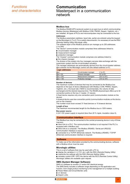
Functionsand characteristicsCommunication 0Masterpact in a communicationnetworkModbus busThe Modbus RS485 (RTU protocol) system is an open bus on which communicatingModbus devices (Masterpact with Modbus COM, PM300, Sepam, Vigilohm, etc.)are installed. All types of PLCs and microcomputers may be connected to the bus.AddressesThe Modbus parameters (address, baud rate, parity) are entered using the keypadon the Micrologic A, P or H. For a switch-disconnector, it is necessary to use the RSU(Remote Setting Utility) Micrologic utility.The software layer of the Modbus protocol can manage up to 255 addresses(1 to 255).The "device" communication module comprises three addresses linked to:b circuit-breaker managerb measurement managerb protection manager.The "chassis" communication module comprises one address linked to:b the chassis manager.The division of the system into four managers secures data exchange with thesupervision system and the circuit-breaker actuators.The manager addresses are automatically derived from the circuit-breaker address@xx entered via the Micrologic control unit (the default address is 47).Logic addresses@xx Circuit-breaker manager (1 to 47)@xx + 50 Chassis manager (51 to 97)@xx + 200 Measurement managers (201 to 247)@xx + 100 Protection manager (101 to 147)Number of devicesThe maximum number of devices that may be connected to the Modbus busdepends on the type of device (Masterpact with Modbus COM, PM500, Sepam,Vigilohm, etc.), the baud rate (19200 is recommended), the volume of dataexchanged and the desired response time. The RS485 physical layer offers up to 32connection points on the bus (1 master, 31 slaves).A fixed device requires only one connection point (communication module on thedevice).A drawout device uses two connection points (communication modules on the deviceand on the chassis).The number must never exceed 31 fixed devices or 15 drawout devices.Length of busThe maximum recommended length for the Modbus bus is 1200 meters.Bus power sourceA 24 V DC power supply is required (less than 20 % ripple, insulation class II).Communication interfaceThe Modbus bus may be connected to the central processing device in any of threemanners:b direct link to a PLC. The communication interface is not required if the PLC isequipped with a Modbus portb direct link to a computer. The Modbus (RS485) / Serial port (RS232)communication interface is requiredb connection to a TCP/IP (Ethernet) network. The Modbus (RS485) / TCP/IP(Ethernet) communication interface is required.SoftwareTo make use of the information provided by the communicating devices, softwarewith a Modbus driver must be used.Micrologic utilitiesThis is a set of software that may be used with a PC to:b display the variables (I, U, P, E, etc.) with the RDU (Remote Display Utility)b read/write the settings with the RSU (Remote Setting Utility)b remotely control (ON / OFF) the device with the RCU (Remote Control Utility).Micrologic utilities are available upon requestSMS (System Manager Software)SMS is a software to monitor LV and/or MV electrical energy.The SMS family includes a software range depending on the application andfunction, from single product monitoring to the management of a multiple building:b Power Meter and Circuit Monitor unitsb LV devicesb Sepam units.37