8 MB - POWERLAB
8 MB - POWERLAB
8 MB - POWERLAB

You also want an ePaper? Increase the reach of your titles
YUMPU automatically turns print PDFs into web optimized ePapers that Google loves.
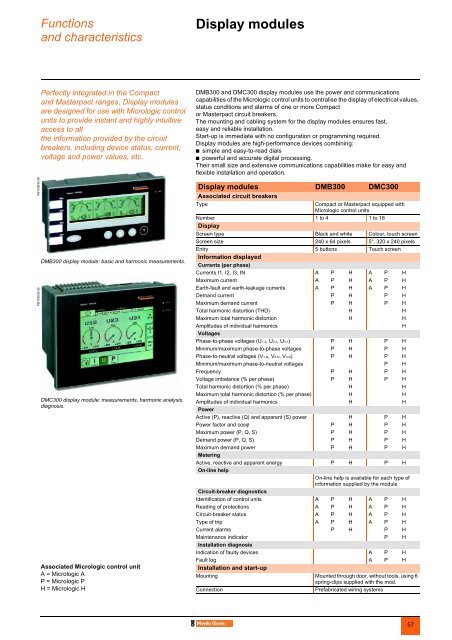
Functionsand characteristicsDisplay modules 0PB100830-58PB100832-66Perfectly integrated in the Compactand Masterpact ranges, Display modulesare designed for use with Micrologic controlunits to provide instant and highly intuitiveaccess to allthe information provided by the circuitbreakers, including device status, current,voltage and power values, etc.D<strong>MB</strong>300 display module: basic and harmonic measurements.DMC300 display module: measurements, harmonic analysis,diagnosis.Associated Micrologic control unitA = Micrologic AP = Micrologic PH = Micrologic HD<strong>MB</strong>300 and DMC300 display modules use the power and communicationscapabilities of the Micrologic control units to centralise the display of electrical values,status conditions and alarms of one or more Compactor Masterpact circuit breakers.The mounting and cabling system for the display modules ensures fast,easy and reliable installation.Start-up is immediate with no configuration or programming required.Display modules are high-performance devices combining:b simple and easy-to-read dialsb powerful and accurate digital processing.Their small size and extensive communications capabilities make for easy andflexible installation and operation.Display modules D<strong>MB</strong>300 DMC300Associated circuit breakersTypeCompact or Masterpact equipped withMicrologic control unitsNumber 1 to 4 1 to 16DisplayScreen type Black and white Colour, touch screenScreen size 240 x 64 pixels 5", 320 x 240 pixelsEntry 5 buttons Touch screenInformation displayedCurrents (per phase)Currents I1, I2, I3, IN A P H A P HMaximum current A P H A P HEarth-fault and earth-leakage currents A P H A P HDemand current P H P HMaximum demand current P H P HTotal harmonic distortion (THD) H HMaximum total harmonic distortion H HAmplitudes of individual harmonicsHVoltagesPhase-to-phase voltages (U1-2, U2-3, U3-1) P H P HMinimum/maximum phase-to-phase voltages P H P HPhase-to-neutral voltages (V1-N, V2-N, V3-N) P H P HMinimum/maximum phase-to-neutral voltages P HFrequency P H P HVoltage imbalance (% per phase) P H P HTotal harmonic distortion (% per phase) H HMaximum total harmonic distortion (% per phase) H HAmplitudes of individual harmonics H HPowerActive (P), reactive (Q) and apparent (S) power H P HPower factor and cosϕ P H P HMaximum power (P, Q, S) P H P HDemand power (P, Q, S) P H P HMaximum demand power P H P HMeteringActive, reactive and apparent energy P H P HOn-line helpOn-line help is available for each type ofinformation supplied by the moduleCircuit-breaker diagnosticsIdentification of control units A P H A P HReading of protections A P H A P HCircuit-breaker status A P H A P HType of trip A P H A P HCurrent alarms P H P HMaintenance indicator P HInstallation diagnosisIndication of faulty devices A P HFault log A P HInstallation and start-upMounting Mounted through door, without tools, using 6spring-clips supplied with the mod.ConnectionPrefabricated wiring systems57