8 MB - POWERLAB
8 MB - POWERLAB
8 MB - POWERLAB

You also want an ePaper? Increase the reach of your titles
YUMPU automatically turns print PDFs into web optimized ePapers that Google loves.
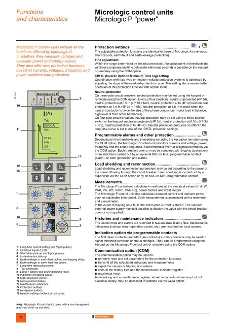
Functionsand characteristicsMicrologic control units 0Micrologic P "power"DB101485Micrologic P control units include all thefunctions offered by Micrologic A.In addition, they measure voltages andcalculate power and energy values.They also offer new protection functionsbased on currents, voltages, frequency andpower reinforce load protection.1 Long-time current setting and tripping delay.2 Overload signal (LED).3 Short-time pick-up and tripping delay.4 Instantaneous pick-up.5 Earth-leakage or earth-fault pick-up and tripping delay.6 Earth-leakage or earth-fault test button.7 Long-time rating plug screw.8 Test connector.9 Lamp + battery test and indications reset.10 Indication of tripping cause.11 High-resolution screen.12 Measurement display.13 Maintenance indicators.14 Protection settings.15 Navigation buttons.16 Hole for settings lockout pin on cover.Protection settings ....................................................... +The adjustable protection functions are identical to those of Micrologic A (overloads,short-circuits, earth-fault and earth-leakage protection).Fine adjustmentWithin the range determined by the adjustment dial, fine adjustment of thresholds (towithin one ampere) and time delays (to within one second) is possible on the keypador remotely using the COM option.IDMTL (Inverse Definite Minimum Time lag) settingCoordination with fuse-type or medium-voltage protection systems is optimised byadjusting the slope of the overload-protection curve. This setting also ensures betteroperation of this protection function with certain loads.Neutral protectionOn three-pole circuit breakers, neutral protection may be set using the keypad orremotely using the COM option, to one of four positions: neutral unprotected (4P 3d),neutral protection at 0.5 In (4P 3d + N/2), neutral protection at In (4P 4d) and neutralprotection at 1,6 In (4P 3d + 1,6N). Neutral protection at 1,6 In is used when theneutral conductor is twice the size of the phase conductors (major load imbalance,high level of third order harmonics).On four-pole circuit breakers, neutral protection may be set using a three-positionswitch or the keypad: neutral unprotected (4P 3d), neutral protection at 0.5 In (4P 3d+ N/2), neutral protection at In (4P 4d). Neutral protection produces no effect if thelong-time curve is set to one of the IDMTL protection settings.Programmable alarms and other protection..................... ....Depending on the thresholds and time delays set using the keypad or remotely usingthe COM option, the Micrologic P control unit monitors currents and voltage, power,frequency and the phase sequence. Each threshold overrun is signalled remotely viathe COM option. Each threshold overrun may be combined with tripping (protection)or an indication carried out by an optional M2C or M6C programmable contact(alarm), or both (protection and alarm).Load shedding and reconnection..........................................Load shedding and reconnection parameters may be set according to the power orthe current flowing through the circuit breaker. Load shedding is carried out by asupervisor via the COM option or by an M2C or M6C programmable contact.Measurements..........................................................................The Micrologic P control unit calculates in real time all the electrical values (V, A, W,VAR, VA, Wh, VARh, VAh, Hz), power factors and crest factors.The Micrologic P control unit also calculates demand current and demand powerover an adjustable time period. Each measurement is associated with a minimeterand a maximeter.In the event of tripping on a fault, the interrupted current is stored. The optionalexternal power supply makes it possible to display the value with the circuit breakeropen or not supplied.Histories and maintenance indicators...................................The last ten trips and alarms are recorded in two separate history files. Maintenanceindications (contact wear, operation cycles, etc.) are recorded for local access.Indication option via programmable contactsThe M2C (two contacts) and M6C (six contacts) auxiliary contacts may be used tosignal threshold overruns or status changes. They can be programmed using thekeypad on the Micrologic P control unit or remotely using the COM option.Communication option (COM)The communication option may be used to:b remotely read and set parameters for the protection functionsb transmit all the calculated indicators and measurementsb signal the causes of tripping and alarmsb consult the history files and the maintenance-indicator register.b maximeter reset.An event log and a maintenance register, stored in control-unit memory but notavailable locally, may be accessed in addition via the COM option.Note: Micrologic P control units come with a non-transparentlead-seal cover as standard.26