8 MB - POWERLAB
8 MB - POWERLAB
8 MB - POWERLAB

Create successful ePaper yourself
Turn your PDF publications into a flip-book with our unique Google optimized e-Paper software.
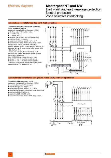
Electrical diagrams Masterpact NT and NW 0Earth-fault and earth-leakage protectionNeutral protectionZone selective interlockingExternal sensor (CT) for residual earth-fault protectionConnection of current-transformer secondarycircuit for external neutralMasterpact equipped with a Micrologic 6 A/P/H:b shielded cable with 2 twisted pairsb T1 twisted with T2b T3 twisted with T4b shielding connected to GND on one end onlyb maximum length 10 metersb cable cross-sectional area 0.4 to 1.5 mm 2b recommended cable: Belden 9552 or equivalent.If supply is via the top, follow the shematics.If supply is via the bottom, control wiring is identical; forthe power wiring, H1 is connected to the source side,H2 to the load side.For four-pole versions, for residual earth-faultprotection, the current transformer for the externalneutral is not necessary.If the 2000/6300 current transformer is used:b signals T1 and T2 must be wired in seriesb signals T3 and T4 must be wired in parallel.Connection for signal VN is required only for powermeasurements (3 Ø, 4 wires, 4CTs).DB101413External transformer for source ground return (SGR) earth-fault protectionConnection of the secondary circuitMasterpact equipped with a Micrologic 6 A/P/H:b unshielded cable with 1 twisted pairb maximum length 150 metersb cable cross-sectional area 0.4 to 1.5 mm 2b terminals 5 and 6 may not be used at the same timeb use terminal 5 for NW08 to 40b use terminal 6 for NW40b to 63b recommended cable: Belden 9409 or equivalent.DB10219194