8 MB - POWERLAB
8 MB - POWERLAB
8 MB - POWERLAB

You also want an ePaper? Increase the reach of your titles
YUMPU automatically turns print PDFs into web optimized ePapers that Google loves.
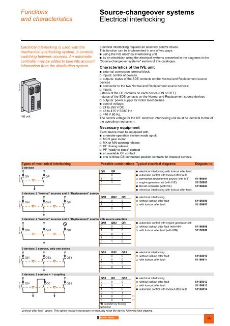
Functionsand characteristicsSource-changeover systems 0Electrical interlockingDB101573Electrical interlocking is used with themechanical interlocking system. It controlsswitching between sources. An automaticcontroller may be added to take into accountinformation from the distribution system.IVE unit.Electrical interlocking requires an electrical control device.This function can be implemented in one of two ways:b using the IVE electrical interlocking unitb by an electrician using the electrical systems presented in the diagrams in the"Source-changeover systems" section of this catalogue.Characteristics of the IVE unitb external connection terminal block:v inputs: control of devicesv outputs: status of the SDE contacts on the Normal and Replacement sourcedevicesb connector to the two Normal and Replacement source devices:v inputs:- status of the OF contacts on each device (ON or OFF)- status of the SDE contacts on the Normal and Replacement source devicesv outputs: power supply for motor mechanismsb control voltage:v 24 to 250 V DCv 48 to 415 V 50/60 Hzv 440 V 60 Hz.The control voltage for the IVE electrical interlocking unit must be identical to that ofthe operating mechanism.Necessary equipmentEach device must be equipped with:b a remote-operation system made up of:v MCH gear motorv MX or MN opening releasev XF closing releasev PF "ready to close" contactb an available OF contactb one to three CE connected-position contacts for drawout devices.DB101574DB101575Types of mechanical interlocking Possible combinations Typical electrical diagrams Diagram no.2 devicesQN QR b electrical interlocking with lockout after fault:0 0 b automatic control with lockout after fault:1 0 v permanent replacement source (with IVE) 511569040 1 v engine generator set (with IVE) 51156905b BA/UA controller (with IVE) 51156903b electrical interlocking with lockout after fault:3 devices: 2 “Normal” sources and 1 “Replacement” sourceQN1 QN2 QR b electrical interlocking:0 0 0 v without lockout after fault 511569061 1 0 v with lockout after fault 511569070 0 1DB1015763 devices: 2 “Normal” sources and 1 “Replacement” source with source selectionQN1 QN2 QR b automatic control with engine generator set:0 0 0 v without lockout after fault (with MN) 511569081 0 0 v with lockout after fault (with MN) 511569090 0 11 1 00 1 0DB1015773 devices: 3 sources, only one deviceQS1 QS2 QS3 b electrical interlocking:0 0 0 v without lockout after fault 511569101 0 0 v with lockout after fault 511569110 1 00 0 13 devices: 2 sources + 1 couplingQS1 QC QS2 b electrical interlocking:0 0 0 v without lockout after fault 511569121 0 1 v with lockout after fault 511569131 1 0 b automatic control with lockout after fault 511569140 1 11 0 0(1)0 0 1(1)(1) possible by forcingoperation“Lockout after fault” option. This option makes it necessary to manually reset the device following fault tripping.DB10157855