MCHXXX Control Handle Technical Information ©Sauer-Danfoss
MCHXXX Control Handle Technical Information ©Sauer-Danfoss
MCHXXX Control Handle Technical Information ©Sauer-Danfoss

You also want an ePaper? Increase the reach of your titles
YUMPU automatically turns print PDFs into web optimized ePapers that Google loves.
<strong>MCHXXX</strong> <strong>Control</strong> <strong>Handle</strong><br />
<strong>Technical</strong> <strong>Information</strong><br />
Wiring <strong>Information</strong><br />
Wiring A barrier terminal strip inside the handle’s case provides connections to power, ground,<br />
and potentiometers when no external cable is ordered. Run a cable from the strip<br />
through the strain relief provided on the side or bottom of the case. Reference<br />
Center-Off Switch Assembly and Wiring Connections for the <strong>Control</strong> <strong>Handle</strong>, page 11.<br />
A clockwise handle movement causes a current flow from terminal B to A when the<br />
terminal strip is facing you.<br />
14 11022667 • Rev EA • Jan 2011<br />
WWarning<br />
An unforeseen failure may cause an output which could activate a valve or pump. If<br />
this occurs, the vehicle or mechanism may move, possibly endangering people or<br />
equipment. Equip handles with a center-off switch to mitigate this condition. For cases<br />
in which an active neutral is necessary, you must provide an operator-presence interlock<br />
and/or braking system sufficient to stop and hold the system or vehicle should this<br />
condition develop.<br />
In most applications, auxiliary switches must be customer-wired, as shown in Center-<br />
Off Switch Assembly and Wiring Connections for the <strong>Control</strong> <strong>Handle</strong>, page 11. When the<br />
switch is used as a center-off, power is connected from the external 12 Volt supply to the<br />
terminal labeled common. The switch terminals are 3/16 inch quick-connect. Phasing and<br />
Color Scheme for <strong>Handle</strong> with Cable and Connector, page 11, shows a pre-wired control<br />
handle with center-off switch and Delphi connector, exhibiting the handle phasing and<br />
color coding of the wires.<br />
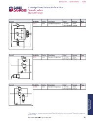
The Unsealed Delphi Mating Connector Assembly below demonstrates how to assemble<br />
the mating Delphi connector (male shell, female sockets) used in Phasing and Color<br />
Scheme for <strong>Handle</strong> with Cable and Connector, page 11. The necessary parts are shipped<br />
in a bag assembly (part number K03370) composed of six sockets and one plastic<br />
connector body.<br />
Unsealed Delphi Mating Connector Assembly<br />
Trim Terminal As Shown (2)<br />
Shroud (Ref) Terminals (6) (Ref )<br />
Insulation Crimp*<br />
Leadwire Crimp*<br />
* Crimp before inserting terminal into body<br />
1137B<br />
For optional connectors, contact your Sauer-<strong>Danfoss</strong> representative.