MCHXXX Control Handle Technical Information ©Sauer-Danfoss
MCHXXX Control Handle Technical Information ©Sauer-Danfoss
MCHXXX Control Handle Technical Information ©Sauer-Danfoss

You also want an ePaper? Increase the reach of your titles
YUMPU automatically turns print PDFs into web optimized ePapers that Google loves.
<strong>MCHXXX</strong><br />
<strong>Control</strong> <strong>Handle</strong><br />
<strong>Technical</strong><br />
<strong>Information</strong>
Version<br />
<strong>MCHXXX</strong> <strong>Control</strong> <strong>Handle</strong><br />
<strong>Technical</strong> <strong>Information</strong><br />
Revisions<br />
Revisions<br />
2 11022667 • Rev EA • Jan 2011<br />
Date Page Changed Rev.<br />
03 Jan, 2011 12 Added new line item to table and deleted a line item EA<br />
14 May, 2010 12 <strong>MCHXXX</strong> Potentiometer Models with 1K Ohm table updated. DA<br />
03 Feb, 2010 12 <strong>MCHXXX</strong> Potentiometer Models with 1K Ohm table updated. CA<br />
10 Aug, 2009 12 <strong>MCHXXX</strong> Potentiometer Models with 1K Ohm table updated. BA<br />
30 Jan, 2009 13 Corrected operating and storage temperature. AB<br />
18 Dec, 2008 Various pages Updated BLN-95-8956 to <strong>Technical</strong> <strong>Information</strong> (TI) format; and<br />
various content updated.<br />
© 2011 Sauer-<strong>Danfoss</strong>. All rights reserved.<br />
Sauer-<strong>Danfoss</strong> accepts no responsibility for possible errors in catalogs, brochures and other printed material.<br />
Sauer -<strong>Danfoss</strong> reserves the right to alter its products without prior notice. This also applies to products<br />
already ordered provided that such alterations can be made without affecting agreed specifications. All<br />
trademarks in this material are properties of their respective owners. Sauer-<strong>Danfoss</strong>, the Sauer-<strong>Danfoss</strong><br />
logotype, the Sauer-<strong>Danfoss</strong> S-icon, PLUS+1, what really matters is inside® and Know-How in Motion are<br />
trademarks of the Sauer-<strong>Danfoss</strong> Group.<br />
AA<br />
Front cover illustrations: F101733, F101732, F101731, 2452, 2453
<strong>MCHXXX</strong> <strong>Control</strong> <strong>Handle</strong><br />
<strong>Technical</strong> <strong>Information</strong><br />
Contents<br />
Product Overview Description ....................................................................................................................................................... 4<br />
Features ............................................................................................................................................................. 4<br />
Ordering <strong>Information</strong>.................................................................................................................................... 4<br />
Mounting ..................................................................................................................................................... 6<br />
Type of <strong>Control</strong> Knob............................................................................................................................... 6<br />
<strong>Handle</strong> Actuation ...................................................................................................................................... 7<br />
Electrical Characteristics ......................................................................................................................... 7<br />
Connector .................................................................................................................................................... 8<br />
Suffix number ............................................................................................................................................. 8<br />
Dimensions ....................................................................................................................................................... 9<br />
Connectors ....................................................................................................................................................... 9<br />
<strong>Technical</strong> Data Specifications .................................................................................................................................................10<br />
Connection Diagrams ................................................................................................................................11<br />
Potentiometer Option ..........................................................................................................................11<br />
Potentiometer Option with 1K Ohm Potentiometer ................................................................12<br />
PWM Option (primarily) ........................................................................................................................13<br />
Environmental Testing ................................................................................................................................13<br />
Wiring <strong>Information</strong> Wiring ...............................................................................................................................................................14<br />
Device Repair Return To .........................................................................................................................................................16<br />
11022667 • Rev EA • Jan 2011<br />
3
Description<br />
<strong>MCHXXX</strong> <strong>Control</strong> <strong>Handle</strong><br />
<strong>Technical</strong> <strong>Information</strong><br />
Product Overview<br />
4 11022667 • Rev EA • Jan 2011<br />
The <strong>MCHXXX</strong> Single Axis <strong>Control</strong> <strong>Handle</strong> provides remote electrical actuation of<br />
Sauer-<strong>Danfoss</strong> pumps/motors, and or other electrically-actuated pump strokers for<br />
open loop control systems. The <strong>MCHXXX</strong> can function as a setpoint for analog or<br />
microprocessor-controlled systems for controlling position, speed, pressure, horsepower<br />
or other dynamic parameters.<br />
Features Shock and vibration resistant<br />
Choice of three mounting styles, with or without watertight case<br />
Rugged components designed for the construction environment<br />
High-torque handle actuation gives sure feel<br />
Simple to install<br />
Mechanical options include center-lock, spring-return, friction drag, uni/bi-directionality<br />
and optional wire harness with a variety of electrical connectors<br />
Electrical characteristics customized to the application<br />
Ordering <strong>Information</strong> A wide range of options to the basic control handle allow custom-tailoring to each<br />
application. See the Ordering Specification Chart, page 5, for assistance in determining<br />
model number. Other options are possible; consult Sauer-<strong>Danfoss</strong> with further<br />
questions.
Ordering <strong>Information</strong><br />
(continued)<br />
For details regarding<br />
unique configurations,<br />
contact your Sauer-<strong>Danfoss</strong><br />
representative.<br />
<strong>MCHXXX</strong> <strong>Control</strong> <strong>Handle</strong><br />
<strong>Technical</strong> <strong>Information</strong><br />
Product Overview<br />
Ordering Specification Chart<br />
MCH X X X X X XXX<br />
Mounting<br />
Code Description<br />
1 Base (surface) mount aluminum case<br />
2 Top mount (drop in) with plastic case<br />
3 Top mount (drop in) without case<br />
4 Panel mount with plastic case<br />
5 Panel mount without case<br />
Type of <strong>Control</strong> Knob<br />
Code Description<br />
1 Non-locking<br />
2 Center lock<br />
3 Non-locking, auxiliary push button switch<br />
5 Non-locking, no knob<br />
6 Three position maintained rocker switch<br />
8 ** Special<br />
(no handle or knob)<br />
9 Three position momentary rocker switch<br />
** Unique configuration.<br />
<strong>Handle</strong> Actuation<br />
Code Description<br />
Mounting Type of<br />
<strong>Control</strong> Knob<br />
A Spring return, bi-directional<br />
B Friction held, bi-directional<br />
C Friction held, uni-directional<br />
D Special<br />
(friction held, center detent only, no brake)<br />
11022667 • Rev EA • Jan 2011<br />
<strong>Handle</strong><br />
Actuation<br />
Electrical<br />
Characteristics<br />
Electrical Characteristics<br />
Code Description<br />
A Proportional, no switches, 12 Vdc<br />
B Proportional, center off switch, 12 Vdc,<br />
C Proportional, center off switch, 24 Vdc<br />
D Proportional, center off and auxiliary<br />
switch, 12 Vdc<br />
E Proportional, set-point potentiometer,<br />
12 Vdc<br />
F Step-plus-proportional, 12 Vdc<br />
G Step-plus-proportional, 24 Vdc<br />
H Switching<br />
J Step-plus-proportional, full auxiliary<br />
switching, 12 Vdc<br />
K Proportional, unwired switch<br />
L* Electronic PWM auxiliary switching,<br />
12 Vdc<br />
M Proportional, three switches<br />
X** Special<br />
Y** Special<br />
Z** Special<br />
* Option L will no longer be available starting in<br />
2008 as it nears the end of its life cycle.<br />
** Unique configuration.<br />
Connector<br />
Code Description<br />
1 Terminal strip<br />
Connector Factory<br />
Assigned<br />
2 Pigtail 1524 mm [60 in] without connector<br />
3 Pigtail with unsealed Delphi connector<br />
6 Pigtail with sealed Delphi connector,<br />
4 pin male and female<br />
7 Pigtail sealed Delphi connector<br />
8 Pigtail sealed Deutsch® connector<br />
5
Ordering <strong>Information</strong><br />
(continued)<br />
<strong>MCHXXX</strong> <strong>Control</strong> <strong>Handle</strong><br />
<strong>Technical</strong> <strong>Information</strong><br />
Product Overview<br />
6 11022667 • Rev EA • Jan 2011<br />
Mounting<br />
1 Base (surface) mount aluminum case<br />
Four screws connect to the flanges on the bottom of the metal case.<br />
2 Top mount with (drop in) with plastic case<br />
Two screws connect to an enlarged mounting plate. Top mounting allows the entire<br />
handle to be removed from above the panel. The case is made of black nylon plastic.<br />
3 Top mount (drop in) without case<br />
Two screws connect to an enlarged mounting plate. Top mounting allows the entire<br />
handle to be removed from above the panel.<br />
4 Panel mount with plastic case<br />
Four screws connect to the top plate that holds the boot in place. The case is made of<br />
black nylon plastic.<br />
5 Panel mount without case<br />
Four screws connect to the top plate that holds the boot in place.<br />
Type of <strong>Control</strong> Knob<br />
Reference Dimensions, page 9.<br />
1 Non-locking<br />
The non-locking handle has a standard ball knob. The friction-held handle detents with<br />
a spring-loaded ball to indicate null, while the spring-return handle has a spring preload<br />
indicating null.<br />
2 Center lock<br />
The center lock handle has a cylindrical knob and provides a positive center lock that<br />
unlatches when the operator pulls up on the knob.<br />
3 Non-locking, auxiliary push-button switch<br />
This knob is teardrop shaped, with an auxiliary momentary push-button switch on top.<br />
The switch is wired through the handle shaft to the body with three wires (common,<br />
normally open, and normally closed).<br />
5 Non-locking, no knob<br />
The customer provides customized knob.<br />
6 Three position maintained rocker switch<br />
The cylindrical knob has a boot covering the three-position switch in the knob. The<br />
switch, wired through the handle, is used for auxiliary functions.<br />
9 Three position momentary rocker switch<br />
This is the same as option 6, but the switch returns to the center position when released.
Ordering <strong>Information</strong><br />
(continued)<br />
<strong>MCHXXX</strong> <strong>Control</strong> <strong>Handle</strong><br />
<strong>Technical</strong> <strong>Information</strong><br />
Product Overview<br />
<strong>Handle</strong> Actuation<br />
A Spring return, bi-directional<br />
This handle uses a torsion spring to return to the mechanical center position and has 30<br />
degrees of handle throw on either side of center.<br />
B Friction held, bi-directional<br />
This handle has an adjustable drag, set with a clamp-type brake that holds the handle at<br />
the set position and has 30 degrees of handle throw on either side of the center detent.<br />
C Friction held, uni-directional<br />
This handle has 60 degrees of high-resolution of handle throw, rotating on only one side<br />
of mechanical null, which is at full stroke. It has no detent mechanism.<br />
Electrical Characteristics<br />
A Proportional, no switches, 12 Vdc<br />
This handle’s output curve is fairly linear, with output voltage as a function of handle<br />
stroke (see Proportional <strong>Control</strong> <strong>Handle</strong>, page 9). The supply voltage is 12 Volts, and there<br />
are no auxiliary function switches.<br />
B Proportional, center-off switch, 12 Vdc<br />
This handle has a center-off switch that ensures zero output voltage within ±3 degrees<br />
of handle center position.<br />
C Proportional, center-off switch, 24 Vdc<br />
Same as option B except this handle runs on a supply voltage of 24 Volts.<br />
D Proportional, center-off and auxiliary switch, 12 Vdc<br />
Same as option B except this handle has a second switch that actuates at +2 or<br />
-2 degrees.<br />
E Proportional, set-point potentiometer, 12 Vdc<br />
Same as option B except this handle maintains the same polarity of signal in forward<br />
or reverse.<br />
F Step-plus-proportional, 12 Vdc<br />
This handle uses two switches to give the step-plus-proportional output current on<br />
either side of null. This overcomes deadbands in spool valves (see Step-Plus-Proportional-<br />
<strong>Control</strong>-<strong>Handle</strong> PWM <strong>Handle</strong>, page 10). Current beyond this step output is proportional<br />
through the rest of the handle throw. Full current output at 30 degrees handle stroke is<br />
maximum of 250 mA. Step current is a maximum of 50% of full current output.<br />
G Step-plus-proportional, 24 Vdc<br />
Same as option F, except this handle runs on a supply voltage of 24 Vdc.<br />
H Switching<br />
This handle is non-proportional. Moving the handle off null activates switches that<br />
power ON/OFF devices (solenoid valves for example).<br />
J Step-plus-proportional, full auxiliary switching, 12 Vdc<br />
This handle uses the step switches for additional secondary functions. Full current<br />
output at 30 degrees handle stroke is a maximum of 250 mA. Step current is a maximum<br />
of 50% of full current output.<br />
11022667 • Rev EA • Jan 2011<br />
7
Ordering <strong>Information</strong><br />
(continued)<br />
Option L will no longer be<br />
available starting in 2008<br />
as it nears the end of its<br />
life cycle.<br />
For optional connectors,<br />
contact your Sauer-<strong>Danfoss</strong><br />
representative.<br />
Pigtail (or leadwire) are<br />
routed from the control<br />
handle to a Delphi<br />
environmental connector.<br />
Pigtail minimum length is<br />
381 mm [15 in].<br />
For details regarding<br />
unique configurations,<br />
contact your Sauer-<strong>Danfoss</strong><br />
representative.<br />
<strong>MCHXXX</strong> <strong>Control</strong> <strong>Handle</strong><br />
<strong>Technical</strong> <strong>Information</strong><br />
Product Overview<br />
8 11022667 • Rev EA • Jan 2011<br />
K Proportional, unwired switch<br />
The customer uses the unwired center switch to operate an auxiliary function, such as<br />
neutral start interlock.<br />
L Electronic PWM auxiliary switching, 12 Vdc<br />
This handle uses a printed circuit board that makes the step height and output<br />
current fully adjustable, accommodating high current applications. It also has pulse<br />
width modulation, that dithers the output to overcome hydraulic valve stiction. Full<br />
current output at 30 degrees handle stroke is a maximum of 2 Amps into a 5 Ohm<br />
load. Step current is a maximum 50% of full current output. Typical dither frequencies<br />
(dependent on resistance of the load, specified in the suffix number) are: 60 Hz for the<br />
HPI solenoid actuator, approximately 400 Hz for the V7058 Hydrotransmission Valve and<br />
approximately 1000 Hz for the MCV101A/ MCV116A Pressure <strong>Control</strong> Pilot Valve.<br />
M Proportional, three switches<br />
The three switches are: a wired center switch, one unwired switch in forward and one<br />
unwired switch in reverse.<br />
There are either 3 or 4 trim potentiometers depending on the specific <strong>MCHXXX</strong> model.<br />
Reference <strong>Handle</strong> Adjustments, page 14.<br />
Connector<br />
1 Terminal strip<br />
Electrical connections are made to a set of four internal or more screw terminals<br />
depending on the specific model.<br />
2 Pigtail 1524 mm [60 in] without connector<br />
Four wires extend from the handle case. Reference Phasing and Color Scheme for <strong>Handle</strong><br />
with Cable and Connector, page 11 for lengths.<br />
3 Pigtail with unsealed Delphi connector<br />
The wires from the case terminate in a Delphi environmental connector. Reference<br />
Phasing and Color Scheme for <strong>Handle</strong> with Cable and Connector, page 11.<br />
6 Pigtail with sealed Delphi connector, 4 pin male and female<br />
There are two separate connectors, each connects to a separate potentiometer.<br />
7 Pigtail sealed Delphi connector<br />
The wires from the case terminate in a sealed Delphi connector.<br />
8 Pigtail sealed Deutsch connector<br />
The wires from the case terminate in a sealed Deutsch connector.<br />
Suffix number<br />
The factory generates these final three numbers. To create the suffix number, supply<br />
the following information: supply voltage, number of additional switches needed and<br />
actuation angle of each with respect to null, full current output, resistance of the driven<br />
load, and step current needed (if necessary).
<strong>MCHXXX</strong> <strong>Control</strong> <strong>Handle</strong><br />
<strong>Technical</strong> <strong>Information</strong><br />
Product Overview<br />
Dimensions <strong>MCHXXX</strong> <strong>Control</strong> <strong>Handle</strong> Mounting Dimensions in mm [in]<br />
63.76 max.<br />
[2.51]<br />
50.8 ± 0.4<br />
[2.0]<br />
Customer<br />
panel<br />
6.35<br />
[0.25]<br />
6.35<br />
[0.25]<br />
149.1 max. [5.87]<br />
136.4 ± 0.4 [5.37]<br />
7.1 (4)<br />
[0.279]<br />
Connectors 3 or 4 pin Delphi Connector<br />
A<br />
B<br />
C<br />
D<br />
31.75<br />
[1.25]<br />
85.5 max.<br />
[3.37]<br />
Power +<br />
Speed<br />
Ground<br />
Direction<br />
11022667 • Rev EA • Jan 2011<br />
Panel cutout and<br />
mounting plate<br />
3524A<br />
138.0<br />
[5.43]<br />
124.0 [4.88]<br />
150.5 max. [5.93]<br />
Customer<br />
panel<br />
60.4<br />
[2.38]<br />
7.0<br />
[0.275]<br />
33.3<br />
[1.31]<br />
66.6<br />
[2.62]<br />
4.5 ± 0.008 [2.0]<br />
Mounting plate<br />
113 max.<br />
[4.45]<br />
29.5 [1.16]<br />
251.5 max.<br />
[9.9]<br />
Customer<br />
panel<br />
50.8<br />
[2.0]<br />
Mounting plate<br />
30º ref. 30º ref. 30º ref. 30º ref. 30º ref. 30º ref. 30º ref. 30º ref.<br />
302.0 max.<br />
[11.88]<br />
96.0 max.<br />
[3.78]<br />
120.0 max.<br />
[4.72]<br />
121.0 max. [4.76] 14.2<br />
[0.56]<br />
121.0 max. [4.76]<br />
Surface mount<br />
120.0 max.<br />
[4.72]<br />
27.0<br />
[1.06]<br />
269.2 max.<br />
[10.6]<br />
29.5 max.<br />
[1.16]<br />
25.4<br />
[1.0]<br />
50.8<br />
[2.0]<br />
121.3 max. [4.78] 121.3 max. [4.78]<br />
Top (drop in)<br />
mount<br />
Tapping<br />
screws<br />
(2)<br />
25.4<br />
[1.0]<br />
54.0<br />
[2.12]<br />
6.2 (4)<br />
[0.245]<br />
Remove burrs<br />
from both sides of panel<br />
to avoid damaging boot<br />
149.9 max.<br />
[5.9]<br />
Remove collar<br />
that retains boot<br />
and discard<br />
97.6 max.<br />
[3.84]<br />
114.6<br />
max.<br />
[4.51]<br />
60.4<br />
29.5 [1.16]<br />
44.4<br />
[2.38]<br />
64.1 max.<br />
[2.52]<br />
[1.75]<br />
Panel mount Side view<br />
of all<br />
panel mount<br />
4 pin Deutsch Plug DT Series Connector<br />
A<br />
Power +<br />
B<br />
Speed<br />
For optional connectors, contact your Sauer-<strong>Danfoss</strong> representative.<br />
C<br />
Ground<br />
D<br />
Direction<br />
3525<br />
1135D<br />
9
Specifications Electrical<br />
PWM <strong>MCHXXX</strong> option<br />
will no longer be available<br />
starting in 2008 as it nears<br />
the end of its life cycle.<br />
<strong>MCHXXX</strong> <strong>Control</strong> <strong>Handle</strong><br />
<strong>Technical</strong> <strong>Information</strong><br />
<strong>Technical</strong> Data<br />
Operating voltage<br />
Power*<br />
Load resistance*<br />
10 11022667 • Rev EA • Jan 2011<br />
11 to 15 Vdc (12 Volt models)<br />
22 to 30 Vdc (24 Volt models)<br />
Switch current capability 3 Amps inductive at 28 Vdc<br />
* Customer specified. Reference Ordering <strong>Information</strong>, page 5.<br />
Mechanical<br />
<strong>Handle</strong> stroke ± 30º<br />
Spring torque<br />
Detent torque (over and above friction drag) 1.1 N•m [10 lbf•in]<br />
Friction drag<br />
Step-Plus-Proportional <strong>Control</strong> <strong>Handle</strong><br />
PWM Option<br />
Output current<br />
Dual-range<br />
adjust option<br />
Adjustable<br />
handle stroke<br />
Adjustable<br />
1140B<br />
1.2±.4 N•m [11±4 lbf•in] at center breakaway<br />
2.0±.7 N•m [18±6 lbf•in] at full stroke<br />
1.5±.3 N•m [13.5±3 lbf•in]<br />
Friction is adjusted at the brake with a 5/32 inch internal<br />
hex wrench and 3/8 inch open-end hex wrench<br />
Proportional <strong>Control</strong> <strong>Handle</strong><br />
Potentiometer Option<br />
Output current<br />
30° 30°<br />
<strong>Handle</strong> stroke<br />
1139A
Connection Diagrams<br />
Center-off switch assembly<br />
and wiring connections for<br />
the control handle.<br />
<strong>MCHXXX</strong> <strong>Control</strong> <strong>Handle</strong><br />
<strong>Technical</strong> <strong>Information</strong><br />
<strong>Technical</strong> Data<br />
Potentiometer Option<br />
Direct EDC <strong>Control</strong><br />
+<br />
A<br />
B<br />
-<br />
Ground<br />
<strong>MCHXXX</strong> potentiometer models having either two or single 200 Ohm pots are<br />
configured to directly control Sauer-<strong>Danfoss</strong> variable pumps with electrical displacement<br />
controls (EDCs). Whether two or single pots, both require the same electrical connection<br />
to the EDC and only one of the dual coils needs to be connected to achieve forward and<br />
reverse pump flow.<br />
11022667 • Rev EA • Jan 2011<br />
NC<br />
COM NO<br />
From Potentiometer +<br />
From +<br />
Torque Motor<br />
EDC<br />
A B<br />
12 or 24 Vdc<br />
1224B<br />
11
Connection Diagrams<br />
(continued)<br />
<strong>MCHXXX</strong> Potentiometer Models with 1K Ohm<br />
Material Number Centerlock<br />
<strong>MCHXXX</strong> <strong>Control</strong> <strong>Handle</strong><br />
<strong>Technical</strong> <strong>Information</strong><br />
<strong>Technical</strong> Data<br />
12 11022667 • Rev EA • Jan 2011<br />
Potentiometer Option with 1K Ohm Potentiometer<br />
Analog Setpoint <strong>Control</strong>ler Input<br />
RED<br />
GRN<br />
BLK<br />
( + ) A ( − )<br />
Ground<br />
PLUS+1 controller<br />
5 Vdc supply 2464<br />
<strong>MCHXXX</strong> potentiometer models having a 1K Ohm pot are commonly used as analog<br />
input to a controller (for example, SX or PLUS+1 MC200 <strong>Control</strong>lers). The supply voltage<br />
(5 Vdc sensor supply) is usually supplied from the controller.<br />
Spring<br />
return<br />
Friction<br />
hold<br />
5 Vdc<br />
supply<br />
A D<br />
B C<br />
Terminal<br />
strip<br />
Torque motor<br />
MCH11CB1510 X X X X<br />
Microswitches<br />
Forward Neutral Reverse<br />
11046484 MCH12AR1642 X X X X X X<br />
10106017 MCH21CB1510 X X X X<br />
11048497 MCH22AA1644 X X X X<br />
11068164 MCH22BB1648 X X X X X<br />
MCH28BM1493<br />
(No knob)<br />
MCH4FBD1505<br />
(Operator presence)<br />
X X X XX<br />
(2 switches)<br />
X<br />
X X X X X<br />
MCH41BM1504 X X X X X X<br />
MCH43BD1499<br />
(Push button)<br />
X X X X X<br />
MCH51AM1497 X X X X X X<br />
MCH51AR1509 X X X X X X<br />
11017769 MCH51BB1535 X X X X<br />
MCH51BD1517 X X X X X<br />
MCH52BM1497 X X X X X X X<br />
MCH52BM1514 X X X X X X X<br />
11090431 MCH19AM1649 X X X X X X
Connection Diagrams<br />
(continued)<br />
PWM <strong>MCHXXX</strong> option<br />
will no longer be available<br />
starting in 2008 as it nears<br />
the end of its life cycle.<br />
Environmental Testing<br />
<strong>MCHXXX</strong> <strong>Control</strong> <strong>Handle</strong><br />
<strong>Technical</strong> <strong>Information</strong><br />
<strong>Technical</strong> Data<br />
PWM Option (primarily)<br />
Phasing and Color Scheme for <strong>Handle</strong> with Cable and Connector<br />
The blue and yellow<br />
wires provide optional<br />
functions.<br />
Performance<br />
Null current<br />
11022667 • Rev EA • Jan 2011<br />
Reverse Forward<br />
Center deadband (optional) ±3º nominal<br />
Full stroke current capability*<br />
Blue<br />
Red<br />
Yellow<br />
Green<br />
White<br />
Black<br />
Powered when handle is centered<br />
12 or 24 Vdc supply<br />
Powered when handle is off center<br />
Valve drive, handle forward<br />
Valve drive, handle reverse<br />
Ground<br />
304.8 mm [15 in] (cable length with connector)<br />
1524 mm [5 ft] (cable length without connector)<br />
±5 mA maximum if not switched (12 Vdc models)<br />
±8 mA maximum if not switched (24 Vdc models)<br />
Step current* Step current occurs at end of deadband.<br />
* Customer specified. Reference Ordering <strong>Information</strong>, page 5.<br />
Temperature<br />
Operating -34º to 66ºC [-30º to 150ºF]<br />
Storage -40º to 77ºC [-40º to 170ºF]<br />
Humidity<br />
After being placed in a controlled atmosphere of 95% humidity at 38ºC [100ºF] for 10 days, the control handle<br />
performs normally.<br />
Rain<br />
After being showered from all directions by a high pressure hose, the control handle performs normally<br />
(applied to cased models only). This test fulfills NEMA 4 specifications (IP 65 equivalent).<br />
Vibration<br />
Withstands a vibration test designed for mobile equipment controls consisting of two parts:<br />
1. Cycling from 5 to 2000 Hz in each of the 3 axes.<br />
2. Resonance dwell for one million cycles for each resonance point in each of the 3 axes.<br />
NEMA (National Electrical Manufacturer Association) NEMA 4 = Intended for indoor or<br />
outdoor use primarily to provide a degree of protection against windblown dust and<br />
rain, splashing water, hose-directed water and external ice formation.<br />
1136B<br />
13
<strong>MCHXXX</strong> <strong>Control</strong> <strong>Handle</strong><br />
<strong>Technical</strong> <strong>Information</strong><br />
Wiring <strong>Information</strong><br />
Wiring A barrier terminal strip inside the handle’s case provides connections to power, ground,<br />
and potentiometers when no external cable is ordered. Run a cable from the strip<br />
through the strain relief provided on the side or bottom of the case. Reference<br />
Center-Off Switch Assembly and Wiring Connections for the <strong>Control</strong> <strong>Handle</strong>, page 11.<br />
A clockwise handle movement causes a current flow from terminal B to A when the<br />
terminal strip is facing you.<br />
14 11022667 • Rev EA • Jan 2011<br />
WWarning<br />
An unforeseen failure may cause an output which could activate a valve or pump. If<br />
this occurs, the vehicle or mechanism may move, possibly endangering people or<br />
equipment. Equip handles with a center-off switch to mitigate this condition. For cases<br />
in which an active neutral is necessary, you must provide an operator-presence interlock<br />
and/or braking system sufficient to stop and hold the system or vehicle should this<br />
condition develop.<br />
In most applications, auxiliary switches must be customer-wired, as shown in Center-<br />
Off Switch Assembly and Wiring Connections for the <strong>Control</strong> <strong>Handle</strong>, page 11. When the<br />
switch is used as a center-off, power is connected from the external 12 Volt supply to the<br />
terminal labeled common. The switch terminals are 3/16 inch quick-connect. Phasing and<br />
Color Scheme for <strong>Handle</strong> with Cable and Connector, page 11, shows a pre-wired control<br />
handle with center-off switch and Delphi connector, exhibiting the handle phasing and<br />
color coding of the wires.<br />
The Unsealed Delphi Mating Connector Assembly below demonstrates how to assemble<br />
the mating Delphi connector (male shell, female sockets) used in Phasing and Color<br />
Scheme for <strong>Handle</strong> with Cable and Connector, page 11. The necessary parts are shipped<br />
in a bag assembly (part number K03370) composed of six sockets and one plastic<br />
connector body.<br />
Unsealed Delphi Mating Connector Assembly<br />
Trim Terminal As Shown (2)<br />
Shroud (Ref) Terminals (6) (Ref )<br />
Insulation Crimp*<br />
Leadwire Crimp*<br />
* Crimp before inserting terminal into body<br />
1137B<br />
For optional connectors, contact your Sauer-<strong>Danfoss</strong> representative.
Wiring (continued)<br />
PWM <strong>MCHXXX</strong> option<br />
will no longer be available<br />
starting in 2008 as it nears<br />
the end of its life cycle.<br />
Option L will no longer be<br />
available starting in 2008<br />
as it nears the end of its<br />
life cycle.<br />
<strong>MCHXXX</strong> <strong>Control</strong> <strong>Handle</strong><br />
<strong>Technical</strong> <strong>Information</strong><br />
Wiring <strong>Information</strong><br />
PWM <strong>MCHXXX</strong> option models are fitted with trim potentiometers for adjusting the<br />
output current. <strong>MCHXXX</strong> PWM Option with Trim Potentiometer Configurations, below<br />
shows the location of the three trim potentiometers on the L handle. There are either 3<br />
or 4 trim potentiometers depending on the specific <strong>MCHXXX</strong> model. Reference Electrical<br />
Characteristics, M Proportional, three switches, page 8.<br />
WCaution<br />
Overcurrent could damage the control handle. Use a 1 Amp fuse in series for applications<br />
with low current requirements to avoid damaging the control handle.<br />
<strong>MCHXXX</strong> PWM Option with<br />
Trim Potentiometer Configurations<br />
Step Current Adjust<br />
Forward*<br />
Reverse*<br />
11022667 • Rev EA • Jan 2011<br />
T<br />
F<br />
R<br />
* Span adjust or full current output<br />
L <strong>Control</strong> <strong>Handle</strong>s<br />
Standard L<br />
L with (2) threshold adjustments<br />
L with acceleration/ deceleration Ramp<br />
1138B<br />
<strong>Handle</strong> Adjustments<br />
Forward threshold*<br />
Reverse threshold*<br />
Forward full stroke*<br />
Reverse full stroke*<br />
* Clockwise increases output<br />
Threshold adjustment<br />
Counter clockwise increases output<br />
Forward full stroke<br />
Clockwise increases output<br />
Reverse full stroke<br />
Clockwise increases output<br />
Forward threshold<br />
Counter clockwise increases output<br />
Reverse threshold<br />
Clockwise increases output<br />
Forward full stroke<br />
Clockwise increases output<br />
Reverse full stroke<br />
Clockwise increases output<br />
Threshold adjustment<br />
Counter clockwise increases output<br />
Forward full stroke<br />
Clockwise increases output<br />
Reverse full stroke<br />
Clockwise increases output<br />
Acceleration/deceleration ramp<br />
Clockwise increases time<br />
2382<br />
2383<br />
15
<strong>MCHXXX</strong> <strong>Control</strong> <strong>Handle</strong><br />
<strong>Technical</strong> <strong>Information</strong><br />
Device Repair<br />
Return To Sauer-<strong>Danfoss</strong><br />
Return Goods Department<br />
3500 Annapolis Lane North<br />
Minneapolis, Minnesota 55447<br />
16 11022667 • Rev EA • Jan 2011<br />
For devices in need of repair or evaluation, include a description of the problem<br />
and what work you believe needs to be done, along with your name, address and<br />
telephone number.
<strong>MCHXXX</strong> <strong>Control</strong> <strong>Handle</strong><br />
<strong>Technical</strong> <strong>Information</strong><br />
Notes<br />
11022667 • Rev EA • Jan 2011<br />
17
<strong>MCHXXX</strong> <strong>Control</strong> <strong>Handle</strong><br />
<strong>Technical</strong> <strong>Information</strong><br />
Notes<br />
18 11022667 • Rev EA • Jan 2011
<strong>MCHXXX</strong> <strong>Control</strong> <strong>Handle</strong><br />
<strong>Technical</strong> <strong>Information</strong><br />
Notes<br />
11022667 • Rev EA • Jan 2011<br />
19
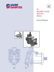
• Bent Axis Motors<br />
• Closed Circuit Axial Piston Pumps<br />
and Motors<br />
• Displays<br />
• Electrohydraulic Power Steering<br />
• Electrohydraulics<br />
• Hydraulic Power Steering<br />
• Integrated Systems<br />
• Joysticks and <strong>Control</strong> <strong>Handle</strong>s<br />
• Microcontrollers and Software<br />
• Open Circuit Axial Piston Pumps<br />
• Orbital Motors<br />
• PLUS+1 GUIDE<br />
• Proportional Valves<br />
• Sensors<br />
• Steering<br />
• Transit Mixer Drives<br />
Members of the Sauer-<strong>Danfoss</strong> Group<br />
Comatrol<br />
www.comatrol.com<br />
Schwarzmüller-Inverter<br />
www.schwarzmueller-inverter.com<br />
Turolla<br />
www.turollaocg.com<br />
Hydro-Gear<br />
www.hydro-gear.com<br />
Sauer-<strong>Danfoss</strong>-Daikin<br />
www.sauer-danfoss-daikin.com<br />
11022667 • Rev EA • Jan 2011<br />
Sauer-<strong>Danfoss</strong> is a global manufacturer and supplier of highquality<br />
hydraulic and electronic components. We specialize in<br />
providing state-of-the-art technology and solutions that excel in<br />
the harsh operating conditions of the mobile off -highway market.<br />
Building on our extensive applications expertise, we work closely<br />
with our customers to ensure exceptional performance for a broad<br />
range of off -highway vehicles.<br />
We can help speed up system development, reduce costs and bring<br />
your vehicles to market faster. Sauer-<strong>Danfoss</strong> – Your Strongest<br />
Partner in Mobile Hydraulics.<br />
Go to www.sauer-danfoss.com for further product information.<br />
Wherever off -highway vehicles are at work, so is Sauer-<strong>Danfoss</strong>.<br />
We off er expert worldwide support for our customers, ensuring<br />
the best possible solutions for outstanding performance. And with<br />
an extensive network of Global Service Partners, we also provide<br />
comprehensive global service for all of our components.<br />
Local address:<br />
Sauer-<strong>Danfoss</strong> (US) Company<br />
2800 East 13th Street<br />
Ames, IA 50010, USA<br />
Phone: +1 515 239 6000<br />
Fax: +1 515 239 6618<br />
Sauer-<strong>Danfoss</strong> GmbH & Co. OHG<br />
Postfach 2460, D-24531 Neumünster<br />
Krokamp 35, D-24539 Neumünster, Germany<br />
Phone: +49 4321 871 0<br />
Fax: +49 4321 871 122<br />
Sauer-<strong>Danfoss</strong> ApS<br />
DK-6430 Nordborg, Denmark<br />
Phone: +45 7488 4444<br />
Fax: +45 7488 4400<br />
Sauer-<strong>Danfoss</strong>-Daikin LTD.<br />
Shin-Osaka TERASAKI 3rd Bldg. 6F<br />
1-5-28 Nishimiyahara, Yodogawa-ku<br />
Osaka 532-0004, Japan<br />
Phone: +81 6 6395 6066<br />
Fax: +81 6 6395 8585<br />
www.sauer-danfoss.com