
Create successful ePaper yourself
Turn your PDF publications into a flip-book with our unique Google optimized e-Paper software.
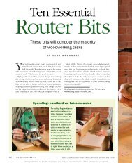
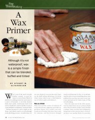
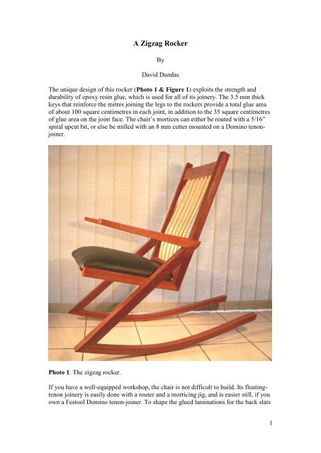
and the rocker, you will need to make formers (Figure 2), either out of solidhardwood or from MDF sheets, face-glued to a thickness of 45 mm.Figure 1. Side view of the chair.2
8411011298858184197185162139119106991001081201361531100600200 mmFigure 2. Formers for the rockers and back slats.ConstructionThe parts for the chair, apart from the seat frame and the laminations for the rockersand back slats, can all be cut from a 45 x 175 x 2200 mm board of primary hardwoodsuch as jarrah, or walnut (Figure 3). The twelve 6.5 mm thick laminations for therockers can be ripped from a 45 x 150 x 1200 mm board of matching hardwood. Thetwelve 4 mm thick laminations for the back slats, and the four mitre keys, can beripped from a 22 x 150 x 1500 board of contrasting hardwood, such as maple.DACBE F G, HFigure 3. Layout of the main chair parts. The letters refer to codes in the cutting list.Making the rockersAfter band-sawing the curve for the rocker former, sand its faces smooth, and linethem with polypropylene packaging tape, to prevent glue from adhering to the former.Rip the laminations for the rockers about 8 mm thick, and plane them to a uniformthickness of 6.5 mm. To glue up the laminations, I used two-part epoxy resin gluewith a gel consistency and a slow hardener. It is essential to use at least two highqualityclamps with parallel jaws, such as Bessey K-body clamps, supplemented bytwo or more heavy-duty bar-clamps, for the glue-up of each rocker. The rockersshould be glued up one at a time, so as to allow plenty of time to spread the epoxy onthe six laminations. As the clamps are successively tightened on the formers, ensurethat the edges of the laminations remain level with one another, using a block of woodto hammer down any lamination that is squeezed upwards relative to its neighbours.After the epoxy is cured, plane away the squeezed-out epoxy, and then plane eachrocker to a uniform width of 40 mm.3
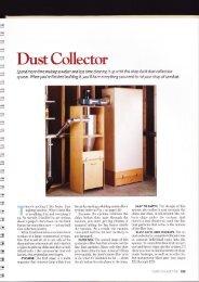
Making the zigzag side-assembliesRip the parts for the legs and arms, and plane and joint them to finish with thedimensions given in the cutting list. With the broader (45mm) face resting on the sawtable, cut 27° mitres on the top ends of the legs and the rear ends of the arms. Cut 30°mitres on the bottom ends of the legs.The easiest way to cut the leg and arm mitres is to use a sliding mitre saw, with a 5°wedge clamped between the workpiece and the fence (Photo 2). Otherwise, you canmake a simple triangular plywood jig (Figure 3), which is clamped to a mitre gaugeon the table saw (Photo 3). The mitres could be also be cut with a back-saw, andplaned to the mark-out lines. The mitres on the rockers need to be planed by handanyway, since there is no way of cutting them accurately with machinery, short ofbuilding an elaborate specialized jig.Photo 2. Cutting a 27° mitre on a sliding mitre saw, using a 5° wedge clampedbetween the workpiece and the fence. You must ensure that the blade will clear theclamp before making the cut.4
Before glueing the arms to the legs, mill 8 x 22 mm mortices 15 mm deep forreinforcing tenons in their mitre faces (Figure 6). Then band-saw the curved top andbottom profiles of the arms, and sand the curves smooth. Glue up the leg/arm mitrejoints, using an 8 x 22 x 29 mm tenon for reinforcement. Sand the completedassemblies, and round over all their edges with a 3 mm radius roundover bit; use a 10mm roundover bit for the bottom edges of the rockers.302198°5427°28°26049°50Figure 6. Joinery details.Making the back-stile/seat side-rail assembliesMill the parts for the seat side-rails and the back stiles to the dimensions given in thecutting list; cut the 49° mitres on their ends, and mill 8 x 22 mortices for thereinforcing tenons 25 mm deep in the mitre faces. Mark out the centre lines for the 8 x22 mortices on their inner faces, taking care to ensure that the assemblies are mirrorimagesof one another (Figure 7). Mill the mortices 20 mm deep. One of the morticesin each pair for the back rails should be milled longer, say 27 mm instead of 22 mm,to allow wiggle room for fitting the 8 x 22 x 40 mm floating tenons.8
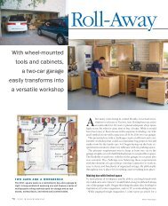
422 49610084°70Figure 9. The seat cross-rails.37940549684°Figure 10. The seat frame.12
Cutting ListPart * Thickness Width Length CommentsA. Legs (2) 40 45 800B. Arms (2) 40 45 525C. Seat side rails (2) 35 40 485D. Back stiles (2) 35 40 735E. Top back rail 40 80 400 Trim ends at 84° tofront face. Bandsaw2060 mm-radiuscurves; curved railfinishes 30 mmthick.F. Bottom back rail 40 65 400 Trim ends at 84° tofront face. Bandsaw2060 mm-radiuscurves; curved railfinishes 30 mmthick.G. Seat cross rail, front 18 55 500 Trim to length; seeFigure 9.H. Seat cross rail, back 18 55 430 Trim to length<strong>Rocker</strong> laminations (12) 6.5 43 1150 Finish 40 mm wideBack slat laminations (12) 4 33 600 Plane to 31 mmwidth after glue-upSeat frame front rail 16 55 496 Trim to length; seeFigure 10.Seat frame back rail 16 55 405 Trim to length.Seat frame side rails 16 55 390 Trim to length.Mitre keys (4) 3.5 75 75Dominoes, or shop-madefloating tenons (2)8 22 48 For back stile/seatside rail joints.Dominoes, or shop-made 8 22 38 For cross rails.floating tenons (12)Dominoes, or shop-madefloating tenons (4)6 20 30 For seat frame.* The code letters for the parts refer to Figure 3.14