DustCollector
DustCollector
DustCollector

You also want an ePaper? Increase the reach of your titles
YUMPU automatically turns print PDFs into web optimized ePapers that Google loves.
-<br />
-<br />
-i<br />
-<br />
-l<br />
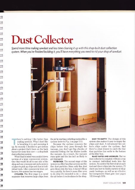
<strong>DustCollector</strong><br />
Spend more time making sawdust and less time cleaning it up with this shop-built dust collection<br />
system. When you're finished buitding it, you'll have everythíng you need to rid your shop of sawdust.<br />
-<br />
=<br />
-<br />
-<br />
=<br />
-<br />
=<br />
-t<br />
T<br />
-<br />
-<br />
.i<br />
=<br />
.r<br />
{<br />
-<br />
-<br />
-<br />
.I<br />
:'::i::::,*.here's nothing I like better than<br />
;;j making sawdust. \Vhat I don't like<br />
't is breathing it in and sweeping it<br />
up. So recently I decided to get serious<br />
about a project that's been on the back<br />
burner for some time now<br />
- a shopbuilt<br />
dust collection system.<br />
IÁrtrat I had in mind was a scaled-down<br />
version of a large commercial system.<br />
One that would sit off to one side of the<br />
shop and use a vacuum unit and a system<br />
of pipes to pick up chips and dust at individual<br />
tools. Like commercial dust collectors,<br />
this system has hvo stages.<br />
cYcLoNE. The Íirst stage is a metal<br />
separator that removes large chips from<br />
the air by starting awhirling motion like a<br />
cyclone (referto Fig.1 onpage 111).<br />
Because the cyclone removes the<br />
chips before they pass through the<br />
vacuum, you don't get big chunks of<br />
material hitting the fan blades inside<br />
the vacuum. As a result, the vacuum<br />
runs quiet and the fan isn't as likely to<br />
get damaged.<br />
FTLTER Box. The second stage of this<br />
system is a filter box that screens out the<br />
fine dust particles. Since only fine dust<br />
gets blown into the box, it doesn't fill up<br />
very quickly. So there's more filter area<br />
to do what it's intended to do<br />
- clean<br />
the air before it recirculates in the shop.<br />
EAsY To EMPTY. The design of this<br />
system also makes it easy to empty the<br />
chips and dust. A roll-around bin collects<br />
chips under the cyclone. And<br />
there's a dust drawer to catch the fine<br />
dust particles that settle to the bottom<br />
of the filter box.<br />
BLAST GATES AND HOOKUPS. But no<br />
dust collector is complete without a way<br />
to connect individual tools into the<br />
system. To control the flow of air at each<br />
tool and direct chips into the system, I'11<br />
show you how to build a variety of shop<br />
made hookups, as well as an effective<br />
but inexpensive blast gate (see pages<br />
122 through 125).<br />
ï<br />
t!ilg51"{*Li.{eT*R 109
I-<br />
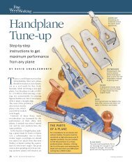
EXPLODED VIEW<br />
OVERALL DIMENSIONS:<br />
21Wx203/aDx69H<br />
(WITHOUTVACUUM)<br />
I-<br />
+<br />
t-<br />
!-<br />
L<br />
L-<br />
iÉ-<br />
ir-<br />
.-@<br />
TOP CONE<br />
BOTTOM<br />
CONE SUPPORT<br />
o<br />
!-<br />
#8 x 2"<br />
Fh WOODSCREWS<br />
3lz" x \lq"<br />
DRAW CATCH<br />
672" DRAWER<br />
PULL<br />
tf--<br />
+<br />
r--<br />
FRONT/BACK<br />
o<br />
I-<br />
!L<br />
o<br />
BIN BOTTOM<br />
rI-<br />
+-<br />
2" SWIVEL CASTER<br />
rI-<br />
Ë.-<br />
!L<br />
CUTTING DIAGRAM<br />
3/r' PLYWOOD - 48 x 96<br />
3/a" PLYWOOD - 48 x 96<br />
=-<br />
Ja-<br />
ir-<br />
!L<br />
+<br />
ALSO REQUIRED:<br />
ONE 24' x 48' SHEET OF<br />
78" HARDBOARD FOR SIDES AND<br />
TWO 7q"-THICK HARDWOOD<br />
PTECES (2" WtDE 20' LONG.)<br />
=<br />
=<br />
ir-<br />
=<br />
=
:<br />
CONE (l\,1ateria s for cyclone only Materia s<br />
ior tr ter Box on page 1 1 B.)<br />
3/tpy - 2A x44<br />
A Lo\,\,er Sides (2)<br />
B Top Cone Spprt (1 ) j/ipy - 20 x20<br />
C Btm Cone Spprt {1)% ply - 20 x20<br />
D Stretchers(2) 3/:p|y-6x19'/t<br />
. CYLINDER<br />
I E Btm. Cyl Sppt (1) 3/+ply-20x20<br />
I F CylinderTop(1) 3/qply -20x20rqh<br />
G Upper Sides (2) 3/t ply - 20 x 24<br />
H Vacuum Platform (1)% ply - 20 x20<br />
CHIP BIN<br />
I FronVBack (2)<br />
J Bin Bottom (1)<br />
K Sides (2)<br />
L Srde Raiis (2) 3/t x 2 - 20<br />
M Stop(1) '/tply-6x21<br />
3/a ply - 171/2 x223lg<br />
3/aply - 171/2y181/2<br />
r/s<br />
hdbd - 20 x223/s<br />
The heart of the Dust Coliector is a<br />
shop-built cyclone that separates the<br />
HARDWARE SUPPLIES<br />
(16) No Bx1 Fi'\1.'cccsc.e\.is<br />
(6) No B x": /: 1r,.1.'cccs.'Ê'.'.'s<br />
(68) \o Bx2 ='.'.J:Ji1 .:..)<br />
(30' No Bx i- ..--:c:: -..:<br />
(1 b.) 1 /. " tr:rg-sr-::r< .a s<br />
( 1 3) Pop r vets<br />
(10') 20 -wide galvan zeci sree: :r's:a<br />
,7) /; xl/: êt\\er- e'S.'.C--q<br />
() 4' x 24' metal DiDe<br />
(1) 6' x 24" metal prpe<br />
(2) 2" swivel casters<br />
(2) 2" fixed casters<br />
(2) 61/z' drawer pul s<br />
(4) 31h' x 1rla' drawcatches<br />
(1) Tube of silicone caulk<br />
(1) Roll of metal forl tape<br />
large chips out of the incoming air. The<br />
cyclone is designecl to work together<br />
with a vacuunl that draws air into the<br />
systern (Fiu. 1). With the cyclone<br />
ren.roving the chips before they pass<br />
through the vacuum, you'll extend the<br />
life of sorne of the moving parts (like<br />
the fan blades) inside the vacuum.<br />
Anotlier benefit is noise reduction<br />
-<br />
the vacuuur s.ill run a lot quieter.<br />
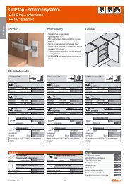
VACUUM. There are a couple of<br />
opiions ior the vacuum. You can hook<br />
an existing portable clust collector up to<br />
the c1-cl,rne (see the photo belorv). Or<br />
]'ou can llu]- a stancl-alone vacuutr to<br />
nrorlnt on top rIi 1. i r. I bought a<br />
vacui-lur that cirari's 5t tt t cubic lèet of air<br />
per luintlte. Se'e page 12t; iet- sources.<br />
CYCLONE. Regardless of ihe r-acuum.<br />
rvirat causes the chips io seitle out is the<br />
shape of the c1-c1one. Tiiis c1'clone- is<br />
built up from two shapes<br />
- a c1'lindcr<br />
and a cone. Both shapes are itrrmcd<br />
from sheet metal. I usecl 20"-ii'ide galr'anized<br />
steel flashing.<br />
Safety Note: Just to be on the saie<br />
side, I always wear heaq,--du6- leather<br />
gloves when cutting metal pipe or sheet<br />
metal with tin snips. A sharp edge h'ont<br />
the cut off pieces could easily cause<br />
serious injury.<br />
The cylinder and cone are held in<br />
place by two plS,wood frames that are<br />
stacked on top of each other lilie<br />
building blocks (I'ig. 1). The botton-r<br />
frarne houses the cone and a bin for the<br />
chips; the top frame supports the<br />
cylinder and the vacuun.<br />
-<br />
.-|<br />
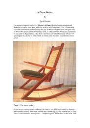
If you already have a dust collector, the<br />
cyclone can make it more efficient by<br />
removing the bulk of the sawdust<br />
before it gets to the vacuum.<br />
-l<br />
lll
B-<br />
E--<br />
F=<br />
CUT DADO<br />
3Z'PLYWOOD<br />
CONE PIECES MADE<br />
FROM TIGHT{AUGE<br />
SHEET METAL<br />
a. cur RABBET To<br />
. l\\\.\\\\\<br />
l.i'{'{.{'{'.Mlffi++rffiiil'<br />
-<br />
' Lzz
-Dr<br />
=<br />
=<br />
-E<br />
t<br />
|<br />
'f<br />
--<br />
T<br />
-<br />
...F<br />
=<br />
-<br />
-<br />
=<br />
-<br />
T"<br />
='<br />
..<br />
-<br />
..T<br />
-r<br />
=<br />
--r<br />
-<br />
-<br />
-<br />
:<br />
-<br />
(For more information on how to<br />
use pop rivets, see the Shop Info below.)<br />
DRILL HOLES. With the rivets in hand,<br />
the next step is to drill holes that match<br />
the diarneter of the rivets. I found it easiest<br />
to lay the pieces out flat so there's a<br />
1rr overlap down the center seam<br />
(Fig. 5a). The only problem is keeping<br />
the sheet metal pieces from moving<br />
rvhile you driil the holes.<br />
To solve this, I aligned the top and<br />
bottom edges so they're flush, and then<br />
used masking tape to temporariiy hold<br />
the seams together (Fig. 5). Then it's<br />
just a matter of drilling a series of holes<br />
and installing the rivets.<br />
Note: I used a scrap 2x4 as a backing<br />
board when driiling the holes.<br />
FORM CONE. Now you're ready to put<br />
the cone in place. At this point. it's no<br />
big deal if it's not a perfect cone. Just as<br />
long as it's rolled up tight enough to slip<br />
the metal down through the top and<br />
bottom cone supports.<br />
The thing to keep in n-rind here is<br />
where the seam that's rroÍ riveted<br />
together is located. You'll rvant to<br />
ensure that it faces an open end of the<br />
frame (instead of the side). So I centered<br />
the riveted seam on an open end<br />
of the cone supports (Fíg. (;).<br />
Although this roughly positions the<br />
sheet metal, you'll still need to slide it<br />
up or down a bit to geL the top and<br />
bottom edges flush with the cone supports.<br />
The trick is to keep both edges<br />
aligned while you attach the sheet metal<br />
to the supports.<br />
ATTACH METAL. What worked best<br />
for me was to tackie a small section at a<br />
time. So I started at the riveted seam<br />
and worked in both directions, nailing<br />
the top and bottom edges in place<br />
as I worked myway around (Fí9. 6a).<br />
Note: I used hardened ring-shank<br />
nails to punch through the metal.<br />
RIVET SEAM. After nailing the cone all<br />
the way around, the last seam can be<br />
riveted. To prevent the metal frorn<br />
crumpling when drilling the holes for<br />
these rivets, I clamped a short section<br />
of board (on edge) over the inside of<br />
the seam (Fig.7).<br />
SEAI SEAMS. Now al1 that's needed to<br />
complete the cone is to seal the seams.<br />
To do this, I first covered each seam<br />
with a short strip of metal foil tape. ffou<br />
could also use duct tape.) Then simply<br />
apply a thin bead of silicone cauik<br />
where the metal cone meets the plywood<br />
supports (Fig.8).<br />
z<br />
STRETCHERS. Finally, to keep the<br />
frame from racking, I added two<br />
stretchers (D). These stretchers<br />
are just pieces of %rr-thick plywood<br />
that are cut to fit between the sides<br />
and screwed in place ( F ig. 8).<br />
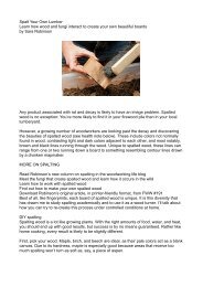
SrePilNF@<br />
op rivets are a quick and easy way<br />
to fasten two pieces of sheet<br />
metal together securely. After<br />
drilling a hole to fit the rivet, a special<br />
riveting tool is used to compress the<br />
rivet (bottom photo).<br />
What makes this work is a pin<br />
that passes through a hole in the rivet<br />
(top photo). The long end of this pin<br />
is gripped tightly in the gun. The<br />
opposite end has a mushroom-like<br />
"ball" that's larger than the hole<br />
in the rivet.<br />
By squeezing the gun handles, the<br />
pin pulls back and draws the ball<br />
against the end of the rivet. This flares<br />
the end of the rivet. Once the rivet is<br />
permanently set, the pin "pops" off.<br />
SECOND:<br />
NAIL<br />
TOP AND<br />
BOTTOM<br />
EDGES<br />
(SEE DETALL a)<br />
FIRST<br />
CLAMP EOARD ACROSS<br />
INSIDE OF sEAM<br />
TO DRILL HOLES -<br />
/z'<br />
-,^<br />
À-<br />
#8x2" Fh<br />
WOODSCRËW<br />
\<br />
a'<br />
o<br />
-<br />
S'AL BOTiI SEA\,15 \'J.ïr<br />
METAL FOiL -ÁPE<br />
17q" R|NG-sHANK NAIL<br />
APPLY<br />
StLtcoNE<br />
CAULK WHERE<br />
CONE MEETS<br />
l<br />
o<br />
STRETCHER<br />
Klvets<br />
.-1<br />
.-
l{<br />
lr-<br />
I 6'/4<br />
I<br />
CYLINDER PAÏTERN<br />
(ONE PIECE)<br />
NOTE:<br />
CYLINDER 15<br />
MADE FROM<br />
SHEET METAL<br />
DRAW CENTERLINE<br />
ON CYLINDER TO<br />
HELP LAY OUT INLET<br />
AND FOR HELP<br />
POSITIONING CYLINDER LATER<br />
After completing the cone, the next step<br />
is to add the cylinder above it. Here<br />
again, the cylinder is made from a piece<br />
of light-gauge sheet metal that's supported<br />
by a plyrvood frame.<br />
FoRMs. As with the cone. I used two<br />
tÁ"-thick ply.lvood pieces as a "form" for<br />
the cylinder. Once they're cut to shape,<br />
you'll be able to attach the sheet metal<br />
to the edges of the plywood with nails.<br />
1b match the opening in the top of the<br />
cone, the bottom cylinder support (E)<br />
has a 16'r-dia. hole cut in it (Fígs. 10<br />
atrd 11). After you've cut the bottom<br />
cylinder support, be sure to save the<br />
round disk that's removed. It's the perfect<br />
size for the cylincler top (F).<br />
To cut out the cylinder top, simply<br />
drill a series of small holes along the<br />
circle as an entry point for the jig saw<br />
blade (Fíg.-zirr). While you're at it,<br />
you'll also want to cut a 6rr-dia. opening<br />
for an outlet pipe into the vacuum<br />
(Fig. 11). Once again, a jig saw makes<br />
quick work of this.<br />
Note: Be sure to set your jig saw<br />
blade back to 90" before making either<br />
ofthese cuts.<br />
CYLINDER. Now work can begin on<br />
the cylinder. Basically, it's just a rectangular<br />
piece of sheet n-retal rolled up to<br />
form the cylinder. The only unusual<br />
thing is a teardrop-shapecl opening that<br />
will be cut out near the top edge (Fí9. 9).<br />
The reason for this opening is<br />
simple. Once the rnetal is formed into a<br />
cylinder, it allows an inlet pipe to fit<br />
tightly inside. The thing to be aware oÍ<br />
is the tip of the opening is locatecl on a<br />
line that's centered on the length of the<br />
metal. Later, this provicles a reference<br />
for positioning the cylinder.<br />
FORM CYLINDER. After cutting the<br />
metal to shape, you can forrn the<br />
cylincler. I started by wrapping the<br />
metal around the top (F). Then I nailed<br />
it in place as I worked my way around<br />
(Fig. 12). Just be sure that the metal<br />
remains straight as you go.<br />
Note: Once again, I used the same<br />
sb'le of ring-shanked nails here that I<br />
used earlier on the cone assembly.<br />
E<br />
E<br />
E-<br />
rr-<br />
Irlrla-<br />
Ér-<br />
}|<br />
rr-<br />
lr-<br />
Ir-<br />
1..-<br />
h<br />
lr-<br />
11<br />
-s<br />
I<br />
:ur 4'-DrA.<br />
\<br />
I a<br />
HOLE FOR<br />
INLET PIPE<br />
114',.':r'.t',.,r'l1i<br />
VACUUM<br />
PLATFORM<br />
OF SMALL HOLES<br />
TO INSERT BLADE<br />
] o'-o,o<br />
I<br />
|NLET P|PE<br />
CYLINDER<br />
NOTE:<br />
__.<br />
CUT 7r'-DEEP RABBET TO<br />
Frr /r,,_THrcK plywooD \ -20 DRILL SERIES<br />
FIRSÏ NAIL METAL<br />
AROUND CYLINDER TOP<br />
SO TOP EDGE 15 FLUSH<br />
BOTTOM<br />
SUPPORT<br />
lr-<br />
ll-<br />
}|-<br />
Èr-<br />
Fr-<br />
1..<br />
}r<br />
!ala<br />
E<br />
F,<br />
F<br />
F
-!<br />
-<br />
-<br />
a<br />
-<br />
-<br />
-<br />
=<br />
=<br />
.-<br />
-<br />
=<br />
-<br />
-<br />
-<br />
€<br />
-<br />
Now the sheet metal cylinder can be<br />
fit in the opening in the bottom support<br />
(E). This is just a matter of matching<br />
the centerline that was drawn earlier<br />
on the cylinder with a line centered on<br />
the support, then nailing everything<br />
in place (Fit/. 12).<br />
RIVET SEAM. The next step is to rivet<br />
the seam. As with the cone, I used a<br />
scrap piece as a backing board to<br />
support the metal when drilling the<br />
holes. Then, after installing the rivets,<br />
seal the seam with a strip of metal<br />
foil tape (Fig. 12cL).<br />
ToP FRAME. At this point, the top<br />
frame can be built around the cylinder.<br />
This frame consists of two upper sides<br />
(G) and a vacuum platform (H)<br />
(FiU. lO). Each side is rabbeted at the<br />
top and bottom ends to accept the<br />
vacuum platform and the bottom<br />
cylinder support.<br />
To allow the inlet pipe to pass through<br />
the frame, you'll need to cut a 4rldia. hole<br />
in one side piece of the frame. Also,<br />
before screwing the frame together. go<br />
ahead and cut a 6rr-dia. hole in the<br />
vacuum platform. This hole is for an<br />
outlet pipe that's aclded later ( Fí9. 1í)).<br />
INLET. Aíter assembling the frame, I<br />
installed the inlet pipe. This is just a<br />
4rldia. metal pipe that passes through<br />
the hole in the side ancl into the<br />
cylinder. To reduce the arnount of pipe<br />
that sticks inside, you'Il want to trirn the<br />
end off to match the opening in the<br />
cylinder (Fit/. l.l). An easy way to do<br />
this is to trace the shape of the opening<br />
onto the pipe with a permanent marker<br />
NAIL OUTLET ,I' PIPE ABOVE<br />
VACUUM PLATFORM<br />
-<br />
i<br />
0000000<br />
RIVFT RIVET TIP OF PIPF PIPE<br />
TO CYLINDER<br />
NOTE: INLET PIPE<br />
EXTENDS 7:' INTO CYLINDER<br />
(Fig. 1.]). Then, after trirnning the pipe<br />
with a pair of tin snips, sneak the end<br />
just past the cylinder wall and rivet the<br />
tip in place (Fígs. 1.)ct utrd 1.lb).<br />
Next, you'll need to cut off the<br />
crirnped end of the inlet pipe (Fig. 1.1).<br />
This rvay I's11'll end up rvith an uncrimpecl<br />
end for an adustable elborv addecl later.<br />
And it allorvs the air to flori- suroothll'<br />
through the pipe (r'efer to the photo on<br />
page 120 and Fi(t. Jj on page 121).<br />
OUTLET. In aclclition to the inlet.<br />
there's a 6"-dia. outlet pipe that helps<br />
direct the fine dust into the vacuuln.<br />
The idea here is to locate the bottom<br />
end of this pipe so the vacuum won't<br />
suck up large wood chips that are<br />
coming into the cyclone.<br />
To do this, I slipped a 24r' length of<br />
pipe through the holes in the cylinder<br />
a. cAULK LocATtoNs<br />
SLIDE PIPË INTO<br />
CYLINDER AND TRACE<br />
AROUND INLET WITH<br />
top and the vacuurn platform ( F iq. 1 D .<br />
The top end of the pipe is nailecl in place<br />
so it extends 1" above the vacuuur platform.<br />
This way, the bottom end extends<br />
far enough into the cylinder so it carries<br />
off only the fine dust particles.<br />
CAUIK. Once the outlet is installed,<br />
tlre cylinder can be sealed (Fig. 1.!u).<br />
Ercept tbr one place, I caulked on the<br />
orrt;itlr, of the metal (orpipe). including<br />
arouncl the outlet and inlet pipes ancl<br />
around the base of the c1'linder. But<br />
rvhere the c1'lincler top meets the metal,<br />
you'll need to apply a beacl of caulk ou<br />
ïhe íttsirle (Fíq. f .iu ).<br />
STACK FRAMES. Norv all that's left is to<br />
screw the top and bottom frames<br />
together using No. 8 x 1%" flathead<br />
woodscrews, so the flames are flush all<br />
the way around ( F ig. l:t ).<br />
0 0 0lo<br />
'l<br />
0<br />
+<br />
I<br />
i<br />
)<br />
--]<br />
AROUND INLËT<br />
lL-<br />
I<br />
I<br />
;i lt5
One handy feature of this cyclone is a<br />
roll-around chip bin. I wanted something<br />
that I wouldn't have to empty<br />
every day, so I made sure the bin was<br />
extra large. It measures almost 24tt tall<br />
and it's 171/zttwide and 20rr deep.<br />
A bin this large could get heaqz<br />
though, so I added casters and handles<br />
to make it easy to empty. \Áhen the bin<br />
fills up with chips, all you have to do is<br />
ro11 it out from under the cyclone and<br />
empff it in the trash.<br />
BlN. There's nothing complicated<br />
about building the bin. The front/back<br />
pieces (l) are made from 3Árr-thick plywood,<br />
and are glued and screwed to the<br />
bottom (J) using simple butt joints<br />
(Fi.g. 16). And to rnake the chip bin as<br />
lightweight as possible, I decided to<br />
make the sides (IO from r/srr-thick hardboard.<br />
Here again, they're just glued<br />
and screwed in place.<br />
Note: I used tempered hardboard<br />
for the sides. Tempered hardboard is<br />
smooth on both sides. This allows the<br />
sawdust and wood chips to slide off<br />
whenever the bin needs emptying.<br />
SIDE RAILS. Next, to help stiÍíen the<br />
1/s"-thick sides, I attached a pair of<br />
hardwood side rails (L) with glue and<br />
screws. These rails also act as<br />
"bumpers," protecting the cart when<br />
you roll it in and out from underneath<br />
the cyclone.<br />
CASTERS. After attaching the rails, I<br />
added a set of four 2rr casters. 1b help<br />
steer the bin, two swivel casters are<br />
screwed in place along the front edge,<br />
and a pair offixed casters along the back.<br />
3/s" x 11/a"<br />
FEIT<br />
WEATHER-<br />
STRIPPING<br />
g-ql<br />
a'<br />
iÍAPLE--'/<br />
WEATHERSTRIPPING<br />
UNDER BOTTOM<br />
CONE SUPPORT<br />
-u<br />
STOP<br />
(6" x 21")<br />
-t<br />
SIDE RAIL<br />
(3/a"-THICK HARDWOOD-<br />
2" x 20")<br />
sToP. Now to help keep the bin centered<br />
under the cyclone, I screwed a<br />
stop (M) to the back of the lower sides<br />
(Fí9. 1t;). The stop is made from plywood.<br />
With it in place, you just push the<br />
chip bin in until it hits against the stop.<br />
But just rolling the bin under the<br />
cyclone isn't enough. The key is to seal<br />
it so chips don't blow out. To do this, I<br />
used a lwo-part system.<br />
GASKET. The first part is a "gasket"<br />
made from pieces of felt weatherstrippins<br />
(tríg. 1i). éJter cutting strips of<br />
this felt to fit under the bottom cone<br />
support, they're stapled in place.<br />
But to produce a goocl seal, the bin<br />
needs to draw up tight against the felt.<br />
CLAMP BIN IN<br />
PLACE TO<br />
LOCATE DRAW<br />
CAÏCHES -<br />
0<br />
--2<br />
(4)<br />
LOWËR<br />
NOTE: ALL PARTS EXCEPT SIDES AND<br />
SIDE RAILS MADE FROM<br />
3/q"-THICK PLYWOOD<br />
6<br />
stDE r'' o<br />
FRONT<br />
,ë'<br />
That's where the second part of the<br />
system comes in.<br />
DRAW CATCHES. To raise the bin off<br />
the floor, there's a pair of draw catches<br />
on the front and back of the cyclone<br />
(Fig. 18). When you snap the catches<br />
shut, the bin compresses the felt and<br />
creates an airtight seal. To locate the<br />
catches, I clamped the bin in the<br />
"closed" position and screwed a pair of<br />
catches to both the front and back<br />
pieces (Flgs. 18 ttttcl 18cL).<br />
DRAWER PULLS. Finally, to make it<br />
easy to lift and empfiz the bin, I screwed<br />
on a couple of hear,y-duty drawer pulls,<br />
placing one on the front and another on<br />
the back of the bin.<br />
a)l<br />
;l tl<br />
uJái'.^,Ld I<br />
srnercHER@ll<br />
scnew srnrre I<br />
PLATE To<br />
I<br />
FRoNT/BAcK )<br />
PIECES.'.-<br />
-----'<br />
2- CASTER<br />
(1 PArR F|XED)<br />
1 PAIR SWIVEL)<br />
)\'_<br />
.1,<br />
\l<br />
\l/<br />
Y<br />
3lz" x 1la" DRAW CATCH<br />
(SEE DETAIL a)<br />
NOTE: INSTALL DRAW CATCHES<br />
AND PULLS ON BOTH 5IDE5<br />
CONË<br />
SUPPORï<br />
\(\.<br />
Ftts:<<br />
WEAïTtËR-<br />
'ÍR}PPIN€<br />
.l ,<br />
i<br />
€<br />
=<br />
=<br />
=<br />
=<br />
=<br />
=<br />
F-<br />
--<br />
E_<br />
É-<br />
F.<br />
-<br />
t:--<br />
--<br />
tr-<br />
t--<br />
ta-<br />
F-<br />
tr.-<br />
tr.-<br />
,--<br />
=<br />
=<br />
=<br />
=<br />
=<br />
=<br />
=<br />
=<br />
ll6 .::i r::,,i".11r..,1 I i'irr.<br />
= r-
-=<br />
-'.-<br />
.-<br />
--<br />
+<br />
:<br />
=<br />
-<br />
=<br />
=<br />
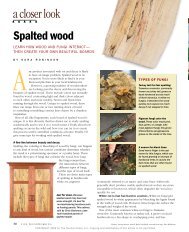
DESI@NERTS NOryEB@@K<br />
To ensure the Dust Collector runs effíciently, you'll need to check ít regularly. Adding a wíndow will help.<br />
The Dust Collector won't work as weli<br />
when the chip bin is over flowing with<br />
saw dust and chips. So to make it easy to<br />
check it, you can add a small "window."<br />
The window lets you peek into the bin<br />
without having to unlatch the draw<br />
catches and pull it out.<br />
Start by cutting a srnall hole on the<br />
outside of the bin (see drawing) .<br />
Then cover the hole with a thin piece<br />
of clear acrylic plastic using some<br />
tÁ'rlong woodscrews.<br />
Note: Before screwing the clear<br />
acyrlic plastic in place, it's a good idea<br />
to apply a bead of caulk to stop any air<br />
leaks (see drawing).<br />
Now when you want to check the<br />
chip level inside the chip bin collector,<br />
all you have to do is look through the<br />
acrylic plastic window.<br />
-..-<br />
--<br />
--<br />
..-<br />
---|<br />
--<br />
-a<br />
-a<br />
--<br />
--r<br />
-ï<br />
-r<br />
At this point, all that's left to complete<br />
the cyclone is to connect the vacuum<br />
and the motor.<br />
If you're using a portable dust collector,<br />
run a length of flexible hose from<br />
the inlet to the outlet pipe from the<br />
cyclone (refer to the photo on page 1 I 1) .<br />
Note: You ma,v also need a reducer<br />
and a hose clamp to attach the hose.<br />
PLATFORM MOUNT. But AnOthCr,<br />
more compact setup is to mount a<br />
vacuum unit on top of the vacuum platform.<br />
Here, the inlet of the vacuum fits<br />
loosely inside the outlet pipe from the<br />
cyclone. Depending on horv well the<br />
inlet fits, you ma]' neecl to modiÍy the<br />
connection to keep the vacuuur from<br />
sucking in outside air. So i'ou'Il need to<br />
make an airtight seal behveen the inlet<br />
and the outlet(Fig. l!)).<br />
DoUGHNUT. What rvorked rvell for<br />
me was to cut a "doughnut" tiorn a piece<br />
of l"Árr-thick soft foarn (like the kincl<br />
available at most fabric stores). Cut the<br />
doughnut to fit around the outlet pipe.<br />
This way, when you mount the vacuum,<br />
the weight of the vacuulrr squeezes<br />
down the foam and forms a gasket<br />
around the outlet.<br />
The trick is to cornpress the foam<br />
without having the vacuum "bottom<br />
out" on the pipe. This requires raising<br />
the vacuum off the platform. To do this,<br />
I r-rsed a stack of nylon spacers<br />
and some rubber washers at each<br />
mounting point (Fí9. 19ct).<br />
Depending on the vacuum you use,<br />
the location of these mounting points<br />
(and the fasteners) will vary. The<br />
vacurlm I used had threaded holes in the<br />
housing, so I attached it with hex bolts.<br />
0<br />
!<br />
i<br />
But you may need to drill holes and use<br />
self-tapping screws. Either way, siipping<br />
on a lock washer keeps the bolts (or<br />
screws) frorn vibrating loose ( F í fl. I ll ).<br />
ELECTRICAL HOOKUP. One final note.<br />
You can plug the vacuulrr into an outlet<br />
with a switch and receptable, and use<br />
the switch to turn it on and off. Or,<br />
simply plug and unplug the unit into a<br />
wall outlet to turn it on and off.<br />
CONNECTS TO FILTER BOX<br />
s--- (SEE PAGE 118)<br />
-<br />
l-<br />
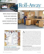
EXPLODED VIEW<br />
OVERALL DIMENSIONS:<br />
32Wx20Dx84H<br />
SCREEN<br />
I\4OLDING<br />
/ffi<br />
\\o<br />
ToP<br />
#8 x 2"Fh<br />
WOODSCREW<br />
Most dust collection systelns rely on<br />
fabric bags to filter out fine dust particles.<br />
But there are a couple of problems<br />
with these. First, they're expensive.<br />
And second, I've found that most bags<br />
are too small for the system. \\4ren it's<br />
turned on, the filter bag quickly inflates,<br />
producing a cloud of fine dust that settles<br />
over the entire shop.<br />
To solve both these problems, I<br />
didn't use a bag. Instead, I built a large<br />
filter box (see photo at left). It's just a<br />
wood frame wrapped with inexpensive<br />
fabric. Since the fabric is stretchecl<br />
=<br />
l-<br />
I.<br />
I_<br />
r,-<br />
Fa-<br />
I-.-<br />
É<br />
IL<br />
UPRIGHT<br />
SCRE EN<br />
MOLDING<br />
SUPPORT<br />
FRAME<br />
A Uprights (4) 3/tx 11/z - 831/a<br />
B Bottorn Plates (2) 3h ply - 123/t x 17<br />
C Rails (6) 3/qx11/t- 17<br />
D lnlet Plate (1 )<br />
3/rply - 191lsx 17<br />
E Stretchers(10)<br />
F Top(1)<br />
3hx11/z-3A1/z<br />
3/tply-20x32<br />
G Supports (2) 3/tply - 53/tx301/z<br />
H Side Pieces (2) 3/a<br />
x 11/z - 301/z<br />
I End P eces (2) 3/!,x 11/z - 151/z<br />
rrl-<br />
É<br />
TL<br />
IL<br />
l---<br />
DUST DRAWER<br />
J FronVBack(2) %ply-6x30<br />
K DrawerSides(2) 3/aply - 6x19<br />
L Drawer Bottom (1) r/a hdbd - 19 x29<br />
}È<br />
I.<br />
BOTTOM \<br />
PLATE<br />
'-@ -<br />
CUTTING DIAGRAM<br />
%'BIRCH PLYWOOD - 48 x 96<br />
END<br />
PI ECE<br />
a)<br />
FRONT/BACK<br />
HARDWARE SUPPLIES<br />
(26') Screen molding<br />
(66) No Bx2" Fhwoodscrews<br />
(28) No. 8 x 3' Fh woodscrews<br />
(4) 31b' x 1 r/"r ' draw catches w/ screws<br />
(9'l 3/ta' x 1<br />
r/+" felt weatherstrlpping (1lb )<br />
(21 6t1r" drawer pulls w/ screws<br />
(3 yds) 10 oz. cotïon duck fabric - 72" wtde<br />
(2 oz pkg ) #1B x 1 " wrre brads<br />
(1) 5 '-dia metal duct for inlet<br />
(1 pkg ) %" staples<br />
iL<br />
L<br />
a-<br />
t*-<br />
1-<br />
-<br />
L<br />
1x12 (,! x 11',':) - 96 PINE (7.7 Bd. Ft.)<br />
1x8 (3/a xTln) - 96 PINE (5 Bd. Ft.)<br />
il8<br />
l-<br />
=<br />
-<br />
Í<br />
í<br />
a<br />
-
f,<br />
t<br />
!<br />
a:r:t : C( )llalJjSe<br />
.,.rr:rcti (lit -<br />
FILTER MATERIAL. In dcsigning the<br />
-:' - .-.-. :::r rl:si thilg I had to figure<br />
. ''.'-:s ',', lr:.1 i,r r,1se i(lr 1àbric. ] founcl<br />
,.: .','r-::: I :r.ec1eci at a local ïabric store<br />
- - z. r,,.., )n due l; rlrllrie .<br />
SIZE. Thc onl1' other thing to decicle<br />
,,'-,. :rr,i',' iriq to lnalie the lrane. The<br />
..=::iri '\-,'as eas]-. I sized the frame to Ïit<br />
,... ,,,.'ic1th of the ïabric (72rr). All thatwas<br />
---- i','as to iigure out how much filter<br />
:r:clt ] needed.<br />
Ii the tllter area is too small. the dust<br />
-rls forced right through the fabric like<br />
lr cioggecl bag on a vacuum cleaner. So<br />
iiirer taiiing into account the size of my<br />
\'.lcuum (500 CFN,I), I came up with the<br />
clesign shorvn in the Exploded View on<br />
the previous page.<br />
Sc,<br />