DustCollector
DustCollector
DustCollector

Create successful ePaper yourself
Turn your PDF publications into a flip-book with our unique Google optimized e-Paper software.
l{<br />
lr-<br />
I 6'/4<br />
I<br />
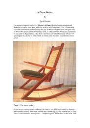
CYLINDER PAÏTERN<br />
(ONE PIECE)<br />
NOTE:<br />
CYLINDER 15<br />
MADE FROM<br />
SHEET METAL<br />
DRAW CENTERLINE<br />
ON CYLINDER TO<br />
HELP LAY OUT INLET<br />
AND FOR HELP<br />
POSITIONING CYLINDER LATER<br />
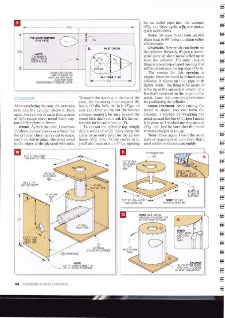
After completing the cone, the next step<br />
is to add the cylinder above it. Here<br />
again, the cylinder is made from a piece<br />
of light-gauge sheet metal that's supported<br />
by a plyrvood frame.<br />
FoRMs. As with the cone. I used two<br />
tÁ"-thick ply.lvood pieces as a "form" for<br />
the cylinder. Once they're cut to shape,<br />
you'll be able to attach the sheet metal<br />
to the edges of the plywood with nails.<br />
1b match the opening in the top of the<br />
cone, the bottom cylinder support (E)<br />
has a 16'r-dia. hole cut in it (Fígs. 10<br />
atrd 11). After you've cut the bottom<br />
cylinder support, be sure to save the<br />
round disk that's removed. It's the perfect<br />
size for the cylincler top (F).<br />
To cut out the cylinder top, simply<br />
drill a series of small holes along the<br />
circle as an entry point for the jig saw<br />
blade (Fíg.-zirr). While you're at it,<br />
you'll also want to cut a 6rr-dia. opening<br />
for an outlet pipe into the vacuum<br />
(Fig. 11). Once again, a jig saw makes<br />
quick work of this.<br />
Note: Be sure to set your jig saw<br />
blade back to 90" before making either<br />
ofthese cuts.<br />
CYLINDER. Now work can begin on<br />
the cylinder. Basically, it's just a rectangular<br />
piece of sheet n-retal rolled up to<br />
form the cylinder. The only unusual<br />
thing is a teardrop-shapecl opening that<br />
will be cut out near the top edge (Fí9. 9).<br />
The reason for this opening is<br />
simple. Once the rnetal is formed into a<br />
cylinder, it allows an inlet pipe to fit<br />
tightly inside. The thing to be aware oÍ<br />
is the tip of the opening is locatecl on a<br />
line that's centered on the length of the<br />
metal. Later, this provicles a reference<br />
for positioning the cylinder.<br />
FORM CYLINDER. After cutting the<br />
metal to shape, you can forrn the<br />
cylincler. I started by wrapping the<br />
metal around the top (F). Then I nailed<br />
it in place as I worked my way around<br />
(Fig. 12). Just be sure that the metal<br />
remains straight as you go.<br />
Note: Once again, I used the same<br />
sb'le of ring-shanked nails here that I<br />
used earlier on the cone assembly.<br />
E<br />
E<br />
E-<br />
rr-<br />
Irlrla-<br />
Ér-<br />
}|<br />
rr-<br />
lr-<br />
Ir-<br />
1..-<br />
h<br />
lr-<br />
11<br />
-s<br />
I<br />
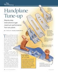
:ur 4'-DrA.<br />
\<br />
I a<br />
HOLE FOR<br />
INLET PIPE<br />
114',.':r'.t',.,r'l1i<br />
VACUUM<br />
PLATFORM<br />
OF SMALL HOLES<br />
TO INSERT BLADE<br />
] o'-o,o<br />
I<br />
|NLET P|PE<br />
CYLINDER<br />
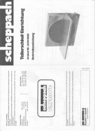
NOTE:<br />
__.<br />
CUT 7r'-DEEP RABBET TO<br />
Frr /r,,_THrcK plywooD \ -20 DRILL SERIES<br />
FIRSÏ NAIL METAL<br />
AROUND CYLINDER TOP<br />
SO TOP EDGE 15 FLUSH<br />
BOTTOM<br />
SUPPORT<br />
lr-<br />
ll-<br />
}|-<br />
Èr-<br />
Fr-<br />
1..<br />
}r<br />
!ala<br />
E<br />
F,<br />
F<br />
F