LBB 1965/00 Plena Message Manager - WES Components
LBB 1965/00 Plena Message Manager - WES Components
LBB 1965/00 Plena Message Manager - WES Components

Create successful ePaper yourself
Turn your PDF publications into a flip-book with our unique Google optimized e-Paper software.
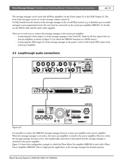
3 15 42GND23Input 1 PriorityLoopthrough 1Input 2 ProgramLoopthrough 2Input 1 Priority2..24V-Input 10V-Input 2Input 2 Enable2..24V-Enable0V-MuteSlave Input 1<strong>00</strong>V 1<strong>00</strong>V0GND13This apparatus must be earthedThis apparatus must be earthed<strong>Plena</strong> <strong>Message</strong> <strong>Manager</strong> | Installation and Operating Manual | External settings and connectionsen | 14The message manager can be used with all <strong>Plena</strong> amplifiers via the Cinch output (4) or the XLR Output (6). Thelevel of the messages can be set via the message volume control (2).To fully benefit from the features of the message manager in the overall <strong>Plena</strong> system (e.g. to distribute pre-recordedmessages to pre-programmed zones) the unit must be connected via the system pre-amplifier <strong>LBB</strong>1925. To do this,use the RS232 cable and the audio cable supplied.There are several ways to connect the message manager to the system pre-amplifier:- Connecting the Cinch output (4) of the message manager to the Cinch PC Audio In (R) line input of the systempre-amplifier, as shown in figure 3.2 (in which the <strong>LBB</strong>1961 functions as a BGM source).- Connecting the XLR output (6) of the message manager to the points 1 and 3 of the 8-pole DIN socket of thesystem pre-amplifier.3.3 Loopthrough audio connections<strong>LBB</strong>1920Dir.Out1 Dir.Out2 Dir.Out3 Dir.Out4 Ins/ Casc / Emgln Ins/ Casc Out Master Line Out Master Mic. Out115V230VIns/Casc<strong>LBB</strong> 1920/<strong>00</strong>89<strong>00</strong> 192 <strong>00</strong><strong>00</strong>5115/230V~,50/60HzNo.Apparatus deliviredconnected for 230V-1- 34 51- 34 5+- 1+- 21- 34 51- 34 51- 34 5WarningRated inputpower: 25VAT0,5AL250VLEMG OutDC InDC OutR1/Line 2/Line 3/Line4/Line+24V-+24V-<strong>LBB</strong><strong>1965</strong><strong>LBB</strong> <strong>1965</strong>/<strong>00</strong>89<strong>00</strong> 196 5<strong>00</strong>5Loop throughIn+ Msg Active TriggerInputSupervision C 24V NC C NO 1 2 3 4 5 6 7 8 9 10 11 12NC NOFault GNDPilottoneMainsRS232 to <strong>LBB</strong>1925Apparatus delivered connected for 230V~230V~ 50/60HzPilot <strong>Message</strong>ToneOutInOutTrigger Input 1-6OFFON12345678RS232 to PCWKS/NWarningRated InputPower:50VATo.5L250V<strong>LBB</strong>1938Input 1 Input 2 Slave InputPriority Enable 1<strong>00</strong>V+-+-1<strong>00</strong>V070V08ohmDirect O utput2..24V GND 2..24V GND 1<strong>00</strong>V 0Default Off Default OnInput 1-PriorityInput 2-Program1<strong>00</strong>V/70VPriority Only0No Priority01<strong>00</strong>V 0 70V 0 8Priority Controlled OutputPriority Only No PriorityPriorityInputLoopthroughInputLoopthrough1<strong>00</strong>V 0 1<strong>00</strong>V 0WarningThis apparatus must be earthedFigure 3.3It is possible to connect the <strong>LBB</strong><strong>1965</strong> message manager between a mixer pre-amplifier and a power amplifier.When the message manager is not active, the mixer pre-amplifier is routed to the power amplifier. However, whenthe message manager becomes active, this loopthrough connection is interrupted and the message manager isswitched to the power amplifier.Figure 3.3 shows this configuration example in which the <strong>Plena</strong> Mixer Pre-amplifier <strong>LBB</strong>1920 is used with a <strong>Plena</strong>Power Amplifier <strong>LBB</strong>1938. This is a high priority application, as the message manager has absolute priority.Bosch Security Systems | 2<strong>00</strong>3-09 | 9922 141 50502en