OCEAN/ESS 410 1 Lab 12. Earthquake Focal Mechanisms You can ...
OCEAN/ESS 410 1 Lab 12. Earthquake Focal Mechanisms You can ...
OCEAN/ESS 410 1 Lab 12. Earthquake Focal Mechanisms You can ...

Create successful ePaper yourself
Turn your PDF publications into a flip-book with our unique Google optimized e-Paper software.
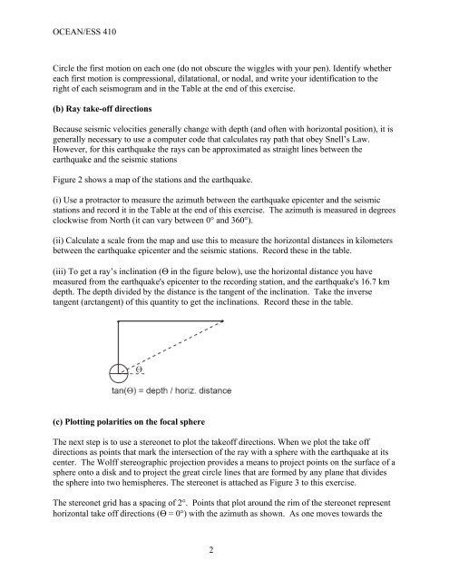
<strong>OCEAN</strong>/<strong>ESS</strong> <strong>410</strong>Circle the first motion on each one (do not obscure the wiggles with your pen). Identify whethereach first motion is compressional, dilatational, or nodal, and write your identification to theright of each seismogram and in the Table at the end of this exercise.(b) Ray take-off directionsBecause seismic velocities generally change with depth (and often with horizontal position), it isgenerally necessary to use a computer code that calculates ray path that obey Snell’s Law.However, for this earthquake the rays <strong>can</strong> be approximated as straight lines between theearthquake and the seismic stationsFigure 2 shows a map of the stations and the earthquake.(i) Use a protractor to measure the azimuth between the earthquake epicenter and the seismicstations and record it in the Table at the end of this exercise. The azimuth is measured in degreesclockwise from North (it <strong>can</strong> vary between 0° and 360°).(ii) Calculate a scale from the map and use this to measure the horizontal distances in kilometersbetween the earthquake epicenter and the seismic stations. Record these in the table.(iii) To get a ray’s inclination (Θ in the figure below), use the horizontal distance you havemeasured from the earthquake's epicenter to the recording station, and the earthquake's 16.7 kmdepth. The depth divided by the distance is the tangent of the inclination. Take the inversetangent (arctangent) of this quantity to get the inclinations. Record these in the table.(c) Plotting polarities on the focal sphereThe next step is to use a stereonet to plot the takeoff directions. When we plot the take offdirections as points that mark the intersection of the ray with a sphere with the earthquake at itscenter. The Wolff stereographic projection provides a means to project points on the surface of asphere onto a disk and to project the great circle lines that are formed by any plane that dividesthe sphere into two hemispheres. The stereonet is attached as Figure 3 to this exercise.The stereonet grid has a spacing of 2°. Points that plot around the rim of the stereonet representhorizontal take off directions (Θ = 0°) with the azimuth as shown. As one moves towards the2