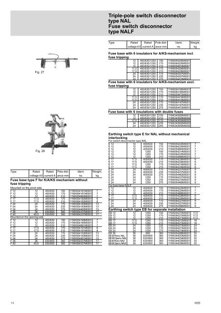
Triple-pole switch disconnectortype <strong>NAL</strong>Fuse switch disconnectortype <strong>NAL</strong>FType Rated Rated Pole dist- Ident. Weight,voltage kV current A ance mm no. kgFig. 27Fig. 28Type Rated Rated Pole dist- Ident. Weight,voltage kV current A ance mm no. kgFuse base type F for K/A/KS mechanism withoutfuse trippingMounted on the pivot sideF 12 12 400/630 150 1YMX054181M0001 7F 12 12 400/630 170 1YMX064181M0001 7F 12 12 400/630 210 1YMX054960M0001 7F 17 17,5 400/630 170 1YMX054182M0001 8F 17 17,5 400/630 210 1YMX064182M0001 8F 24 24 400/630 170 1YMX064183M0001 13F 24 24 400/630 235 1YMX054183M0001 13F 24 24 400/630 275 1YMX054460M0001 13F 36 36 630/800 360 1YMX054337M0001 17F 40 40,5 630/800 360 1YMX064337M0001 17Mounted on the opening sideF 12 12 400/630 150 1YMX054190M0001 7F 12 12 400/630 170 1YMX064190M0001 7F 12 12 400/630 210 1YMX054961M0001 7F 17 17,5 400/630 170 1YMX054191M0001 8F 17 17,5 400/630 210 1YMX064191M0001 8F 24 24 400/630 170 1YMX064193M0001 13F 24 24 400/630 235 1YMX054193M0001 13F 24 24 400/630 275 1YMX054461M0001 13F 36 36 630/800 360 1YMX054337M0001 17F 40 40,5 630/800 360 1YMX064337M0001 17Fuse base with 6 insulators for A/KS-mechanism incl.fuse tripping12 400/630/1250 150 1YMX054205M000112 400/630/1250 170 1YMX064205M000112 400/630/1250 210 1YMX054974M000117,5 400/630/1250 170 1YMX054206M000117,5 400/630/1250 210 1YMX064206M000124 400/630/1250 170 1YMX064207M000124 400/630/1250 235 1YMX054207M000124 400/630/1250 275 1YMX054474M0001Fuse base with 6 insulators for A/KS-mechanism excl.fuse tripping12 400/630/1250 150 1YMX054185M000112 400/630/1250 170 1YMX064185M000112 400/630/1250 210 1YMX054972M000117,5 400/630/1250 170 1YMX054418M000117,5 400/630/1250 210 1YMX064418M000124 400/630/1250 170 1YMX064187M000124 400/630/1250 235 1YMX054187M000124 400/630/1250 275 1YMX054472M0001Fuse base with 6 insulations with double fuses12 400/630/1250 150 1YMX343555M000112 400/630/1250 210 1YMX343555M000417,5 400/630/1250 170 1YMX343555M000224 400/630/1250 235 1YMX343555M000324 400/630/1250 245 1YMX343555M0005Earthing switch type E for <strong>NAL</strong> without mechanicalinterlockingFor switch disconnector type <strong>NAL</strong>E 12 12 400/630 150 1YMX054235M0001 7E 12 12 400/630 170 1YMX064235M0001 7E 12 12 400/630 210 1YMX054983M0001 7E 12 12 1250 150 1YMX054214M0001 7E 12 12 1250 170 1YMX064235M0002 7E 12 12 1250 210 1YMX054989M0001 7E 17 17,5 400/630 170 1YMX054236M0001 8E 17 17,5 400/630 210 1YMX064236M0001 8E 17 17,5 1250 170 1YMX054218M0001 8E 17 17,5 1250 210 1YMX064236M0002 8E 24 24 400/630 170 1YMX064237M0001 9E 24 24 400/630 235 1YMX054237M0001 9E 24 24 400/630 275 1YMX054483M0001 9E 24 24 1250 170 1YMX064237M0002 9E 24 24 1250 235 1YMX054219M0001 9E 24 24 1250 275 1YMX054489M0001 9For fuse base <strong>NAL</strong>FE 12 12 400/630 150 1YMX054225M0001 7E 12 12 400/630 170 1YMX064225M0001 7E 12 12 400/630 210 1YMX054988M0001 7E 17 17,5 400/630 170 1YMX054226M0001 8E 17 17,5 400/630 210 1YMX064226M0001 8E 24 24 400/630 170 1YMX064227M0001 9E 24 24 400/630 235 1YMX054227M0001 9E 24 24 400/630 275 1YMX054488M0001 9Earthing switch type EB for separate installationEB 12 12 1250 150 1YMX054270M0001 17,5EB 12 12 1250 170 1YMX064270M0001 17,5EB 12 12 1250 210 1YMX054271M0001 17,5EB 17 17,5 1250 170 1YMX054272M0001 19EB 17 17,5 1250 210 1YMX064272M0001 19EB 24 24 1250 235 1YMX054273M0001 24EB 24 24 1250 170 1YMX064273M0001 24EB 24 24 1250 275 1YMX054274M0001 24EB 36 36 800 360 1YMX054288M0001 30EB 36 Pivot s. <strong>NAL</strong> 36 630/800 360 1YMX344033M0001 30EB 36 Open s. <strong>NAL</strong> 36 630/800 360 1YMX344034M0001 30EB 36 Pivot s. <strong>NAL</strong>F 36 630/800 360 1YMX344035M0001 30EB 36 Open s. <strong>NAL</strong>F 36 630/800 360 1YMX344036M0001 3014ABB
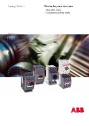
Triple-pole switch disconnectortype <strong>NAL</strong>Fuse switch disconnectortype <strong>NAL</strong>FFig. 29Fig. 31Fig. 30Fig. 34Fig. 32Fig. 33Fig. 3514. OPERATING EQUIPMENT AND OPTIONSDescription Type Ident. Wt,no. kgMechanismsK-mechanism K 12 1YMX054165M0001 5K-mechanism K 17 1YMX038658M0001 5K-mechanism K 24 1YMX054167M0001 5K-mechanism K 36 1YMX054340M0001 5K-mechanism K 40 1YMX054340M0001 5A-mechanism A 12 1YMX054173M0001 7A-mechanism A 17 1YMX054174M0001 7A-mechanism A 24 1YMX054175M0001 7A-mechanism A 36 1YMX051341M0001 7A-mechanism A 40 1YMX051341M0001 7KS-mechanism*) KS 12/17 1YMX054168M0001 6KS-mechanism*) KS 24 1YMX054171M0001 6KS-mechanism KS 36 1YMX054342M0001 6KS-mechanism KS 40 1YMX054342M0001 6Plastic cover for A-mechanism 1YMX241351M0001 0,2Description Type Ident. Wt,no. kgHand operating mechanism type HE with accessoriesFront bearing for HE, with cardanic joint 1YMX053233M0001 1.6Front bearing for HE, without cardanic joint 1YMX053233M0002 0.8Front bearing for HE, for motor operating 1YMX042249M0004 1,6Bevel gear for HE 1YMX053362M0001 1.4Operating handle for HE 1YMX053235M0001 0.6Operating handle for HE, armoured 1YMX053235M0004 1,8Front bearing for HE, with blocking coil, 220 V AC 1YMX053393M0001 2.1Front bearing for HE, with blocking coil, 110 V AC 1YMX053394M0001 2.1Front bearing for HE, with blocking coil, 220 V DC 1YMX053395M0001 2.1Front bearing for HE, with blocking coil, 110 V DC 1YMX053396M0001 2.1Front bearing for HE, with blocking coil, 48 V DC 1YMX053397M0001 2.1Front bearing for HE, with blocking coil, 24 V DC 1YMX053398M0001 2.1Shaft extension for left-hand side operation:– for pole distance 150 mm 1YMX054357M0001 1.9– for pole distance 210 mm 1YMX054353M0001 2.3– for pole distance 170 mm (12 kV) 1YMX054358M0002 2.1– for pole distance 170 mm (17,5 and 24 kV) 1YMX054358M0001 2.1– for pole distance 235 mm 1YMX054359M0001 2.6– for pole distance 275 mm 1YMX054355M0001 3.1– for pole distance 360 mm 1YMX343226M0004 4.0Connection kit for shaft extension assembing 1YMX000054M0001 0,1Connection rod 490 mm 1YMX053346M0008 0,8Connection rod 550 mm 1YMX053346M0009 0,9Connection rod 570 mm 1YMX053346M0010 1,0Connection rod 1300 mm 1YMX053346M0002 1,9Connection rod 2000 mm 1YMX053347M0001 2,9Connection rod 1300 mm, insulated 1YMX000012M0001 2,1Connection rod 2000 mm, insulated 1YMX000012M0002 3,1Connection rod 1300 mm, armoured and insulated 1YMX000012M0003 2,9Connection rod 2000 mm, armoured and insulated 1YMX000012M0004 4,2Connection rod 668 mm, insulated CZ 1YMX000012M0005 1,2Connection rod 738 mm, insulated CZ 1YMX000012M0006 1,3Connection rod 1300 mm, armoured and insulated CZ 1YMX000012M0007 2,9Connection rod 2000 mm, armoured and insulated CZ 1YMX000012M0008 4,2Connection rod 1300 mm, armoured 1YMX000004M0003 2,7Connection rod 2000 mm, armoured 1YMX000004M0004 4,0Connection rod 1300 mm, armoured CZ 1YMX000004M0007 2,7Connection rod 2000 mm, armoured CZ 1YMX000004M0008 4,0Crank arm1YMX053225M0001Operating rod 1YMX053001M0001 0.7Shaft extension 470 mm 1YMX053348M0001 1.7Shaft extension 380 mm 1YMX053349M0001 1.4Joint link for shaft extension 1YMX053350M0001 0.2Support bearing for <strong>NAL</strong>/<strong>NAL</strong>F 12 1YMX053351M0001 1.8Support bearing for <strong>NAL</strong>/<strong>NAL</strong>F 17/24 1YMX053352M0001 1.9Support bearing for <strong>NAL</strong> 12 with E 12 1YMX053353M0001 2.2Support bearing for <strong>NAL</strong> 17/24 with E 17/24 1YMX053354M0001 2.8Support bearing for F 12 with E 12 1YMX053355M0001 1.3Support bearing for F 17/24 with E 17/24 1YMX053356M0001 1.4Test fuseAdjustable length 3, 6/36 kV with striker pin1YMX300062M0001Mechanical interlocking for earthing switch *)– on <strong>NAL</strong> 12 1YMX054275M0001 2,5– on <strong>NAL</strong> 17/24 1YMX054276M0001 3,1– on <strong>NAL</strong>F 12 Fuse length dim. e = 292 mm 1YMX054277M0001 5,7– on <strong>NAL</strong>F 12 Fuse length dim. e = 192 mm 1YMX054278M0001 5,0– on <strong>NAL</strong>F 12 Fuse length dim. e = 442 mm 1YMX054279M0001 6,4– on <strong>NAL</strong>F 17 Fuse length dim. e = 292 mm 1YMX054280M0001 6,3– on <strong>NAL</strong>F 17 Fuse length dim. e = 442 mm 1YMX054281M0001 7,0– on <strong>NAL</strong>F 24 Fuse length dim. e = 442 mm 1YMX054282M0001 6,5– on <strong>NAL</strong>F 24 Fuse length dim. e = 537 mm 1YMX054283M0001 7,3– on <strong>NAL</strong> 36/40 RB on pivot side 1YMX343986M0002 5,4– on <strong>NAL</strong> 36/40 RB on opening side 1YMX343986M0001 3,3– on <strong>NAL</strong>F 36/40 RB on pivot side 1YMX343986M0003 9,4– on Nale 36/40 RB on opening side 1YMX343986M0004 7,6*) Normally, interlocking is mounted on the left hand side of the switch andtherefore a shaft for left hand operation is needed.Fig. 29 A-mechanismFig. 30 K-mechanismFig. 31 KS-mechanismFig. 32 Front bearing for HEFig. Bevel gear for HEFig. 34 Mechanical interlockingFig. 35 Auxiliary switchABB 15