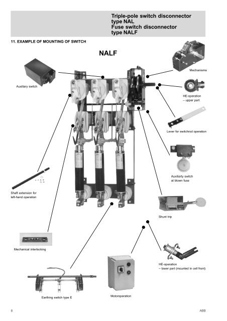
Triple-pole switch disconnectortype <strong>NAL</strong>Fuse switch disconnectortype <strong>NAL</strong>F11. EXAMPLE OF MOUNTING OF SWITCH<strong>NAL</strong>FMechanismsAuxiliary switchHE-operation– upper partLever for switchrod operationAuxiliarty switchat blown fuseShaft extension forleft-hand operationShunt tripMechanical interlockingHE-operation– lower part (mounted in cell front)Earthing switch type EMotoroperation8ABB
12. TECHNICAL SPECIFICATIONSTriple-pole switch disconnectortype <strong>NAL</strong>Fuse switch disconnectortype <strong>NAL</strong>FTABLE I<strong>Switch</strong> disconnector type <strong>NAL</strong>The switch disconnector complies with IEC publications 129, 254 and 694 concerning general purpose switches, IEC publication 420regarding correct co-operation between switch disconnector and fuse.Rated voltage Un kV 12 kV 17,5 kV 24 kV 36 kV 40,5 kVRated current In A 400 630 1250 400 630 1250 400 630 1250 630 800 630 800Max. rated current I A 400 630 1150 400 630 1150 400 630 1150 630 800 630 800Short circuit making capacity Ima kA peak 67 67 67 50 50 50 50 50 50 50 50 50 50Peak withstand current Idyn kA peak 82 82 82 82 82 82 62,5 62,5 82 66 66 66 66Short time current 1 sec. Ith kA eff 31,5 31,5 31,5 31,5 31,5 31,5 31,5 31,5 31,52 sec. " " 25 25 25 25 25 25 25 25 25 25 25 25 253 sec. " " 20 20 20 16 16 16Mainly active load breaking capacity 2)(test duty 1 and 2, IEC 265) I A 400 630 1250 400 630 1250 400 630 1250 630 800 630 800Mainly capacitive breaking capacity(test duty 4, IEC 265) I A 150 150 150 45 45 45 80 80 80 50 50 50 50Mainly inductive breaking capacitycos ϕ = 0,15 A 16 16 16 16 16 16 16 16 16 16 5) 16 5) 16 5) 16 5)Rated earth fault breaking capacity, IEC 265Earth fault breaking capacity, fig. 6 I A 150 150 150 70 70 70 75 75 75Capacitive breaking capacity, fig. 7 I A 90 90 90 40 40 40 31,5 31,5 31,5 50 50 50 50Max. breaking capacity in co-operation withfuses (IEC 420 1990-11) A 1600 1600 1600 1600 900 900 300 300 300 300Max. fuse size 4) In A 125 125 125 125 80 80 40 40 40 40Power frequency withstand voltage 50 Hz 1 min.- to earth and between poles kV 42 45 55 80 95- across isolating distance kV 48 60 70 88 120Impulse withstand voltage 1,2/50 us.- to earth and between poles kV 75 95 125 170 190- across isolating distance kV 85 110 145 195 220Pole distance P mm 150, 170 and 210 170 and 210 170 6) , 235 and 275 360Max. operating torque at:- closing K/A mech. Nm 115 - 120 Nm 80 - 100 Nm- opening K/A mech. Nm K-mech. 120 Nm / A-mech. 3 Nm K-mech 80 - 100 NmOperating angle on the shaft degrees 130 120Opening time ms 40 - 60 60Arc time ms 10 - 20 35Earthing switch type E 1) for <strong>NAL</strong>/<strong>NAL</strong>F and type EBRated voltage Un kV 12 17,5 24 36Peak withstand current 3) Idyn. kA peak 62/82 40/82 38/82 66Short time current 1 sec. Ith kA eff 31,5 31,5 31,52 sec. " " 25 25 253 sec. " " 20 16Short circuit making capacity 3) Ima kA peak 62/67 40/62,5 38/50 50Test voltage 50 Hz 1 min. kV 42 45 55 80Power frequency withstand voltage 1,2 / 50 us. kV 82 95 125 170Pole distance P mm 175 and 210 170 and 210 170, 235 and 275 3601)Mechanical interlocking can be fitted, but not for KS-mechanism.2)At In = 630 A, 100 x CO. At In = 1250 A, 20 x CO.3)When fed from switch disconnector/earthing switch side.4)Max. fuse size is ref. to time current characteristics for CEF.5)Power factor =0,16)With insulating barriersABB 9