Captain Sim 'Legendary C-130' - Flight Tutorial - e-HAF
Captain Sim 'Legendary C-130' - Flight Tutorial - e-HAF
Captain Sim 'Legendary C-130' - Flight Tutorial - e-HAF

Create successful ePaper yourself
Turn your PDF publications into a flip-book with our unique Google optimized e-Paper software.
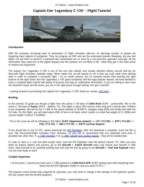
FS Station – www.fsstation.com<strong>Captain</strong> <strong>Sim</strong> <strong>'Legendary</strong> C-<strong>130'</strong> - <strong>Flight</strong> <strong>Tutorial</strong>IntroductionWith the everyday increasing level of automation of <strong>Flight</strong> <strong>Sim</strong>ulator add-ons, an alarming number of people areforgetting basic aspects of navigation. They can program an FMC and use the automated systems flawlessly, but you hadbetter not ask them to perform a standard-rate coordinated turn or even fly a non-precision approach manually. All theinformation they need are on the digital displays and the systems are not likely to fail - what they get is this false senseof realism and enjoyment.The <strong>Captain</strong> <strong>Sim</strong> <strong>'Legendary</strong> C-<strong>130'</strong> is one of the very few realistic and visually detailed military aircraft add-ons forMicrosoft <strong>Flight</strong> <strong>Sim</strong>ulator available today. What makes this aircraft special to me is that you truly need some pilotingskills in order to complete a successful fight - it's no rocket science, but it's certainly harder than pushing the rightbuttons at the right times! Due the <strong>'Legendary</strong> C-<strong>130'</strong> great complexity and the huge popular request, we have decided towrite a complete flight tutorial with plenty of pictures and easy to understand information. If you are willing to learn howthis beautiful classic aircraft works, you are in the right place! Enough talking, let's get it started!- Looking forward to purchasing the <strong>Captain</strong> <strong>Sim</strong> <strong>'Legendary</strong> C-<strong>130'</strong>? Read our review: click here! -BriefingIn this tutorial, I'll guide you though a flight from the active C-130 base of Little Rock (KLRF - Jacksonville, AK) to theactive C-130 base of Dyess (KDYS - Abilene, TX). This flight is about 450 nautical miles long and it should take 1h30minto be completed. We will fly the C-130E at the typical altitude of 20,000 ft, navigate using VORs and finally land with theILS help. For this flight, you will need about 45% of fuel on all tanks, which results in a total fuel weight of 21,100lbs anda gross weight of about 110,000lbs.This is the route we will be following in this flight: KLRF (departure airport) -> LIT (113.90) -> BYP (114.60) ->FUZ (115.70) -> ABI (113.70) -> KDYS (arrival airport)If you would like to use FS ATC, please download the IFR <strong>Flight</strong>plan. After the download is complete, move the file toyour "My Documents\<strong>Flight</strong> <strong>Sim</strong>ulator Files" directory. I'd also like to recommend that you download (and print, ifpossible) two other files: 1. C-130E Checklist // 2. C-130E Takeoff and Landing Speeds - they will be needed later.In order to start in a cold and dark cockpit state, load the IFR <strong>Flight</strong>plan with the default Cessna 172. After you shutdown its engine, battery and avionics, go to the Aircraft > Select Aircraft menu and choose your favorite C-130Elivery. Slew yourself to an available parking spot and load the fuel by going to the Aircraft > Fuel and Payload menu.You are now ready to start!Cockpit inspection! At this point, I assume you have your C-130E parked at a Little Rock AFB (KLRF) parking spot with everything shutdown and the IFR <strong>Flight</strong>plan loaded in case you want FS ATC !The airplane comes almost fully prepared for operation, you only need to change a few settings in the hydraulic system,the fuel system and the throttle quadrant.FS Station – www.fsstation.comPage 1 of 20
FS Station – www.fsstation.com- In the hydraulic system (R1 icon):1. BRAKE SELECT switch - EMERGENCYThat will force the airplane to supply auxiliary hydraulic pressure (rather than utility hydraulic pressure) to the brakes,allowing them to be used with the engines off.2. ANTI-SKID switch - OFFAnti-skid will not function when the brake system is operating from the auxiliary hydraulic pressure (engines off) or whenthe parking brake is set.- In the throttle quadrant (propeller icon):1. TEMP DATUM CONTROL VALVES switches - AUTOPermits normal operation of the electronic temperature datum control system.2. Condition levers, throttles – GRD STOP, GRD IDLEThis ensures the blade angle is set to minimum thrust and that the engines will not start. Nacelle preheat is operable inthis configuration.Before startAfter you have inspected the aircraft's interior and exterior, it's time to power it up and put some light into the darkcockpit. In this stage, we will configure several systems in order to get the aircraft ready for engine startup.We have basically two ways of powering the aircraft: using external power from an ground power cart or using thebattery. For this tutorial, we will use ground power, but you may also use the battery if you want to. Go to the <strong>Captain</strong><strong>Sim</strong> menu and activate the ground power unit - a green bar will appear to confirm your selection. It's time to power it upand start systems configuration.- In the electrical system (upper OH icon):FS Station – www.fsstation.comPage 2 of 20
FS Station – www.fsstation.com1. External AC power switch - EXT AC PWRMatch the knob's yellow stripe with the panel's yellow stripe. That will connect external power to the AC distributionsystem. When using the battery, this switch remains in the OFF position.2. External DC power switch - EXT DC PWRMatch the knob's green stripe with the panel's green stripe. That will connect external power to the DC bus. If you aregoing to use the battery, place the switch in the BATTERY position.3. Turn the instrument and panel lights onNow that you have electrical power, make instruments more clear by turning lights on. The lights on/off switches arelocated on the pilot's side shelf (virtual cockpit)4. *Only when using the battery* Bus tie switch - TIEDProvides a mean for powering the main ac bus from the ATM generator during ground operation with no engine-drivengenerators supplying power. This is not needed when using external power, since it also powers the AC bus.5. Inverters - OFFBoth "Copilot AC Instruments" and "AC instrument and Engine" switches should be placed in the OFF position until wehave electrical power.- In the radio stack (tower icon):1. Radios - ONNot much to say here. With the radios on, you can communicate with ATC and change frequencies.Now that you have electrical power, it's time to start the Gas Turbine Compressor (GTC). The GTC supplies air for groundoperation of the air turbine motor, engine starting, nacelle preheat and air-conditioning systems. It is essential for acorrect engine startup and makes possible the ATM (Air Turbine Motor) operation, for those of you using the battery. TheATM supplies AC power to the aircraft (battery supplies DC power) - it will not be needed if you are using external power,since it also powers the AC bus.- In the GTC control panel (upper OH icon):1. Start GTC - STARTINGThis require several steps:1.1. Open the GTC intake door in order to allow GTC startup. The "NOT CLOSED" indicator should illuminate.1.2. Turn the GTC control switch to the START position. It will go back to "RUN" and the "START" light goes on.1.3. Wait until the ON SPEED light goes on. This light indicates that the GTC is operating normally and load can finally beapplied.1.4. Open the bleed air valve. This forces the GTC to supply air to the bleed-air system, which will be used to pressurizeand climatize the aircraft, and also for engine startup.FS Station – www.fsstation.comPage 3 of 20
FS Station – www.fsstation.com2. *Only when using the battery* START ATM - STARTINGThis require two steps:2.1. Start the ATM by placing the ATM control switch to the ON position.2.1. Connect the ATM generator by placing the generator switch in the RESET, ON position. This will supply power to theessential AC bus.- In the electrical system (upper OH icon):1. Inverters - SETThis require two steps:1.1. Copilot inverter switch - ESSENTIAL AC BUSKnob's yellow stripe matching with panel's yellow stripe.1.2. AC INST & ENGINE FUEL CONTROL INVERTER switch - ESSENTIAL DC BUSKnob's yellow stripe matching with panel's green stripe.At this point, you will see that the OFF flag on the attitude indicator has disappeared. Let's continue with theconfiguration...- In the lower overhead panel (lower OH icon):1. Fuel enrichment switches - OFF2. Oil cooler flaps - AUTOMATICThis settings leaves to the aircraft the function of opening and closing the oil cooler flaps. In temperatures above 27ºC,leave the oil cooler flaps completely open.- In the hydraulic system (R1 icon):1. SUCTION BOOST PUMP switches - ON/LIGHTS OUTAfter you turn the suction boost pumps on, make sure its warning lights have gone off.2. AUX PUMP switch - ONWith the auxiliary pump on, you will be able to use the emergency brake system to brake the aircraft until the enginesare started.FS Station – www.fsstation.comPage 4 of 20
FS Station – www.fsstation.com--- RUN THE BEFORE STARTING CHECKLIST ---Starting enginesYou have successfully configured the aircraft for engine start now. At this point, we will start all four engines (in the 3-4-2-1 sequence) and make some of the final configurations of the aircraft's systems before starting taxi. You many nowturn your anti-collision lights on - they indicate that the engines are being started. Let's proceed with engine start!- In the throttle quadrant (virtual cockpit only):1. Low Speed Ground Buttons - LOWThe low speed ground buttons are only available in the virtual cockpit. Lowering them will downshift the engines,reducing the RPM and therefore wear. After the engine is stable, you can up the buttons and connect the generator.- In the bleed air system (upper OH icon):1. Engine bleed air switch - OPENThis will provide bleed air for the engine to start.- In the throttle quadrant (propeller icon):1. Condition lever - RUNIn the RUN position, the engine will attempt a start when the start button is pushed.FS Station – www.fsstation.comPage 5 of 20
FS Station – www.fsstation.comYou can now go to the lower overhead panel (lower OH icon) and press the engine ground start button for the engineyou want to start. Hold the button until you see a rise in the engine's parameters, then release it and wait for the engineto stabilize. You have just started the first engine!- In the electrical system (upper OH icon):1. Engine generator switch - ONRemember to up the ground speed low buttons now. Place the switch in the RESET position, then ON. The engine will beused to provide electrical power to the aircraft when the generator is online.2. DC power switch - BATTERYSince external power will be disconnected soon and electrical power is available from the generator, switch the DC powerswitch to the BATTERY position.- In the GTC control panel (upper OH icon):1. Close the bleed air valveWe will now use the bleed air coming from the engine #1 to start all other engines. The GTC bleed air is not neededanymore.* Start engine #4 using the procedures marked in red color *FS Station – www.fsstation.comPage 6 of 20
FS Station – www.fsstation.com- In the GTC control panel and in the electrical system (upper OH icon):1. Disconnect the ATM generator (battery users only)2. Stop the ATM (battery users only)The ATM will not be needed anymore, the engines are now powering the aircraft.3. Stop the GTCThis requires two other steps:3.1. Turn the GTC control switch to the OFF position.3.2. Close the GTC door- In the pressurization system (upper OH icon):1. Air conditioning master switch – AIR COND NO PRESSThis setting will turn the air conditioning on, but not yet pressurize the aircraft.- In the electrical system (upper OH icon):1. External AC power switch - OFFThis will disconnect external power from the AC distribution system. The engines providing power to the aircraft.You can now go the the <strong>Captain</strong> <strong>Sim</strong> menu and remove external power. You no longer need external power since yourengines 1 and 2 are started and there is enough power onboard already.* Start engine #2 and #1 using the procedures marked in red color *--- RUN THE STARTING ENGINES CHECKLIST ---FS Station – www.fsstation.comPage 7 of 20
FS Station – www.fsstation.comBefore taxiWe now have the engines started, but we are not yet ready to fly. We still need to configure the instruments and preparethe navigation equipment - it's not nice to get lost when you're airbone! Everything must be perfect before takeoff.Let's review our flighplan first: KLRF (departure airport) -> LIT (113.90) -> BYP (114.60) -> FUZ (115.70) ->ABI (113.70) -> KDYS (arrival airport)You can start by tuning the clearance delivery (132.80) frequency and requesting an IFR clearance. Take note of therunway in use, the squawk code and the local altimeter pressure. After obtaining the clearance, we can work on settingup the aircraft for VOR navigation and also configure the transponder.- In the radio stack (tower icon):Tune the VOR frequency for the LITTLE ROCK VOR (LIT - 113.90) on both NAV1 and NAV2 radios. With thefrequency tuned, the aircraft will get DME and bearing information from this VOR. You will be able to track a selectedradial and know your distance from the station in the HSI (horizontal situation indicator), located in the main panel. Wewill discuss how to navigate later on the tutorial.- In the IFF/SSR panel (SSR icon):1. Set the squawk code you received from the controller using the MODE 3/A/B code select switches2. Place the Mode C switch in the ON position3. Turn the Mode 3/A knob to the 3/A position4. Turn the Master Control knob to the STBY positionThese four steps will set the transponder and place it in standby mode. It will also allow controllers to know your presentaltitude.Now that you have tuned the VOR, it's time to set the radial you want to follow. Since you want to go directly from theLITTLE ROCK VOR (LIT) to the BONHAM VOR (BYP), your only option is to track the 246 radial from the formerstation. More detailed instructions on how to get to the LITTLE ROCK VOR and how to navigate will be presented later.You will also want to set the heading bug to the runway's heading - it will help you keep the same heading after takeoff.FS Station – www.fsstation.comPage 8 of 20
FS Station – www.fsstation.com- In the Horizontal Situation Indicator, Radar Altimeter and Barometric Altimeter (pilot's panel or copilot's panel - L or R icon):1. Turn the COURSE SET knob until the course selector window reads 2462. Turn the HEADING SET knob until the heading bug is pointing to the active runway's heading3. Rotate the Radar Altimeter knob to put it into operationThe radar altimeter measures your height. It is very useful for ILS approaches, as the decision height is given in "feetabove ground level".4. Ensure the Barometric Altimeter is properly configured with the local altimeter setting by rotating its small knob.Having the local altimeter setting correctly configured avoids altitude indication errors.- In the flap control system (flap icon):1. Set the flaps to 50%Fifty percent is the normal take-off flap position. All normal take-offs are made with this flap setting.Taxi--- RUN THE BEFORE TAXI CHECKLIST ---With the engines started and the instruments configured, we finally have permission to leave the stand and taxi to theactive runway! However, we still need to configure a few systems before and during taxi. Because of the wind direction,I'll be taxiing to the runway 7.- In the hydraulics system (R1 icon):1. Brakes - NORMAL / ANTI-SKID ONSince all engines are started and we have utility hydraulic pressure, change the brake system to normal and turn anti-skidon. Check if they are working properly.Before taxi, a good practice is to downshift the outboard engines to low speed ground idle, just like we did before enginestart. They reduce the engine's wear and also reduce the total power of the aircraft, allowing us to taxi at lower speeds.The engines will be automatically upshifted when takeoff power is applied.It is finally to taxi! If the aircraft is parked in a position that requires pushback, use reverse thrust to move the aircraftbackwards. Yes, reverse thrust... you won't need a pushback cart, since the engines are powerful enough to even allowparallel parking! Once you get far enough, use forward thrust to start taxiing to the active runway. There is nothing muchto say about taxiing... just follow your assigned taxiways, maintain a fair speed and try not to use the brakes very often.There are, however, many items that need to be checked or configured while taxiing.FS Station – www.fsstation.comPage 9 of 20
FS Station – www.fsstation.com- General:1. Turn the taxi lights on2. Check if all doors are closed3. Check if the flaps are set to 50% (take-off configuration)4. Check if engine instruments are all in the green bandThe green band indicates that a specific indication is operating normally.5. Check if the flight controls are free and responding to inputs by moving the yoke in all positions6. Check if the radios are set and the NAV1/NAV2 are tuned with the LITTLE ROCK VOR frequency (113.90)7. Check if the instruments (HSI, altimeter, radio altimeter, etc.) are set and operating normally- In the pressurization system (upper OH icon):1. Cabin Pressure Controller - 6000 FEETSince we'll be flying in FL200 and there is not much oxygen there, we need to pressurize the cabin. Setting the cabinpressure to 6000ft will allow passengers to breath normally.2. Air conditioning master switch – AIR COND AUTO PRESSThe cabin will be climatized and automatically pressurized to 6000ft. No matter how high we go, the passengers willbreath just like they were at 6000ft.- In the electrical system:1. Check if all generators are on (except for the ATM generator) and the GTC is offThat will ensure that all engines are providing electrical power to the aircraft.2. DC bus tie switch - NORMALOnly if you had tied the switch before. The main AC bus is now being powered by the engines...- In the anti-icing system (upper OH icon):1. NESA windshield switches - NORMALThe NESA is used to heat the cockpit's windshield and windows in order to prevent icing.2. PITOT HEAT switches - ONThe pitot heat prevents ice from forming in the pitot tubes. If ice build into the tube, vital instruments such as the verticalspeed indicator, airspeed indicator, etc. will be lost.3. PROP & ENG ANTI-ICING - ONPrevents ice from building in the propellers. With the master switch in the auto position, the system will only be activatedwhen icing conditions exist.FS Station – www.fsstation.comPage 10 of 20
FS Station – www.fsstation.com4. ENGINE INLET AIR DUCT ANTI-ICING - ONPrevents ice from building in the engine inlet air duct. With the master switch in the auto position, the system will only beactivated when icing conditions exist.- In the IFF/SSR panel (SSR icon):1. Turn the Master Control knob to the NORM positionAllows operation of system at normal receiver sensitivity. It will also allow controllers to know your present altitude andlocation.Finally, we'll configure the TCAS (Traffic Alert Avoidance System):- In the TCAS panel (Rdr icon):1. Function selector switch – TCASThis will turn the radar on. You will see the radar display lights up and traffic start to show up - resolution advisory is alsoactive. We didn't turn the TCAS on before because its antenna emits radiation, which is hazardous to the groundpersonnel. Refer to the manual for proper TCAS usage.A little break for the take-off briefing!--- RUN THE TAXI CHECKLIST ---This is probably the most important part of the tutorial yet. You may very well know how to prepare the aircraft fortakeoff, but it is extremely important that you have it very clear in your mind what to do in case of an emergency andhow to start navigation! Please read this section carefully - after all this preparation, you most likely don'twant to get lost in the skies!Before entering the runway, you need to figure out your takeoff speed. Find your VTO using the "C-130E Takeoff andLanding Speed" chart you downloaded - note that the speeds are directly proportional to the gross weights and all dataare based on a flap 50% configuration. My takeoff speed will be 96 knots, since my aircraft's gross weight is 110,000lbs.Now that you have this information, it's time to brief the takeoff procedure!As you enter the runway, turn the strobe lights on - they inform the tower and other aircraft that you are entering anactive runway. Soon after you are given a takeoff clearance, gradually advance the throttles toward maximum power andmove the yoke column slightly forward in order to increase steering effectiveness. At a speed of 50~60 knots, move theyoke column back to neutral. You should also use the rudder to steer the aircraft on the runway until lift-off. As soon asyou reach the takeoff speed (96 knots in my case), pull back on the yoke and start the rotation. Initially, rotate to anattitude of 5~7 degrees pitch up (keep that until clear of the ground), then to an attitude that allows you to maintain theinitial climb speed (20~30 knots above takeoff speed) at takeoff thrust - that will be around 15 degrees. Make thenecessary corrections as you climb.When airbone, retract the landing gear and keep climbing at the initial climb speed (20~30 knots above takeoff speed).Also, maintain the runway heading (you have the heading bug set on the HSI) until crossing the airport's boundary. NowI want you to meet the radio magnetic indicator (RMI) - it will be essential for us to start navigating!The RMI is a green instrument located on the bottom-right side of the panel composed by two arrows (one big, onesmall). Its main purpose is to indicate the location of a VOR or NDB station - the arrow will point to the direction theFS Station – www.fsstation.comPage 11 of 20
FS Station – www.fsstation.comstation is located. "How does that help me?", you ask... well, we need to know where the LITTLE ROCK VOR is locatedso that we can track one of its radials (radial 246 for this flight). Without a RMI, it would be impossible to track thisradial; we simply wouldn't know where the station is!Just after takeoff, you'll notice that the larger RMI needle is pointing to the side. What you need to do is turn (aftercrossing the airport's boundary) so that the needle points forward. Then, you'll be heading exactly to the station andyou'll be able to finally intercept and track the radial 246. While turning to the station, you should also care about youraltitude and speed. Keep climbing at 20~30 knots above takeoff speed, start to gradually retract the flaps and accelerate(also gradually!) to 180 knots. At this point, you will be heading to the VOR station, with the flaps retracted and climbingat 180 knots. It's finally time to intercept and track the selected radial. Take a close look at the DME... don't wait for thebearing needle to move to start a turn to intercept the radial - it will move very fast and you'll most likely miss it, so startthe turn a little earlier. Well, there's no real problem if you don't catch the radial on the first try, just make the necessaryadjustments and remember not to bank more than 30 degrees.Please read this section once more - it is extremely important that you fully understand what you are supposed to dobefore the actual take-off!Take-offNow that you have your aircraft completely prepared and you know what to do after take-off, it's time to set take-offthrust and have some fun! Since we've already briefed the take-off and initial climb procedure, I'll not be very detailedhere - much of the information you need for the take-off were already presented in the briefing section.When cleared for take-off/position and hold, turn the strobe lights on and enter the runway - you may want to run thelineup checklist here. If you are not going to takeoff immediately, set the brakes and wait for a takeoff clearance. Onceyou have been cleared, release the brakes and quickly set takeoff thrust. Keep tracking the runway centerline using therudder. The aircraft will accelerate fast and it shouldn't take too long for the takeoff speed to be reached. At the takeoffspeed, rotate the aircraft to about 7 degrees, retract the landing gear and make the necessary pitch corrections so thatthe aircraft can maintain a speed of 20~30 knots above takeoff speed. You are now in a safe speed, climbing away fromthe airport (but still on the runway heading). The take-off is as simple as that!- In the hydraulics system (R1 icon):1. Auxiliary hydraulic pump switch - OFFWe aren't using the brakes, so the auxiliary pump is not needed anymore.FS Station – www.fsstation.comPage 12 of 20
FS Station – www.fsstation.com--- RUN THE AFTER TAKEOFF CHECKLIST ---ClimbOnce you get past the airport's boundary, start turning towards the LITTLE ROCK VOR station - use the RMI needle asreference, the bigger needle should be pointing straight forward. While performing the climb, monitor the airspeedindicator, attitude indicator and the RMI closely; at an altitude of 1000~2000ft above ground level (check the radaraltimeter!), start to gradually retract the flaps and accelerate to the initial climb speed of 180 knots. I also want you tomonitor the DME so that you can know how far you are from the station. Don't wait for the bearing needle to movebefore turning to intercept the radial; start a shallow turn to reduce the intercept angle when you get closer to thestation. It is a lot easier to intercept a radial that is only 10 degrees far from you than a one that is 90 degrees far fromyou. Don't perform steep turns if you miss the radial, just make the necessary corrections to intercept it as soon aspossible - there is no need to panic or bank the aircraft excessively. Also, remember to reset the altimeter when climbingthough FL180.The climb speed is not fixed, we'll climb at different speeds in different stages of the climb. Use the chart below todetermine your appropriate climb speed.AltitudeSpeed- From takeoff until starting flap retraction - Takeoff speed + 20~30 knots- From flap retraction to 10,000ft - 180 knots- From 10,000ft to 15,000ft - 170 knots- From 15,000ft to 20,000ft - 160 knots- 20,000ft (cruise) - 290 knots (true airspeed)At this point, I assume that you have approached the VOR station and turned right to intercept and track the 246 radial. Ialso expect that you are climbing on the radial with the appropriate speed (refer to the chart above). If you have reallyreached this point with no major problems, congratulations - you are a truly skilled pilot!!!Time for some coffee. Using the autopilotI encourage you to fly manually as much as possible, but since this part can get a little boring (it's just climbing at theright speed and keep tracking the radial!), I'll show you how to use the C-130 autopilot. Note that this autopilot is veryprimitive and may sometimes act strangely - if the autopilot does anything you don't agree to, I want you to immediatelydisengage it and fly manually. I also want you to disengage the autopilot and fly manually 10 miles before interceptinganother VOR radial and another 10 miles after interception. The Smiths autopilot included is capable of holding altitudesor speeds, tracking a heading, VOR radial or ILS. That's everything it can do, really!- In the autopilot panel (AP icon):1. Turn the MODE SEL switch to the VOR/ILS1 position.That will tell the autopilot that you want it to track a VOR radial.2. Enage the autopilot by clicking on the engage buttonWith the autopilot engaged, you will be able to select how you want it to operate.FS Station – www.fsstation.comPage 13 of 20
FS Station – www.fsstation.com3. Activate the VOR1 course tracking by clicking on the track buttonThe autopilot will now control the ailerons to keep the aircraft always on the 246 radial.The autopilot will follow the VOR radial you've selected on the HSI, but we still need to adjust it to climb. The climboptions are limited: you can either make it hold the present airspeed (that would be the best option, but it's not workingcorrectly) or control the pitch using the pitch button. Using the pitch button, find the pitch angle that will maintain theaircraft climbing at the proper climb speed... adjust it as necessary. That's how the autopilot works - simple, isn't it?!CruiseAt this time, you should have climbed to 20,000ft (FL200) using the speeds provided in the chart, leveled off andadjusted power to maintain 290 knots of true airspeed - the true airspeed gauge is available on the navigator panel (Nicon) only. For the first 212 miles of the flight, we'll continue to follow the LITTLE ROCK VOR's 246 radial. At about 100DME from the station, open the radio stack (tower icon) and change the NAV1/NAV2 radios to the BONHAM VOR (BYP -114.60) frequency - that will help on keeping the bearing needle always accurate. There is no need to change the courseon the HSI - we are flying to the same place, just using another station as reference. The bearing needle should remaincentered, but if there is a discrepancy you simply need to turn left or right to intercept and track the radial again.Now it's time to prepare for our first enroute turn. When you get close enough to the BONHAM VOR (let's say 10 miles),open the radio stack again and set the RANGER VOR (FUZ - 115.70) frequency on both NAV1 and NAV2 radios. Sincethe RANGER VOR is not in front of us, the bearing needle will go off center. There is no need to worry, I just want youto maintain the same heading and keep a close look on the HSI. Also, turn the course set knob (on the HSI) to 224 - it isthe only radial that passes both VOR stations and this is why we are going to fly it. At the appropriate time, turn left tointercept and track the new radial. We are now heading to the RANGER VOR with the BONHAM VOR right behind us!After 60 miles of flying this new radial, we'll need to do another turn and finally head to the airport. Again, 10 milesbefore reaching the RANGER VOR, set the ABILENE VOR (ABI - 113.70) frequency on both NAV1 and NAV2 radios.Turn the course set knob to 250 - it is the only radial that passes both VOR stations. The bearing needle will go off centeragain, you just need to keep the present heading and turn right when appropriate. Intercept and track the radial as soonas possible, but avoid exceeding 30 degrees of bank - if you missed it the first time, just make the appropriate correctionsto get on course.That's how we cruise using VOR's as navigation aids. It is certainly more difficult than setting and FMC and watching theautopilot do the job, but it's no rocket science. One you get enough experience, that will certainly be your favorite way offlying. We're done with cruising... let's proceed to the descent.Descent and approachAfter more than an hour in cruise level, it's finally time to prepare and start the descent. We'll now review the approach,configure the aircraft for descent and start approaching the airport. Since the C-130 cruises in a much lower level thanmost of the jetliners (FL350 vs. FL200), our descent should take only about 10 minutes. Let's start the preparation to getthis aircraft down to 5,000ft!A little break for the descent and approach briefing...Before actually starting the descend and approach, we need to brief the procedure in details - nothing can go wrong atthis stage. I want you to read this section very carefully!At about 45 miles from the ABILENE VOR (45 DME), move the throttles back to the flight idle position (flight idle, notground idle!) and remain at FL200. This should yield a zero torque configuration, resulting in an economic powerlessdescent. When the airspeed comes close to 210 knots, push forward on the yoke and start a 2000 feet per minutedescent; make the necessary adjustments to keep 210 knots then. I want you to keep a speed of about 210 knots and adescent rate of about 2000FPM - change attitude and throttle position as needed, but never let torque go negative. Thatattitude/speed should yield a near cruise speed descent and a good descent rate, allowing us to get down to 5,000ft (theinitial approach fix altitude) in a fairly low time. During the descent, I still want to you track the 250 radial to theABILENE VOR.FS Station – www.fsstation.comPage 14 of 20
FS Station – www.fsstation.comBefore we continue, please download (and print, if possible) the Dyess AFB ILS RNW 34 and ILS RNW 16 approachplates at AirNav.com. Approach plates provide essential information about the procedure, which must be strictly followed.If you are unfamiliar with them, please take some time to read our "How to interpret approach plates" tutorial.There are several limitations in both <strong>Flight</strong> <strong>Sim</strong>ulator and the <strong>Captain</strong> <strong>Sim</strong> C-130 that make this approach even morecomplicated. First of all, FS2004 does not support TACANs, which are a very common navigation aid in Air Force Bases.The DYESS TACAN could give us DME information, but since it is inoperative we have no way of knowing how far fromthe runway we are. Even if TACANs were operative, the C-130 doesn't have a working DME for the NAV2 radio - we'dhave to be switching frequencies in order to get a DME information from NAV2. Also, a real ATC could easily vector us tothe initial approach fix, but FS ATC is obviously not capable of that. Despite all these limitations, we are still able to do afairly realistic approach.Using the C-130E Takeoff and Landing Speeds file you have downloaded, determine the threshold and landingspeeds (for a flap 100% landing) based on your gross weight. Because of the weather conditions, I'll be landing onrunway 34. Don't worry you need to land on runway 16 - the approach is basically the same, but in the oppositedirection. Now look at the approach plate - notice that we're coming from the right side and that the approach begins 20miles before the threshold at 5,000 ft. We basically need to cross the airport, join the left traffic pattern, turn to final atabout 20 miles behind the runway and land using the ILS. In the meantime, we also need to reduce the speed, extendthe flaps/gear and configure the different systems of the aircraft. Let's now brief this approach in details.At this point, you should have already descended to 5,000ft and slowed down to 180 knots. Since we're joining the lefttraffic pattern, we'll continue to track the ABILENE VOR 250 radial until 5 miles past the station - that should provide aneat spacing for the downwind leg. After crossing the station and flying for 5 more miles, turn left to the opposite runwayheading (341) in order to enter the downwind leg. After the turn is completed, slow down to 150 knots. Still in thedownwind leg, I want you to set the ILS frequency on the NAV1 radio (I-DYS - 109.90) and turn the COURSE SET knob to161. We'll continue to fly in this heading (341deg), speed (150kts) and altitude (5,000ft) until the glideslope starts to goup. When the glideslope has gone all the way up, start another left turn to the base leg, reduce the speed to 140 knotsand command flaps 50%. In a short time, the localizer will become "alive", and you should make the last turn to finalapproach. When the final turn is completed, extend the landing gear and activate the auxiliary hydraulic pump. Finally,command flaps 100% and reduce the speed to about 130 knots "when landing is assured". Keep the localizer andglideslope centered at all times.FS Station – www.fsstation.comPage 15 of 20
FS Station – www.fsstation.comThat's the end of the descent and approach briefing. Please read this section again, analyze the approach platecarefully and get ready to start the descent. It is extremely important that you fully understand what you aresupposed to do before starting the descent.Since we've already briefed the descent and approach procedure, I'll not be very detailed here - much of the informationyou need for this phase were already presented in the briefing section. Back at cruise altitude, move the throttle to theflight idle position and wait for the speed to drop to 210 knots. Then, adjust the attitude and thrust so that you descendat -2000FPM with a constant speed of 210 knots. While descending, continue to track the ABILENE VOR 250 radial.From the approach plate, we learn that the decision height for this approach is 200 feet - set this in the radar altimeter.Continue the descent until reaching 5,000ft, then level-off and adjust the throttle to maintain 180 knots.Five miles past the VOR station, start a left turn to heading 341 in order to enter the downwind leg. The airport should beahead of you, on the left side. Slow down to 150 knots - that is the normal downwind leg speed. Still in the downwindleg, set the ILS frequency on the NAV1 radio (I-DYS - 109.90) and turn the COURSE SET knob to 161 (runway heading).Maintain this same heading, speed and altitude until the glideslope bar has moved all the way up. At this point, startanother left turn to the base leg (heading 71), reduce the speed to 140 knots and command flaps 50%. In a short time,the localizer will become "alive" - make your last left turn to the final approach leg, extend the landing gear and activatethe auxiliary hydraulic pump. Finally, command flaps 100% and reduce the speed to about 130 knots "when landing isassured". You may want to turn the taxi and landing lights on, also.Landing, taxiing and shutdown--- RUN THE BEFORE LANDING CHECKLIST ---You have successfully started the aircraft and flown it for about 1h30min, it's finally time to land. We'll now get to therunway and touchdown at the right speeds, taxi to the stand and shutdown the aircraft.Continue tracking the localizer and glideslope, but also keep an eye on the runway - it's important that you have visualcontact with it before reaching the decision height. At about 1000 feet above ground level (watch the radio altimeter),reduce the power slightly so that you can slow down to the threshold speed. When above the threshold, reduce thepower once last time so that you can reach the touchdown speed at the moment of touchdown. Keep a close eye on theradio altimeter, the speed, the attitude indicator and the runway. At about 25 feet above ground level, pull back on theyoke to begin the flare - your vertical speed should now be -100~200FPM, which is perfectly suitable for landing. Don'tworry if the conditions require a greater vertical speed, the landing gear can handle rough landings too.Touchdown with the main gear first and smoothly apply forward pressure to lower the nose gear and increase steeringeffectiveness. Brake the aircraft and apply reverse thrust as needed. At taxi speed, release the brakes and move thethottles forward to maintain taxi speed; exit the runway and start taxiing to the stand following ATC instructions. Whiletaxiing, command flaps up and:- In the IFF/SSR panel (SSR icon):1. Turn the Master Control knob to the STBY positionThe transponder is no longer needed now that you're on the ground again.FS Station – www.fsstation.comPage 16 of 20
FS Station – www.fsstation.com- In the TCAS panel (Rdr icon):1. Function selector switch – OFFThis will turn the radar off. You'll not need a TCAS on the ground, since there's no collision risk and the antenna emitsradiation.- In the pressurization system (upper OH icon):1. Air conditioning master switch – AIR COND NO PRESSThe cabin will be climatized, but not pressurized. Everyone should be able to breath now...- In the anti-icing system (upper OH icon):1. NESA windshield switches - OFF2. PITOT HEAT switches - OFF3. PROP & ENG ANTI-ICING - OFF4. ENGINE INLET AIR DUCT ANTI-ICING - OFFAnti-icing is no longer needed now that we're on the ground.- In the GTC control panel and electrical system (upper OH icon):FS Station – www.fsstation.comPage 17 of 20
FS Station – www.fsstation.com1. Start GTC - STARTINGThis require several steps:1.1. Open the GTC intake door in order to allow GTC startup. The "NOT CLOSED" indicator should illuminate.1.2. Turn the GTC control switch to the START position. It will go back to "RUN" and the "START" light goes on.1.3. Wait until the ON SPEED light goes on. This light indicates that the GTC is operating normally and load can finally beapplied.1.4. Open the bleed air valve. This forces the GTC to supply air to the bleed-air system, which will be used to climatizethe aircraft.2. START ATM - STARTINGThis require two steps:2.1. Start the ATM by placing the ATM control switch to the ON position.2.1. Connect the ATM generator by placing the generator switch in the RESET, ON position. This will supply power to theessential AC bus.3. Bus tie switch - TIEDProvides a mean for powering the main ac bus from the ATM generator during ground operation with no engine-drivengenerators supplying power.--- RUN THE AFTER LANDING CHECKLIST ---Set the parking brake as soon as you are parked in the stand and make sure throttles are in the ground idle position.Let's now proceed to engine shutdown and final configurations.- In the throttle quadrant (propeller icon):1. Place condition levers in GROUND STOP and observe zero fuel flowThat should stop the engines. Power is now being provided by the ATM and battery.2. Temp datum control switches - NULLFS Station – www.fsstation.comPage 18 of 20
FS Station – www.fsstation.com- In the pressurization and bleed air systems (upper OH icon):1. Air conditioning master switch – OFFYou are just about to leave the aircraft, climatization is no longer needed.2. Engine bleed air switches - OFFThe engines are off and not supplying bleed air. There is no need to keep the engine bleed air switches on.- In the electrical system (upper OH icon):1. Engine generator switches - OFFNo power is being provided from the engines, so their generators can be disconnected2. Inverters - OFFBoth "Copilot AC Instruments" and "AC instrument and Engine" switches should be placed in the OFF position- In the hydraulic system (R1 icon):1. SUCTION BOOST PUMP switches - OFF2. ANTI-SKID switch - OFFThere is no more braking power needed. We're already parked (and choked) at the stand.- In the GTC control panel and in the electrical system (upper OH icon):FS Station – www.fsstation.comPage 19 of 20
1. Disconnect the ATM generator2. Stop the ATMWe are leaving the aircraft. It's time to turn the power off.3. Stop the GTCThis requires three other steps:3.1. Close the bleed air valve3.2. Turn the GTC control switch to the OFF position.3.3. Close the GTC door- In the electrical system (upper OH icon):FS Station – www.fsstation.com1. Bus tie switch - NORMAL2. DC power switch - OFFThat will completely shutdown the aircraft. This is the famous "Cold and Dark" state.--- RUN THE ENGINE SHUTDOWN CHECKLIST ---Phew! You've just completed your first <strong>Captain</strong> <strong>Sim</strong> <strong>'Legendary</strong> C-<strong>130'</strong> flight. Congratulations!FS Station – www.fsstation.comPage 20 of 20