ERIKS nv - O-ring Technical Handbook
ERIKS nv - O-ring Technical Handbook
ERIKS nv - O-ring Technical Handbook
- No tags were found...

You also want an ePaper? Increase the reach of your titles
YUMPU automatically turns print PDFs into web optimized ePapers that Google loves.
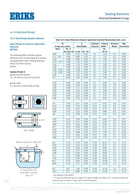
Sealing Elements<strong>Technical</strong> <strong>Handbook</strong> O-<strong>ring</strong>s12. O-<strong>ring</strong> Gland Design12 E. Gland Design Dynamic HydraulicGland Design for Dynamic ApplicationHydraulicMETRICThe following table indicates groovedimensions for reciprocating and oscillatingapplications when sealing hydraulicfluids and other viscousliquids.Surface Finish Xgroove top and bottom :X = 16 micro inches (0.4 µm Ra)groove sides:X = 32 micro inches (0.8 µm Ra)Table 3.D-1 Gland Dimensions Dynamic Application-Industrial Reciprocating Seals, m e t r i cW E S Diametr. F Groove R Groove Max.O-<strong>ring</strong> cross section Gland Depth Clearance Width ** Radius EccentricityDiam. Tol. +/- Tol.ISO 3601-1B in mm Tol. -0/+ -0/+130,90 0,08 0,72 0,02 0,1 1,20 0,2 0,051,0 - 1,02 0,08 0,80 0,02 0,1 1,35 0,2 0,051,20 0,08 0,96 0,02 0,1 1,60 0,2 0,051,25 - 1,27 0,08 1,00 0,02 0,1 1,70 0,2 0,051,42 0,08 1,13 0,02 0,1 1,90 0,2 0,051,50 0,08 1,20 0,02 0,1 2,00 0,2 0,051,60 - 1,63 0,08 1,28 0,03 0,1 2,10 0,2 0,051,78 - 1,80 0,08 1,42 0,03 0,1 2,40 0,2 0,051,90 0,08 1,52 0,03 0,1 2,50 0,2 0,052,0 0,08 1,60 0,04 0,1 2,65 0,2 0,052,20 0,09 1,89 0,04 0,1 3,00 0,2 0,052,40 0,09 2,06 0,04 0,1 3,25 0,2 0,052,46 0,09 2,11 0,04 0,1 3,35 0,2 0,052,50 0,09 2,15 0,04 0,1 3,40 0,2 0,052,65 0,09 2,25 0,04 0,1 3,55 0,2 0,052,70 0,09 2,32 0,04 0,1 3,70 0,2 0,052,95 0,09 2,53 0,04 0,1 4,00 0,5 0,053,0 0,09 2,61 0,04 0,15 4,05 0,5 0,073,15 0,09 2,74 0,05 0,15 4,25 0,5 0,073,55 0,10 3,07 0,05 0,15 4,75 0,5 0,073,60 0,10 3,13 0,05 0,15 4,85 0,5 0,074,0 0,10 3,48 0,05 0,15 5,40 0,5 0,07146Fig. 1-33/34Break corners app. R = .005 (0,15)x = surface finish µm R agroove depth is incl. gapFig. 1-274,50 0,10 3,99 0,05 0,15 6,00 0,5 0,074,70 0,13 4,17 0,05 0,15 6,30 0,5 0,074,80 0,13 4,26 0,05 0,15 6,40 0,5 0,075,0 0,13 4,44 0,05 0,15 6,70 0,7 0,105,30 0,13 4,73 0,05 0,15 7,15 0,7 0,105,50 0,13 4,88 0,05 0,15 7,40 0,7 0,105,70 0,13 5,06 0,05 0,15 7,60 0,7 0,105,80 0,13 5,15 0,05 0,15 7,75 0,7 0,106,0 0,13 5,19 0,05 0,18 8,15 0,7 0,136,40 0,15 5,54 0,05 0,18 8,70 0,7 0,136,50 0,15 5,63 0,05 0,18 8,85 0,7 0,136,90 0,15 5,97 0,05 0,18 9,40 0,7 0,136,99 0,15 6,05 0,05 0,18 9,50 0,7 0,137,0 0,15 6,06 0,05 0,18 9,55 0,7 0,137,50 0,15 6,49 0,05 0,18 10,20 1,0 0,138,0 0,15 6,92 0,05 0,18 10,90 1,0 0,138,40 0,15 7,27 0,05 0,18 11,45 1,0 0,139,0 0,2* 7,92 0,05 0,18 12,10 1,0 0,1310,0 0,2* 8,80 0,05 0,18 13,40 1,0 0,13* Not defined in ISO 3601/1** For groove width with back-up <strong>ring</strong>s for O-<strong>ring</strong>s AS 568A, see table 3.D-2. For groove width withback-up <strong>ring</strong>s for metric O-<strong>ring</strong>s, ask for more information.All the information in this documentation has been compiled with the greatest of care.Despite this we can bear no responsibility whatsoever for any errors present in the documentation. The recommendations are intended as guidelines.www.eriks.info