IB-80000A Non Segregated Phase Bus Duct - Powell Industries, Inc.
IB-80000A Non Segregated Phase Bus Duct - Powell Industries, Inc.
IB-80000A Non Segregated Phase Bus Duct - Powell Industries, Inc.

Create successful ePaper yourself
Turn your PDF publications into a flip-book with our unique Google optimized e-Paper software.
<strong>IB</strong>-<strong>80000A</strong> <strong>Non</strong> <strong>Segregated</strong> <strong>Phase</strong> <strong>Bus</strong> <strong>Duct</strong>600V to 38kV, 1200A to 4000APowered by Safety ®
<strong>Non</strong> <strong>Segregated</strong> <strong>Phase</strong> <strong>Bus</strong> <strong>Duct</strong><strong>IB</strong>-<strong>80000A</strong>Contact Information<strong>Powell</strong> Electrical Systems, <strong>Inc</strong>.www.powellind.com<strong>Powell</strong> Apparatus ServiceE-mail: Info@powellservice.comPO Box 12818, Houston, Texas 77217-2818Tel: 713.944.6900Fax: 713.947.4453Powered by Safety ®
<strong>Non</strong> <strong>Segregated</strong> <strong>Phase</strong> <strong>Bus</strong> <strong>Duct</strong><strong>IB</strong>-<strong>80000A</strong>ContentsI. Introduction ................................................................................................................................................................................ 2II. Safety ............................................................................................................................................................................................. 2III. Description .................................................................................................................................................................. 2IV. Receiving, Unpacking, Handling and Storage ................................................................................................................. 4A) Receiving ...................................................................................................................................................................... 4B) Unpacking .................................................................................................................................................................... 4C) Handling ....................................................................................................................................................................... 4D) Storage .......................................................................................................................................................................... 5V. Installation ................................................................................................................................................................................... 5A) Alignment of Apparatus .......................................................................................................................................... 5B) Installation Checklist ................................................................................................................................................ 6C) Preliminary Steps ....................................................................................................................................................... 6D) Mechanical Installation and Support ................................................................................................................. 7E) Connection of <strong>Bus</strong> Bars ............................................................................................................................................ 9F) Insulation of <strong>Bus</strong> Joints ............................................................................................................................................ 9G) Final Installation Steps ...........................................................................................................................................10VI. Checks Before Energizing .....................................................................................................................................................11VII. Energizing the <strong>Bus</strong> <strong>Duct</strong> .......................................................................................................................................................11VIII. Maintenance .............................................................................................................................................................................12IX. Recommended Renewal Parts ............................................................................................................................................13FiguresFigure 1 Typical Cross Section of <strong>Bus</strong> <strong>Duct</strong> with Polyester Glass <strong>Bus</strong> Supports .................................................... ......3Figure 2 Typical Cross Section of <strong>Bus</strong> <strong>Duct</strong> with Molded Alumina <strong>Bus</strong> Supports ........................................................3Figure 3 Typical Cross Section of <strong>Bus</strong> <strong>Duct</strong> with Porcelain Standoff <strong>Bus</strong> Supports ....................................................4Figure 4 <strong>Bus</strong> <strong>Duct</strong> Section End, Showing Matching Alignment Numbers and Heater Wiring Connections .........7Figure 5 Typical <strong>Bus</strong> <strong>Duct</strong> Wall Section with Vapor Barrier ..............................................................................................7Figure 6 Typical Floor Mounted <strong>Bus</strong> <strong>Duct</strong> Support .............................................................................................................8Figure 7 Typical Hanging <strong>Bus</strong> <strong>Duct</strong> Support ........................................................................................................................9Figure 8 Wrapping of <strong>Bus</strong> Bars ......................................................................................................................................... .... 10Powered by Safety ®i
<strong>Non</strong> <strong>Segregated</strong> <strong>Phase</strong> <strong>Bus</strong> <strong>Duct</strong><strong>IB</strong>-<strong>80000A</strong>!WARNINGTHE EQUIPMENT DESCR<strong>IB</strong>ED IN THIS DOCUMENT CONTAINS HIGHVOLTAGES AND CURRENTS WHICH CAN CAUSE SERIOUS INJURY ORDEATH.THE EQUIPMENT IS DESIGNED FOR USE, INSTALLATION, ANDMAINTENANCE BY KNOWLEDGEABLE USERS OF SUCH EQUIPMENTHAVING EXPERIENCE AND TRAINING IN THE FIELD OF HIGH VOLTAGEELECTRICITY. THIS DOCUMENT, AND ALL OTHER DOCUMENTATIONSHALL BE FULLY READ, UNDERSTOOD, AND ALL WARNINGS ANDCAUTIONS SHALL BE ABIDED BY.IF THERE ARE ANY DISCREPANCIES OR QUESTIONS, THE USERSHALL CONTACT POWELL ELECTRICAL MANUFACTURING COMPANYIMMEDIATELY AT 1-800-480-7273.!WARNINGBEFORE ANY ADJUSTMENT, SERVICING, PARTS REPLACEMENT, OR ANYOTHER ACT IS PERFORMED REQUIRING PHYSICAL CONTACT WITH THEELECTRICAL WORKING COMPONENTS OR WIRING OF THE EQUIPMENTDESCR<strong>IB</strong>ED IN THIS DOCUMENT, THE POWER SUPPLY MUST BEDISCONNECTED. FAILURE TO FOLLOW THIS WARNING MAY RESULT ININJURY OR DEATH.Powered by Safety ® 1
2 Powered by Safety ®<strong>Non</strong> <strong>Segregated</strong> <strong>Phase</strong> <strong>Bus</strong> <strong>Duct</strong> <strong>IB</strong>-<strong>80000A</strong>! CAUTIONBEFORE ANY ADJUSTMENT, SERVICING, PARTS REPLACEMENT, OR ANY OTHER ACT ISPERFORMED REQUIRING PHYSICAL CONTACT WITH THE ELECTRICAL WORKING COMPONENTSOR WIRING OF THIS EQUIPMENT, THE POWER SUPPLY MUST BE DISCONNECTED.I. INTRODUCTION2) Do not work on an energized bus duct.3) Do not climb on, walk on or sit on the busBefore installing the bus duct, study this manualduct. It is not designed to support the weightand the drawings furnished with the bus duct.of a person.Because bus duct is highly variable equipment,custom designed for the particular application, theseinstructions nor the drawings are complete withoutreference to the other. Follow the recommended4) Do not use the bus duct for support of otherequipment. It is not designed to support thisextra weight.procedure for putting into service.5) For the safety of personnel performingThis manual contains:1) Safety Rules.2) A general description of the bus duct.3) Instructions for putting into service.maintenance operations on the bus duct oron connected equipment, all componentsshould be disconnected by means of a visiblebreak and securely grounded.4) Instructions for maintenance.6) See additional safety precautions inthe sections headed “HANDLING” andINSTALLATION”.These instructions do not purport to cover alldetails or variations of bus duct, nor to provide forevery possible contingency or hazard to be metin connection with further information be desiredIII. DESCRIPTIONor should particular problems arise which are not The bus duct covered by these instructions is noncovered sufficiently for the user’s purposes, the segregated phase bus designed, built and tested inmatter should be referred to <strong>Powell</strong>.accordance with ANSI/IEEE StandardC37.23-1987, IEEE Guide for Metal-Enclosed <strong>Bus</strong> andII. SAFETYCalculating Losses in Isolated <strong>Phase</strong> <strong>Bus</strong>. This standarddefines metal-enclosed bus as “An assembly ofconductors with associated connections, joints,The bus duct described in this manual, when in and insulating supports within a grounded metalservice, will be energized by voltages which will cause enclosure. The conductors may be either rigid orsevere injury or death if contacted. To insure the flexible.” It further defines nonsegregated phasesafety of personnel associated with the installation, bus as “One in which all phase conductors are in aoperation and maintenance of bus duct, the following common metal enclosure without barriers betweenrules should be observed:the phases.”1) Only qualified personnel trained in theinstallation, operation and maintenanceof electrical power equipment should beallowed to work on this bus duct.
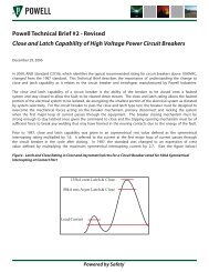
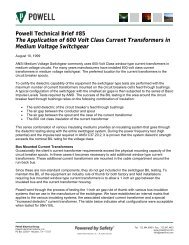
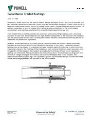
<strong>Non</strong> <strong>Segregated</strong> <strong>Phase</strong> <strong>Bus</strong> <strong>Duct</strong><strong>IB</strong>-<strong>80000A</strong><strong>Bus</strong> duct is normally used to connect two piecesof electrical power equipment, such as two unitsof metal-enclosed switchgear, a transformer anda switchgear unit, a large rotating machine and aswitchgear unit, or a large rotating machine and atransformer. The bus duct may be located eitherindoors or outdoors, or a single run of bus duct maypass from indoors to outdoors one or more times.Standard ratings of bus duct are listed in Table 1.Other ratings are available when required.The standard enclosure of <strong>Powell</strong> bus duct for ratingsless than 3000A continuous current has sides andbottom made of steel, with the top being aluminum.Higher ratings normally have all aluminumenclosures. All aluminum enclosures are available forlower ratings if required.Table 1RatedVoltagekVStandard <strong>Bus</strong> <strong>Duct</strong> RatingsBILkV60HzHipotkVdcHipotkV*0.635 --- 2.2 3.1ContinuousCurrentAmperes1200, 1600, 3000,40004.76 60 19.0 27.0 1200, 2000, 300015.0 95 36.0 50.0 1200, 2000, 300025.8 125 60.0 85.0 1200, 200038.0 150 80.0 --- 1200, 2000polyester laminate, with or without inserts of eithercycloaliphatic epoxy or porcelain. See Figure 1 fora cross section of this style of bus duct. Alternatemethods of support are supports of molded glassreinforcedpolyester (Figure 2) or standoff insulatorsof glass-reinforced polyester, cycloaliphatic epoxy orporcelain (Figure 3). Refer to the drawings providedwith the bus duct for detailed cross sections,including dimensions.Space heaters are furnished in all outdoor bus ductsrated 5kV and above, and may be furnished in otherbus ducts when required. These heaters are designedto minimize condensation in the bus duct by keepingthe air inside the bus duct at a temperature abovethe dew point. Special heaters designed to operateat a low surface temperature are furnished to insure along life for the heater elements. These heaters maybe furnished with thermostatic control on request.Figure 1:C LTypical Cross Section <strong>Bus</strong> <strong>Duct</strong> withPolyester Glass <strong>Bus</strong> SupportsRemovable Top CoverAluminum<strong>Duct</strong> HousingAluminum or SteelCopper <strong>Bus</strong> BarsPolyester Glass<strong>Bus</strong> Support* The presence of the column headed “dc Hipot” does not imply anyrequirement for a dc withstand test on ac equipment. This columnis given as a reference only for those using dc tests and representsvalues believed to be appropriate and approximately equivalent tothe corresponding power frequency withstand test values specifiedfor each class of bus duct.The conductors in <strong>Powell</strong> bus ducts are usually solidrectangular copper bars with full rounded edges,although in higher ratings round or square tubesmay be used. At connections to apparatus bushings,flexible connectors are used to avoid placing unduestrain on the bushings. For bus ducts rated 4.76kVand above, the conductors are insulated. Theconductors in bus ducts rated 635V are normallyuninsulated, but may be insulated on request.The conductors in <strong>Powell</strong> bus duct are usuallysupported by milled slabs of glass-reinforcedFigure 2:Space Heater WireSlots forCondensate FlowTypical Cross Section <strong>Bus</strong> <strong>Duct</strong> with Molded<strong>Bus</strong> SupportsRemovable Top CoverAluminum<strong>Duct</strong> HousingAluminumCopper <strong>Bus</strong> BarsMolded Alumina<strong>Bus</strong> SupportPowered by Safety ® 3
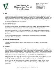
<strong>Non</strong> <strong>Segregated</strong> <strong>Phase</strong> <strong>Bus</strong> <strong>Duct</strong> <strong>IB</strong>-<strong>80000A</strong>Figure 3: Typical Cross Section <strong>Bus</strong> <strong>Duct</strong> withPorcelain Standoff <strong>Bus</strong> SupportsB. UNPACKING1) Carefully unpack all sections of the busRemovable Top CoverAluminum<strong>Duct</strong> HousingAluminum or SteelCopper <strong>Bus</strong> Bars15kV Stand-OffInsulatorStand-Off Bracketduct. To avoid damage to the bus duct,band cutters should be used on all bandingsecuring the packages and nail pullers shouldbe used for unpacking wooden crates.2) Carefully remove any support blocks or othertemporary fasteners which may have beenSpace Heater WireGround <strong>Bus</strong>used for shipping.3) If the bus duct is not to be installedIn addition to the items described in the definitionimmediately, save all packing and wrappingof non segregated phase bus, bus ducts frequentlymaterials for reuse while the bus duct is ininclude other special features such as vapor barriers,storage.fire barriers, or termination sections to matchswitchgear, transformers, or rotating machines. TheC. HANDLINGbus duct or the termination section may include suchitems as removable links in the conductors, currenttransformers, voltage transformers, surge arresters orsurge capacitors, if required by the installation.<strong>Bus</strong> ducts are not self-supporting, but must besupported at installation. Indoor bus ducts arenormally supported by hanging from the ceiling, butmay also be supported from floors or walls or fromother pieces of equipment, such as switchgear units.Outdoor bus ducts are normally supported from theground. Supports for bus duct sections are normallyfurnished by the user or the installing contractor, butTo help avoid personal injury and equipment damageduring handling, and to facilitate moving the busduct sections and fittings at the job site, follow theseguidelines:1) <strong>Bus</strong> duct sections are quite heavy, weighingup to several hundred pounds per section. Toavoid personal injury, do not attempt to lift,carry, or otherwise move bus duct sections byhand. Use appropriate mechanical means tohandle bus duct. Be sure that the handlingequipment used is capable of safely handlingthe bus duct sections.may be included with the bus duct when specified.See the section headed “INSTALLATION” for further2) Handle bus duct with care to avoid damageinformation on bus duct supports.to internal components and the enclosureand its finish. Avoid subjecting bus duct totwisting, denting, impact, and in general,IV. RECEIVING, UNPACKINGrough handling. Avoiding damage toprotruding objects such as flanges, drain andHANDLING AND STORAGEvent fittings, heater boxes, etc.A. RECEIVING3) When setting bus duct sections on theground or on a floor, the main body of theWhen the bus duct is received, unpack it sufficientlyduct enclosure should be set on a support toto inspect it for concealed damage and to determineprotect flanges and other protruding objects.that the shipment is complete and correct. If damageA short length of 2”x4” or 4”x4” lumber makesis found or suspected, file claims as soon as possiblea good support.with the transportation company, and notify thenearest representative of <strong>Powell</strong>.Powered by Safety ®
<strong>Non</strong> <strong>Segregated</strong> <strong>Phase</strong> <strong>Bus</strong> <strong>Duct</strong><strong>IB</strong>-<strong>80000A</strong>4) Do not drag bus duct sections across the flooror the ground.5) Do not use bus bar ends for lifting bus ductsections or fittings. Lift only the bus ductenclosure, using support means such as slingsor lift truck forks which extend under the fullwidth of the enclosure.6) Keep the bus duct enclosure level whenlifting. Unsecured bus bar may slide out of itsinsulating sleeve or supports if the enclosureis tilted during lifting.7) If a section of bus duct must be liftedvertically, be sure that the bus bars aresecured to the housing to prevent sliding.8) Platform dollies provide a simple method ofmoving bus duct on one floor level if there islittle or no incline. Balance the load carefullyand secure it to the dolly.9) If a crane is used to install bus duct, use nylonstraps and distribute or balance the weight ofeach lift. If cables are used, spreaders shouldbe used to avoid damage to metal housing.Lifting straps and cables must have sufficientstrength to hold the load of the section to belifted.10) If a fork or similar hoist is used, properlyposition the bus duct enclosure on the forksto distribute its weight. Secure the load tothe forks while lifting.D. STORAGE1) To prevent condensation, bus duct sectionsand fittings which are not to be installed andenergized immediately should be stored in aclean dry space having a moderate, uniformtemperature, in the range of 40˚-100˚F.Preferably, bus duct sections should be storedin a heated building having adequate aircirculation, and protected from dirt, fumes,water, and physical damage.2) <strong>Bus</strong> duct sections should not be storedoutdoors because of possible moisturedamage. If bus duct must be stored outdoors,it must be securely covered for protectionfrom weather and dirt. Temporary electricalheating should be installed beneath the coverto prevent condensation. At least 3 wattsper cubic foot is adequate for the averageenvironment. If internal bus duct heaters areused during storage, remove all combustiblematerials from the area of the heaters beforeenergizing.3) Weatherproof bus duct must be treatedexactly the same as indoor bus duct untilafter it is installed. It is not weatherproof untilcompletely and properly installed.4) Do not expose bus duct sections and fittingsto high concentrations of hydrocarbon-basedsolvent vapors. Such vapors may damage ordestroy the bus bar insulation.V. INSTALLATIONA. ALIGNMENT OF APPARATUSBefore installing a run of bus duct, carefully check thelocation of the apparatus to be connected by the busduct. The relative location of the two ends of the busduct run must be as shown on the bus duct layoutdrawing for the bus duct to fit properly. For a typicalbus duct run of about 20 feet, the relative locationsof the two end connections should not deviate fromthe bus duct arrangement drawing by more than ¼”in any direction, or by more than ” total. Location ofwalls which are penetrated by a bus duct run shouldalso be checked. The center lines of the wall cutoutshould not deviate from the center lines of the busduct run by more than ½”, and the location of thewall along the length of the bus duct run shouldnot deviate from its position on the bus duct layoutdrawing by more than ¼ of the thickness of the wall,to insure that vapor barriers fall within the thicknessof the wall, where they will be effective.Powered by Safety ® 5
6 Powered by Safety ®<strong>Non</strong> <strong>Segregated</strong> <strong>Phase</strong> <strong>Bus</strong> <strong>Duct</strong> <strong>IB</strong>-<strong>80000A</strong>If the terminal points of the bus duct are not alignedwithin these limits, corrective action must be taken.If at all possible, the apparatus to which the bus ductconnects should be moved so that the alignment iswithin limits. If this is not possible, contact <strong>Powell</strong>6) Align the duct sections and bolt theenclosures together. Be sure all outdoorsections are bolted with stainless steelhardware, and that there are gaskets at alloutdoor enclosure joints.with all necessary dimensions, so that correctiveaction can be taken.7) Attach and adjust all bus duct supports,levelling and plumbing the duct as necessary.Do not count on flexible connectors at theSee §D for additional information.terminations of a bus duct run to correctmisalignment problems beyond the limits given8) Remove the covers from the duct if notabove. Flexible connectors are furnished to limitpreviously removed.stress on apparatus terminations caused by thermal 9) Loosely connect all bus joints, installingexpansion and vibration, and to correct very minorhardware, splice plates and flexible(
<strong>Non</strong> <strong>Segregated</strong> <strong>Phase</strong> <strong>Bus</strong> <strong>Duct</strong><strong>IB</strong>-<strong>80000A</strong>duct is marked with alignment numbers to allow forrapid matching and aligning of bus duct sections.See figure 4. These alignment numbers are markedon the <strong>Powell</strong> arrangement drawings to show howand where each piece of bus duct should be located.Refer to <strong>Powell</strong> arrangement drawings for the properplacement of bus duct. Care should be taken inlaying out the bus duct that the mating numbersare matched and that the layout matches the <strong>Powell</strong>arrangement drawings.After the duct has been laid out on the ground theaccess covers should be removed. The cover providesneeded support for handling some larger bus ducts,and should not be removed before this stage ofinstallation.Install gaskets on one flange of all mating joints in theoutdoor section of the bus duct, including the flangeon the cover. This gasket is not installed in the factoryin order to prevent damage during shipping andhandling.D. MECHANICAL INSTALLATION AND SUPPORTAfter the covers are removed the bus duct shouldbe lifted into place a section at a time. Each sectionshould be properly supported during assembly andattached to the next piece by finger tightening theflange bolts. Connections of bus bars should not bemade at this time.Wall penetration sections containing fire barriersor vapor barriers must be positioned so that thebarrier is within the thickness of the wall it passesthrough. See Figure 5. While the wall section may besupported temporarily by the lower part of the wallflange, do not complete the installation of the wallflange at this time.Figure 5:Typical <strong>Bus</strong> <strong>Duct</strong> Wall Section with VaporBarrierWallSeam Welded<strong>Duct</strong> BodyRTV Silicone SealFigure 4:<strong>Bus</strong> <strong>Duct</strong> Section End, Showing MatchingAlignment Numbers and Heater WiringConnectionsRecommended WallCutout - Overall FlangeDimension +1" On All(4) SidesFlange DimensionFrom <strong>Bus</strong> <strong>Duct</strong>Cross-SectionDetail1/4" Thick Polyester Glass<strong>Bus</strong> Bars20Top View<strong>Bus</strong> duct runs are not self-supporting, and mustbe properly supported for trouble-free service.Some bus duct runs, such as those connectingswitchgear lineups located close to each other, maybe completely supported from the apparatus at theends of the run. Other runs of bus duct, even thoughreceiving some support from apparatus at the endsof the run and from wall penetrations, will requireadditional support.All bus duct should be supported every ten feet withno more than two joints between supports. Extrasupports should be used at all corners. Apparatusat the ends of bus duct runs should be checked tobe sure that it can carry the weight of the attachedPowered by Safety ® 7
<strong>Non</strong> <strong>Segregated</strong> <strong>Phase</strong> <strong>Bus</strong> <strong>Duct</strong> <strong>IB</strong>-<strong>80000A</strong>bus duct without difficulty. If it cannot, the busduct should be supported separately as close to thetermination as possible.supported from below. <strong>Powell</strong> bus ducts are normallywill be furnished with angle clips attached to thebus duct body for the attachment of supports. Thelocation of these clips will show on the bus ductSupports for indoor bus ducts may be either from thelayout drawing, and may be adjusted to meet thefloor or from above. Outdoor bus ducts are normallyuser’s needs on request. Unless required by thepurchase order, <strong>Powell</strong> will not supply the supports,so they must be supplied by either the user or theinstalling contractor. A typical design for a supportfrom beneath the bus duct is shown in Figure 6 anda typical design for a hanging support is shown inFigure 7.Figure 6: Typical Floor Mounted <strong>Bus</strong><strong>Duct</strong> SupportX = <strong>Bus</strong> <strong>Duct</strong> Width + 4"X10.875 Dia.Hole (4)<strong>Bus</strong> <strong>Duct</strong>10'B'1-1/21.6251-5/8 x 4 Channel1-1/22 x 2 x 3/16 AngleDetail 'A'N.T.SY = Height asRequired4 x 4 x 3/16Steel TubeAngle Clip(Furnished with <strong>Bus</strong> <strong>Duct</strong>3/8-16 x 1-1/41/2" Steel PlateHH BoltSee Detail 'A'Pier or FootingDetail 'B'(Furnished by Installer)N.T.SPowered by Safety ®
<strong>Non</strong> <strong>Segregated</strong> <strong>Phase</strong> <strong>Bus</strong> <strong>Duct</strong><strong>IB</strong>-<strong>80000A</strong>Figure 7:Typical Hanging <strong>Bus</strong> <strong>Duct</strong> Support3/8" Steel Rod(Furnished by Installer)E. CONNECTION OF BUS BARSC LYSupport MemberAttached toBuilding Structure"Y" Dimension VariesDepending on <strong>Bus</strong> <strong>Duct</strong>Elevation3/8" Nut, Lockwasher & FlatwasherBoth Sides (Furnished by Installer)Support Angle Bolted to <strong>Bus</strong> <strong>Duct</strong>(Furnished with <strong>Bus</strong> <strong>Duct</strong>)Before beginning the assembly of bus barconnections, clean all contact surfaces and removeany contamination or corrosion. Wipe surface clean.Do not use sandpaper or any abrasive on the platedsurface. Avoid handling of cleaned surface as muchas possible. If a hydrocarbon-based solvent is usedin the cleaning process, be sure that it does notcome into contact with the bus bar insulation. Thesesolvents may damage or destroy the insulation.Align the bus bar ends of adjoining sections andverify proper phase alignment. After the entire busduct is properly positioned and aligned the bus barsshould be loosely bolted together with the spliceplates and hardware provided. To insure that thejoints are made up without unnecessary strain, it maybe necessary in some cases to loosen the joints andsupport insulators on either side of the joint beingmade.Take special care with the installation of theconnections to other apparatus at the ends of thebus duct run. These connections frequently makeuse of flexible connectors. Refer to the drawingsfurnished with the bus duct for the proper installationof the flexible connectors. Do not use these flexibleconnectors are furnished to limit stress caused bythermal expansion and vibration on apparatusterminations, and to correct very minor (
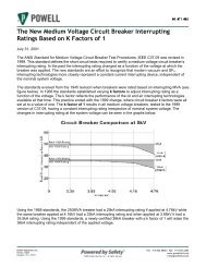
10 Powered by Safety ®<strong>Non</strong> <strong>Segregated</strong> <strong>Phase</strong> <strong>Bus</strong> <strong>Duct</strong> <strong>IB</strong>-<strong>80000A</strong>Wrap joint with Scotch Super 33+ black G. FINAL INSTALLATION STEPSinsulating tape, 1 inch wide, maintainingtension on the tape while wrapping. WhereSpace heaters are provided as standard equipmentthere are sharp angles, apply additional layersin all outdoor bus ducts rated 5kV or higher, and into obtain equivalent of the insulation on theother bus ducts when requested by the customer. Itflat surfaces. Use two layers, ⅔ lap requiresis recommended that the heaters be energized atthree turns around the bus bar in one widthall times. No switch or thermostat is provided in theof tape. See Figure 8. Finish taping with oneheater circuit unless specified.layer, ½ lap, of Scotch 35 red insulating tape. Heaters providing 250 watts of heat are furnished foreach 10 feet of bus duct. <strong>Powell</strong> space heater wiringNote: The package of Scotch Super 33+ tape, as part of its ULlisting information, includes the phrase “Suitable for use at is a braid covered copper wire. Space heater wiresnot more than 600V”. This is the UL listed voltage rating for should be connected at shipping breaks after the busa single layer of this tape. When applied as described in thepreceding paragraph, this tape is suitable for use at 5kV orduct is in place and the assembly bolts have been15kV, depending on the number of layers applied.properly tightened. See Figure 4 for a view of properwiring.Figure 8: Wrapping of <strong>Bus</strong> Bars1/3"1/3"1/3""A"For 15kV: 3 Layers, 2/3 Lap (9 thicknesses of Tape)For 5kV: 2 Layers, 2/3 Lap (6 thicknesses of Tape)View at "A"
<strong>Non</strong> <strong>Segregated</strong> <strong>Phase</strong> <strong>Bus</strong> <strong>Duct</strong><strong>IB</strong>-<strong>80000A</strong>A power supply of the proper voltage and capacitymust be connected to the space heater circuits.Refer to the drawings supplied with the bus duct todetermine the proper power supply and connectionpoint. If the bus duct is connected to <strong>Powell</strong>switchgear, the space heater supply may be providedin the switchgear.The final installation step is to replace the bus ductcovers and tighten all hardware used to secure thesecovers.VI.CHECKS BEFORE ENERGIZINGBefore energizing the bus duct for the first time, thereare several checks that should be made. To performthese checks, the bus duct conductors must beisolated from the remainder of the electrical system.If disconnect switches or circuit breakers are availableto isolate the bus duct run, open these devices. Ifthere are no disconnecting devices available, unboltthe last connecting link at the end of the bus ductrun.First, check the phasing of the bus duct run fromend to end to insure that the connected apparatusis properly phased. This phasing check can be madewith a bell set, a buzzer, or an ohmmeter. Checkeach phase for continuity, and to be sure it is notconnected to any other phase or to ground.The other major check to be made before energizingis an insulation resistance test. Use an insulationresistance tester (“Megger”) rated at least 500V.Check each phase by connecting the other twophases to the grounded enclosure and measuringbetween the phase under test and the enclosure.Because insulation resistance is a function of thelength of a bus duct, the number of bus supports,the number of conductors per phase, and otherfactors, there is not a fixed value of insulationresistance which is always acceptable. For a new, dryinstallation, any resistance less than one megohm perkV of rated voltage should be questioned. Recordthe values obtained from this test for future use inthe maintenance of the bus duct. See Section VIII,“MAINTENANCE”, for further information.If it is desired to perform a power frequencywithstand test (ac “hipot”) on the bus ductconductors, the test voltage should not exceed 75%of the 60Hz hipot voltage given in Table I for the classof bus duct being tested. DC hipot testing is notrecommended for bus ducts, but if it is required, thetest voltage should not exceed 75% of the dc hipotvoltage given in Table I for the class of bus duct beingtested.If the bus duct is equipped with heaters, the heatersand their wiring should be checked for insulationresistance to ground. Disconnect the power sourcefrom the heater circuit and remove any deliberategrounds on the heater wiring. Connect all conductorsof the heater circuit together and use an insulationresistance tester rated 500V to test between theconductors and ground.Reconnect the heater circuit and energize it fromthe proper power source. Check that all heatersare operating. This may be done by calculating theexpected heater current from the heater circuitsshown on the bus duct drawings and checking thecurrent with a hook-on ammeter or other appropriatetest instrument. Heater operation may also bechecked by feeling near the heater location to notewhether or not it is producing heat.CAUTIONDO NOT TOUCH THE HEATER ELEMENTS.SEVERE BURNS MAY RESULT FROM DIRECTCONTACT WITH AN ENERGIZED HEATER.Once these checks have been made successfully,reconnect and reinsulate any connections that weredisconnected for the checks, and replace any coversremoved. The bus duct should now be ready forenergizing.VII.ENERGIZING THE BUS DUCTThere should be no load on the bus duct when it isenergized. Since bus duct typically extends betweentwo pieces of electrical apparatus, care should betaken to see that all devices fed from the bus duct areswitched to the “OFF” position before energizing thebus duct.Powered by Safety ® 11
12 Powered by Safety ®<strong>Non</strong> <strong>Segregated</strong> <strong>Phase</strong> <strong>Bus</strong> <strong>Duct</strong> <strong>IB</strong>-<strong>80000A</strong>CAUTIONWARNINGBUS DUCTS ARE COMPONENTS OF HIGH CONTACT WITH ENERGIZED CONDUCTORS INPOWER ELECTRICAL SYSTEMS. OPERATION BUS DUCTS MAY LEAD TO PROPERTY DAMAGE,OF ELECTRICAL POWER SYSTEMS SHOULDBE DONE ONLY BY EXPERIENCED PERSONNELQUALIFIED IN THE OPERATION OF SUCHSYSTEMS.SEVERE INJURY OR DEATH. BEFORE REMOVING ANYCOVERS TO SERVICE BUS DUCT, DE-ENERGIZE THEBUS DUCT, OPEN SWITCHING DEVICES AT BOTHENDS OF THE BUS DUCT RUN, AND GROUND THESOURCE CONDUCTORS.Be sure that overcurrent protective devices on thesource side of the bus duct are in place and operatingproperly before energizing the bus duct.Remove the covers from the bus duct and examinethe interior for any moisture or signs of previouswetness. Replace or thoroughly dry and clean anyEnergize the bus duct by closing the switching devicewhich feeds it. Check along the length of the busduct to be sure no abnormal operating conditions areevident. The bus duct is now ready to be loaded byclosing switching devices feeding loads through thebus duct.<strong>Bus</strong> duct, when operating properly, may have amoderate 60Hz hum. Excessive noise may be anindication of hardware that has not been tightened orof metal parts that have been improperly assembled.Occurrence of sparking at any point along the busduct is not a normal condition. The bus duct shouldbe de-energized until the cause of the sparking hasbeen corrected.VIII. MAINTENANCEContact <strong>Powell</strong> for assistance in performingmaintenance or setting up a maintenance program.insulating material which is damp or wet or showsaccumulation of deposited material from previouswetting. For indoor bus duct, eliminate the source ofany dripping onto the bus duct and any other sourceof moisture. For outdoor bus duct, seal off any cracksor openings which have allowed moisture to enterthe bus duct or its connection boxes.Thoroughly clean any accumulation of dust anddirt by using a brush, vacuum cleaner, or clean lintfreerags. If the main bus bars are insulated andforeign material cannot be removed by dusting orwiping with a dry rag, only denatured alcohol orisopropyl alcohol should be used as a solvent toremove materials from the insulation surface. Donot use commercial cleaners or solvents to cleanbus insulation. These materials may destroy theinsulating sleeving.Carefully inspect all visible electrical jointsand terminals. Check tightness of hardware inInspect bus duct in normal service once each year or accordance with Table II. If joints or terminationsafter any severe electrical fault. <strong>Bus</strong> ducts operating appear to be badly discolored, corroded or pitted,in severe environments, such as excessive dust, or show evidence of having been subjected to highsalt spray, chemical vapors, etc., may require more temperatures, the parts should be disassembledfrequent inspection. <strong>Bus</strong> ducts operating in clean, dry, and replaced or cleaned. The plated surface can beindoor locations may need inspection less frequently. cleaned with a good grade of silver polish. Take carenot to remove plating on aluminum or copper partsin joints or terminations. Damaged aluminum orcopper parts should be replaced.Check the insulation resistance prior to re-energizingthe bus duct, using the insulation resistance testdescribed in Section VI. Keep a permanent record ofresistance readings. If readings decrease appreciablywith time, deterioration is taking place. If this
<strong>Non</strong> <strong>Segregated</strong> <strong>Phase</strong> <strong>Bus</strong> <strong>Duct</strong><strong>IB</strong>-<strong>80000A</strong>occurs, find and correct the cause of the insulationdeterioration before re-energizing the bus duct.If the bus duct is equipped with heaters, check themfor proper operation as described in Section VI.Replace any heaters that are not functioning properly.The heaters used in bus duct are long life, low surfacetemperature heaters. Replace them only with heatersof the same rating and catalog number.Replace the covers and secure them properly. Reenergizethe bus duct, observing the precautionsgiven in Section VII.IX.RECOMMENDED RENEWALPARTS<strong>Bus</strong> duct enclosures, conductors and insulationsystems do not include any parts that are normalsubject to wear or that would normally requirereplacement during the useful life of the bus duct.If routine maintenance reveals parts that requirereplacement, they should be ordered at that time.Order any necessary parts from <strong>Powell</strong>. Identify thebus duct for which parts are required by the <strong>Powell</strong>work order on which it was furnished. The order mustbe accompanied by a full description of the partor parts needed. If possible, include a copy of the<strong>Powell</strong> arrangement drawing for the bus duct withthe required parts identified. If this is not possible,a sketch or photograph of the required part shouldaccompany the order.If the bus duct is equipped with heaters, <strong>Powell</strong>recommends keeping spare heaters in stock. Auser should stock about 10% of the total number ofheaters used in his bus ducts. These heaters shouldalso be ordered from <strong>Powell</strong>. The catalog numberof the heater and the number of the <strong>Powell</strong> workorder on which the bus duct was furnished shouldaccompany the order.Powered by Safety ® 13
<strong>IB</strong>-<strong>80000A</strong><strong>Non</strong> <strong>Segregated</strong><strong>Phase</strong> <strong>Bus</strong> <strong>Duct</strong>June, 2005<strong>Powell</strong> Electrical Systems, <strong>Inc</strong>.<strong>Powell</strong> Electrical ManufacturingPO Box 12818 • Houston, TX • 77217Powered by Safety ®©2005 POWELL INDUSTRIES, INC. • ALL RIGHTS RESERVED.Tel: 713.944.6900 • Fax: 713.947.4453Visit us at www.powellind.comEmail us at info@powellind.com