IB-80000A Non Segregated Phase Bus Duct - Powell Industries, Inc.
IB-80000A Non Segregated Phase Bus Duct - Powell Industries, Inc.
IB-80000A Non Segregated Phase Bus Duct - Powell Industries, Inc.

You also want an ePaper? Increase the reach of your titles
YUMPU automatically turns print PDFs into web optimized ePapers that Google loves.
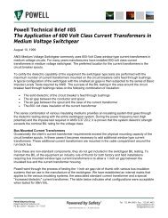
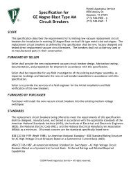
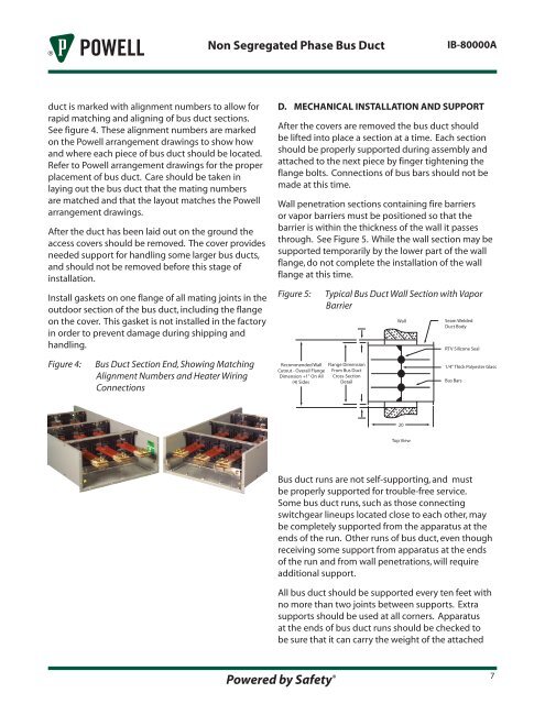
<strong>Non</strong> <strong>Segregated</strong> <strong>Phase</strong> <strong>Bus</strong> <strong>Duct</strong><strong>IB</strong>-<strong>80000A</strong>duct is marked with alignment numbers to allow forrapid matching and aligning of bus duct sections.See figure 4. These alignment numbers are markedon the <strong>Powell</strong> arrangement drawings to show howand where each piece of bus duct should be located.Refer to <strong>Powell</strong> arrangement drawings for the properplacement of bus duct. Care should be taken inlaying out the bus duct that the mating numbersare matched and that the layout matches the <strong>Powell</strong>arrangement drawings.After the duct has been laid out on the ground theaccess covers should be removed. The cover providesneeded support for handling some larger bus ducts,and should not be removed before this stage ofinstallation.Install gaskets on one flange of all mating joints in theoutdoor section of the bus duct, including the flangeon the cover. This gasket is not installed in the factoryin order to prevent damage during shipping andhandling.D. MECHANICAL INSTALLATION AND SUPPORTAfter the covers are removed the bus duct shouldbe lifted into place a section at a time. Each sectionshould be properly supported during assembly andattached to the next piece by finger tightening theflange bolts. Connections of bus bars should not bemade at this time.Wall penetration sections containing fire barriersor vapor barriers must be positioned so that thebarrier is within the thickness of the wall it passesthrough. See Figure 5. While the wall section may besupported temporarily by the lower part of the wallflange, do not complete the installation of the wallflange at this time.Figure 5:Typical <strong>Bus</strong> <strong>Duct</strong> Wall Section with VaporBarrierWallSeam Welded<strong>Duct</strong> BodyRTV Silicone SealFigure 4:<strong>Bus</strong> <strong>Duct</strong> Section End, Showing MatchingAlignment Numbers and Heater WiringConnectionsRecommended WallCutout - Overall FlangeDimension +1" On All(4) SidesFlange DimensionFrom <strong>Bus</strong> <strong>Duct</strong>Cross-SectionDetail1/4" Thick Polyester Glass<strong>Bus</strong> Bars20Top View<strong>Bus</strong> duct runs are not self-supporting, and mustbe properly supported for trouble-free service.Some bus duct runs, such as those connectingswitchgear lineups located close to each other, maybe completely supported from the apparatus at theends of the run. Other runs of bus duct, even thoughreceiving some support from apparatus at the endsof the run and from wall penetrations, will requireadditional support.All bus duct should be supported every ten feet withno more than two joints between supports. Extrasupports should be used at all corners. Apparatusat the ends of bus duct runs should be checked tobe sure that it can carry the weight of the attachedPowered by Safety ® 7