IB-DU1000 Metal-Enclosed Bus - Powell Industries, Inc.
IB-DU1000 Metal-Enclosed Bus - Powell Industries, Inc.
IB-DU1000 Metal-Enclosed Bus - Powell Industries, Inc.

You also want an ePaper? Increase the reach of your titles
YUMPU automatically turns print PDFs into web optimized ePapers that Google loves.
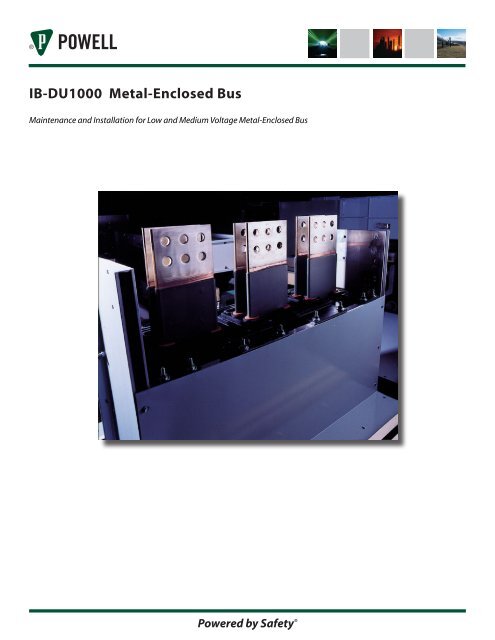
<strong>IB</strong>-<strong>DU1000</strong> <strong>Metal</strong>-<strong>Enclosed</strong> <strong>Bus</strong>Maintenance and Installation for Low and Medium Voltage <strong>Metal</strong>-<strong>Enclosed</strong> <strong>Bus</strong>Powered by Safety ®
<strong>Metal</strong>-<strong>Enclosed</strong> <strong>Bus</strong><strong>IB</strong>-<strong>DU1000</strong>Contact Information<strong>Powell</strong> Electrical Systems, <strong>Inc</strong>.www.powellind.comDelta/UnibusE-mail: Info@deltaunibus.com515 N. Railroad AvenueNorthlake, IL 60164Tel: 708.409.1200Fax: 708.409.1211Powered by Safety ®
<strong>Metal</strong>-<strong>Enclosed</strong> <strong>Bus</strong><strong>IB</strong>-<strong>DU1000</strong>ContentsI. Introduction................................................................................................................................................................................................ 4II. Description................................................................................................................................................................................................. 4A. General.................................................................................................................................................................................................. 4B. Conductors.......................................................................................................................................................................................... 4C. Insulation System.............................................................................................................................................................................. 4D. Enclosure.............................................................................................................................................................................................. 4E. <strong>Bus</strong> Supports....................................................................................................................................................................................... 5III. Receiving and Storage......................................................................................................................................................................... 5A. Shipping............................................................................................................................................................................................... 5B. Receiving.............................................................................................................................................................................................. 5C. Unloading............................................................................................................................................................................................ 5D. Storage.................................................................................................................................................................................................. 7IV. Installation................................................................................................................................................................................................. 8A. Installation Drawings....................................................................................................................................................................... 8B. Erection................................................................................................................................................................................................. 8C. Alignment............................................................................................................................................................................................ 9D. Assembly.............................................................................................................................................................................................. 9E. Field Testing.......................................................................................................................................................................................10V. Operation and Maintenance...........................................................................................................................................................11A. Operation...........................................................................................................................................................................................11B. Maintenance......................................................................................................................................................................................11C. Spare Parts.........................................................................................................................................................................................11D. Field Service......................................................................................................................................................................................11Powered by Safety ®
Powered by Safety ®<strong>Metal</strong>-<strong>Enclosed</strong> <strong>Bus</strong> <strong>IB</strong>-<strong>DU1000</strong>! CautionBefore any adjustment, servicing, parts replacement, or any other act is performedrequiring physical contact with the electrical working components or wiring of thisequipment, the power supply must be disconnected.I. Introductionand power losses. <strong>Bus</strong> conductors may be fullround edge bars, square or round tubes, channels,This manual provides general instruction and informationor tohter configurations. Standard constructionrelated to Delta/Unibus metal-enclosed bus systems.is in compliance with ANSI C37.20 which specifiesRefer to the drawings and information included withan allowable hottest-spot conductor and spliceeach order for specific instructions. All the relevanttemperature rise of 65˚C in a 40˚C ambient. Allinformation provided should be read thoroughlycontact surfaces at joints or terminations arebefore proceeding with any activity to the installation,plated. Contatct surfaces of copper conductors aremaintenance, or operation of the bus system.electrically silver-plated and aluminum conductorsare electrically tin-plated over bronze strike by theAll work must be performed and supervised byAlstan-80A process. Bolted joints in aluminumresponsible personnel who are thoroughly trained andconductors are equipped with conical washers whichknowledgable in all aspects related to the installation,ensure maintenance of contact pressure.maintenance, and operation of bus systems. Theseinstructions are intended to provide only generalC. Insulation Systeminformation related specifically to the installation ofmetal-enclosed bus systems and do not include all theConductor supports may be track-resistant glassprocedures and precautions that must be followed toreinforced polyester blocks, cycloaliphatic epoxyinsure the safety of both personnel and equipment.blocks, or wet process porcelain post insulators.Molded support blocks are ribbed to maximize bothII. Descriptioncreepage distance and mechanical strength. Coronacontrol devices are used to mount the conductorsin the support blocks. These devices also improveA. Generalshort circuit performance by functioning as shockabsorbers for the impact forces encountered duringDelta/Unibus metal-enclosed bus systems are custom high fault currents.designed for each specific application. Segregated,non-segregated, or isolated phase constructions areavailable. A complete line of terminations, horzontaland vertical elbows, horizontal and vertical tee taps,phase transpositions, expansion joints, earthquakeand misalignment joints, wall penetration assemblies,smoke and fire barriers, etc. are utilized to optimizethe design of each bus system.Insulated conductors are normally used on systemsrated 5KV and above. Conductor insulation isavailable for low voltage bus systems. The primaryconductor insulation used is epoxy bonded directlyto the conductor. Conductor splices are usuallyinsulated with molded PVC boots. Terminations maybe insulated with tape or PVC boots.B. ConductorsD. EnclosureCopper or aluminum conductors are selected basedon desired continuous and short circuit currentcapabilities, maximum operating temperatures,Aluminum, painted and/or galvanized steel, andstainless steel housings are available to meet theenvironmental requirements of the installation.
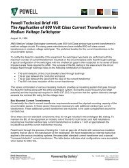
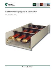
<strong>Metal</strong>-<strong>Enclosed</strong> <strong>Bus</strong><strong>IB</strong>-<strong>DU1000</strong>Highly corrosive resistant aluminum enclosureswhich minimize power losses associated with bothmagnetic and resistance heating are standard.Non-magnetic housings are suggested for mostapplications.Outdoor enclosures are non-ventilated. Screenedbreathers and electric space heaters are used forcondensation control. The electric space heaters maybe either manually or thermostatically controlled.Covers are sloped to shed water and gasketed toinsure water-tightness.Indoor enclosures may be either ventilated or nonventilated.Both the top and bottom covers ofventilated enclosures are Iouvered.The interior surfaces are prepared and protected withone coat of primer. This primer coat also enhancesthe radiation cooling which results in lower operatingtemperatures. All exterior surfaces are prepared,primed, and given a top and final finish coat of indoorANSI-61, outdoor ANSI-70, or outdoor ANSI-24. Othercolors are available upon request.E. <strong>Bus</strong> SupportsA complete line of steel or aluminum structuralsupports is available. Indoor trapeze type, outdoorsingle or double column, wall mounted knee brace,and lattice type trusses are the most frequently used.Outdoor structural steel supports are hot-dippedgalvanized after fabrication or primed and paintedafter fabrication. Indoor supports are primed andpainted to match the bus housing color.III. Receiving and StorageA. ShippingThe bus is shipped in the largest possible factoryassembled sections to facilitate and minimize fieldhandling and assembly. Crating suitable for shipmentvia common carrier motor freight and indoor storageis standard. Special crating suitable for exportshipments or outdoor storage is available. Observemarkings on the crate which may indicate specialprocedures.Auxiliary items such as splice kits, termination kits,insulating materials, bolting hardware, etc. are packedin kits which are clearly identified by purpose andinstallation location. A complete set of installationdrawings, bill of material, and installation manual isshipped with each bus system.B. ReceivingPrior to acceptance of a shipment a completevisual inspection should be performed for anyindications of possible shipping damage. Any suchindications must be noted on the shipping paperswhen accepting delivery. The equipment should beinspected for concealed shipping damage as soonas practicable. If any indication of damage is found,notify the carrier immediately and arrange for hisinspection. The damaged equipment should remainin its crate as received until the carrier’s inspection iscomplete. Photographs should be taken to supportthe claim. Contact your Delta/Unibus representativeimmediately so that corrective action can be initiated.If the terms of the shipment are F.O.B. plant, it is thebuyer’s responsibility to file a claim with the carrier.If the terms are F.O.B. destination, then Delta/Unibuswill file a claim with the carrier. In all cases it is thebuyer’s responsibility to follow proper receivingprocedures.<strong>Inc</strong>oming materials should be carefully checkedagainst the shipping manifest to verify that noshipping losses have occurred and against the billsof material to verify that all items have been received.Shortages should immediately be reported to thecarrier and your Delta/Unibus representative.C. Unloading<strong>Bus</strong> systems can be unloaded utilizing fork-lift trucksor other devices. Lifting slings with a spreaderbar are suggested for safe handling (see Figures1 & 2). Shipping crates must not be stacked. Theequipment must be protected from the weather at alltimes. Tarpaulins can be used to provide temporaryprotection.Powered by Safety ®
Figure 1 <strong>Bus</strong> UnloadingPowered by Safety ®<strong>Metal</strong>-<strong>Enclosed</strong> <strong>Bus</strong> <strong>IB</strong>-<strong>DU1000</strong>
<strong>Metal</strong>-<strong>Enclosed</strong> <strong>Bus</strong><strong>IB</strong>-<strong>DU1000</strong>D. Storage<strong>Bus</strong> systems as shipped must be protected from theweather at all times. For storage periods longer than90 days the bus shall be placed in a weathertight, wellventilated building and protected against vandalism.The floor shall be well drained. The area shall beprovided with uniform heating and temperaturecontrol or its equivalent to prevent condensation andcorrosion.For storage periods of 90 days or less the bus, withproper protection, may be stored in outdoor areasthat are marked and designated for storage. This areais to be well-drained, gravel covered or paved, andreasonably removed from construction areas andtraffic. Items shall be placed on pallets or shoringto allow for air circulation and to avoid trappingwater. A weatherproof covering shall be applied insuch a manner that it protects the equipment yetallow for air-circulation to minimize condensation.The equipment shall be inspected bi-monthly andcorrective action taken as required.The high potential test as described under Maintanenceshould be performed on each section of bus beforeinstallation. This test should also be performedbefore putting the bus into storage if the storageperiod will exceed 90 days. The internal surfaces ofthe bus must be clean and free of condensation ormoisture before attempting a high potential test.Powered by Safety ®
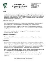
<strong>Metal</strong>-<strong>Enclosed</strong> <strong>Bus</strong> <strong>IB</strong>-<strong>DU1000</strong>IV. InstallationA. Installation DrawingsA set of specific, detailed installation drawings is provided for each bus system. An understanding of theorganization of these drawings is the key to insuring a fast, trouble-free installation. The bus layout drawings andbills of material are the primary drawings which reference and coordinate all the other drawings and procedures.Each section of bus is uniquely identified on the layout drawing by a section number. This identification is markedon each bus section, and the corresponding layout drawings provided with the project can be used to determinethe method of installation of the bus equipment in the field.B. ErectionTypical methods of lifting individual bus sections are illustrated in Figure 2. The use of nylon lifting slings attachedto a spreader bar is a method that enables safe handling and minimizes marring of the paint finish.Figure 2 Lifting and Maneuvering <strong>Bus</strong> SectionThe conductor support system used with insulated conductors is designed to eliminate stresses from thermalexpansion. This is accomplished by not restraining the longitudinal movement of the conductor within the conductorsupport. The conductor in a straight section of bus can be removed by sliding it along the section. Straightsections are supplied with shipping fixtures that retain the conductors in position. CAUTION: THESE FIXTURESMUST NOT BE REMOVED UNTIL INSTALLATION IS COMPLETE OR THE CONDUCTORS HAVE BEEN SAFELY SECURED!!! Powered by Safety ®
<strong>Metal</strong>-<strong>Enclosed</strong> <strong>Bus</strong><strong>IB</strong>-<strong>DU1000</strong>C. AlignmentThe entire run of bus duct should be installed andadjusted at all terminal equipment BEFORE finaltorquing and insulation of bus conductor joints.Adjustments to obtain proper alignment should bedistributed evenly throughout the bus system atevery splice. Normally it is not required but a smallamount of additional adjustment can be obtained byrepositioning end flanges.D. AssemblyInstallation drawings contain the construction andassembly details of standard components.It is important that assemblies be correct in allrespects. Small details such as the position andorientation of spacers and bolting hardware must beobserved. Proper torque procedures help insure atrouble free installation and service life.The contact surfaces of all electrical joints areeither silver or tin plated. The use of electrical jointcompounds is neither required nor recommended.Contact surfaces should be cleaned before assembly.A mild non-metallic abrasive may be used to loosendirt or other contaminants.Each assembly should be cleaned and inspectedas it is completed. Any shipping fixtures must beremoved. SEE THE CAUTION REGARDING STRAIGHTSECTIONS UNDER THE SECTION ON “ERECTION”. Theshipping fixture used on misalignment and vibrationcollars should not be removed until these sections areinstalled or protected from damage.The components necessary to complete theinstallation at each bus end (or splice) have beenshipped in separate identified packages.The bus housings must be properly grounded.Since the type and number of facilities required toestablish adequate grounding can vary considerablyfor different situations, the responsibility for thedesign, installation, & verification of the ground cannot be assumed by Delta/Unibus. Ground pads, withor without cable lugs, can be provided on the bushousings at convenient locations for connectionto station ground. The bus housing can be used toestablish ground continuity in many applications. Itis important that the housing splice plates whichare designed to provide a low resistance connectionbetween adjacent bus sections be properly installed.A continuous insulated or multigrounded copperor aluminum ground bar is also an available option.Flexible ground continuity connections which areprovided at bus expansion joints should be inspectedfor tightness or damage.After the installation is complete, the bus insulationshould be checked from phase-to-phase and phaseto-groundusing a 1000 volt megger.Control wiring, such as instrument transformersecondary circuits, space heater wiring, thermostatcircuits, etc. are subjected to a factory overpotentialtest to ground of 1500 volts, 60 HZ, for one (1) minute.This test should be repeated on the completedinstallation.Perform the AC high potential test as described underField Testing.The entire bus system should be carefully examinedfor any indication of physical damage. Touch up paintshould be applied to any finish surfaces which havebeen damaged. Avoid excessive accumulation oftouch up paint on breathers. Verify that painting hasnot clogged any breathers.It is important that during installation all thenecessary actions are taken to protect the bus fromthe weather and the abnormal entry of dirt or othercontaminants. The space heaters should be put intooperation as soon as practicable.Powered by Safety ®
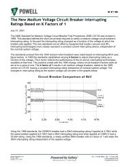
10 Powered by Safety ®<strong>Metal</strong>-<strong>Enclosed</strong> <strong>Bus</strong> <strong>IB</strong>-<strong>DU1000</strong>E. Field TestingA one minute AC high potential test can be performed at 75% of the factory test voltage indicated on the test tagshipped attached to each section of bus. This test is in accordance with ANSI C37.23. See Table 1. The test voltageis applied phase-to-phase and phase-to-ground. If an AC test set is not available, a one minute DC test may beused. All internal components of the bus must be CLEAN and DRY before performing the high potential test.Operation of the bus heaters a minimum of 72 hours before performing a high potential test is recommended.Voltage and Insulation Levels<strong>Bus</strong> RatingInsulation Level (kV)Field TestOne Minute WithstandRated MaximumkV (RMS)Power Frequency Withstand(RMS) Dry One MinuteImpulseWithstandACkV-RMSDCkV0.635 2.2 NA 1.65 2.34.76 19.0 60 14.25 20.2515.00 36.0 95 27.00 37.5015.50 50.0 110 37.50 52.5025.80 60.0 125 45.00 63.7538.00 80.0 150 60.00 84.00
<strong>Metal</strong>-<strong>Enclosed</strong> <strong>Bus</strong><strong>IB</strong>-<strong>DU1000</strong>V. Operation and MaintenanceA. OperationThe metal enclosed bus systems described in thismanual are self cooled systems which have nomoving components. A long reliable service life isassured by carefully following the simple installationand maintenance procedures outlined in this manual.The bus should never be energized with the presenceof moisture or heavy contamination on the interiorsurfaces of the bus. The bus heaters should beoperated a minimum of 72 hours as noted underMAINTENANCE before energizing a bus that has beenout of service for a period of time. The bus heatersmust remain operational any time the bus is in serviceand the possibility of condensation exists.All covers must be securely in position at all timesduring the operation of the bus. Any dented ordamaged housings must be carefully inspected andcorrective action taken before energizing the bus.The bus system is not intended to be a walkway andthis type of activity must be avoided.B. MaintenanceThe Delta/Unibus metal enclosed bus systemhas been designed to eliminate any componentsthat might require periodic routine lubrication,maintenance, or replacement. An annual inspectionof the bus is recommended. This should include acomplete visual check for damage or deteriorationand an operational test of the space heater system.CAUTION: THE BUS SYSTEM MUST BE DE-ENERGIZEDDURING THE REMOVAL OR INSTALLATION OFHEATERS. Screened or filtered breathers shouldbe inspected and cleaned at periodic intervalsdetermined by existing site conditions. Theinsulation should be inspected and cleaned asrequired. Isopropyl alcohol is a suitable solvent thatis recommended. Particular care should be takento avoid the application of any harsh solvents. Theinside surfaces of the housing should be wiped toremove any loose contamination. A vacuum cleanermay be used to facilitate the removal of looseparticles.Field experience has verified that re-torquing ofproperly installed conductor connecting hardwareis not required on a routine basis. Connections thatare suspect should be inspected and re-torqued asrequired.New gasketing is recommended when reinstallingcovers that have been removed.C. Spare PartsThe Delta/Unibus metal enclosed bus system hasbeen designed to eliminate any components thatmight require periodic routine replacement. Thereare no moving parts. Accordingly it is not necessaryfor users to maintain a stock of spare parts.The procedures described under MAINTENANCEmay result in the need for some miscellaneousmaterials such as gasketing, cover mountinghardware, insulating materials, and touch up paint.The availability of these materials can facilitate thecompletion of preventative maintenance inspections.D. Field ServiceContact either your Delta/Unibus sales representativeor the Delta/Unibus plant for further assistance.Trained field service engineers are available toprovide on-site assistance when desired.Delta/Unibus cannot be responsible for anymodifications made to any bus system without itsexpress written authorization.Powered by Safety ® 11
<strong>IB</strong>-<strong>DU1000</strong><strong>Metal</strong>-<strong>Enclosed</strong> <strong>Bus</strong>July, 2006<strong>Powell</strong> Electrical Systems, <strong>Inc</strong>.Delta/Unibus515 N. Railroad Ave. • Northlake, Il • 60164Powered by Safety ®©2005 <strong>Powell</strong> <strong>Industries</strong>, <strong>Inc</strong>. • All rights reserved.Tel: 709.409.1200 • Fax: 709.409.1211www.powellind.cominfo@deltaunibus.com