Lochinvar - API of NH
Lochinvar - API of NH
Lochinvar - API of NH
- No tags were found...

Create successful ePaper yourself
Turn your PDF publications into a flip-book with our unique Google optimized e-Paper software.
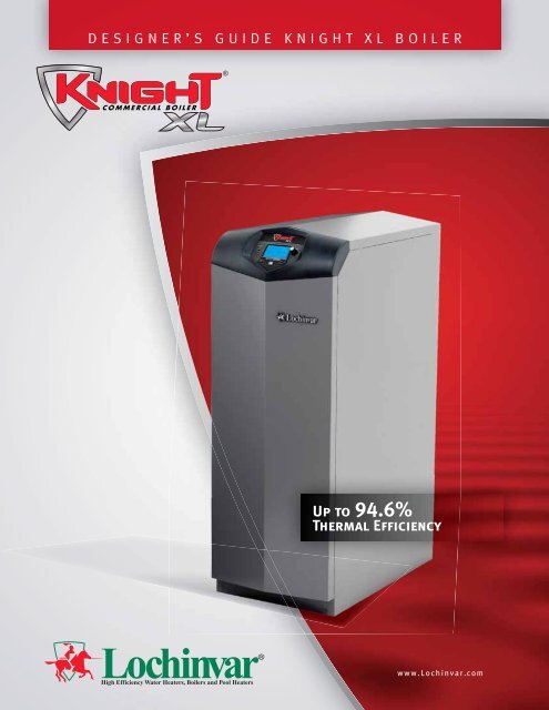
HIGH DESIGNER’S EFFICIENCY GUIDE COMMERCIAL KNIGHT XL BOILERSUp to 94.6%Thermal Efficiencywww.<strong>Lochinvar</strong>.com
Dear Design-Build Contractor / Project Manager / Design Engineer,At <strong>Lochinvar</strong>, we have long recognized the importance <strong>of</strong> innovation to anyproduct or service. Those who share in this business also face the challenge<strong>of</strong> meeting constantly changing needs and energy efficiency demands.The designer’s guide you are now holding has been designed to make it moreconvenient for you to select the perfect <strong>Lochinvar</strong> boiler for your projectsand provide correct specifications for your teams.All information has been organized and presented in a succinct, easy-to-usemanner, so you can use and share information confidently and with minimaleffort.However, it is important to remember that this guide is not intended toreplace our installation manual. Installers should refer to our installationmanual for specific installation instructions and more detail. This guide willmake regular reference to other documents like the Installation & OperationManual that are available on the <strong>Lochinvar</strong> website, www.<strong>Lochinvar</strong>.com.We hope this manual will make your work easier and more productive.Thanks again for specifying the <strong>Lochinvar</strong> family <strong>of</strong> quality standard andcustom-built water heaters and boilers.Sincerely,
Designer’s Guide / Knight XL BoilerAt <strong>Lochinvar</strong>, we know that designing a boiler is hard work.Designing a boiler system is no picnic either. Demands for greater efficiency andelaborate system control have made systems more complex.LOCHINVAR CORPORATION300 MADDOX SIMPSON PKWYLEBANON, TN 37090www.lochinvar.comThis designers guide will break down the system requirements that match the Knight XLboiler to assure safe operation, highly efficient heating and long life.There are five major elements <strong>of</strong> boiler system design:Venting(See page 2)Combustion Air(See page 12)Gas(See page 15)Water(See page 17)Electricity &Controls(See page 23)Plus many other important details:Locations(See page 29 for “Location <strong>of</strong> Unit”)High Altitude Requirements(See page 30 for “High Altitude Applications”)Available Options(See page 30 for “Options”)Suggested Piping Diagram(See page 31, “Appendix Section A”)1
Designer’s Guide / Knight XL BoilerChapter 1 – VentingLOCHINVAR CORPORATION300 MADDOX SIMPSON PKWYLEBANON, TN 37090www.lochinvar.comVenting is <strong>of</strong>ten the most difficult design element for the installation <strong>of</strong> a gas fired appliance, butnot with the Knight XL. The designs are simple and deliver ideal operation. Still, with the venting<strong>of</strong> flue products there are important rules and regulations to follow and the installation bears aresponsibility for human safety.WarningSPILLAGE OF FLUE PRODUCTS AND CARBON MONOXIDE EMISSIONS PRODUCED BY THECOMBUSTION PROCESS CAN CAUSE SEVERE PERSONAL INJURY OR DEATH.<strong>Lochinvar</strong> <strong>of</strong>fers nine different vent configurations on the Knight XL boiler. There are threelayouts or footprints and all are Category IV venting. They are…Direct Vent / SidewallPVC/CPVC with Vent/Air Termination PlatePVC/CPVC with Concentric Vent Kit (400-601 only)PVC/CPVC with two pipe terminationStainless Steel with two pipe terminationDirect Vent / VerticalPVC/CPVC with Concentric Vent Kit (400-601 only)PVC/CPVC with two pipe terminationStainless Steel with two pipe terminationRo<strong>of</strong>top Vent with Air from the Equipment RoomPVC/CPVC vent with Room AirStainless Steel vent with Room AirPart 1Four Important IdeasHere are four important ideas we need to sharebefore we look at each vent configuration.Venting1. Vent Material2. Air Intake Material3. Vent & Air Intake Lengths4. Vent & Air Intake DiametersVENT MATERIALYou have three vent materials to choose from. The vent for a Knight XL can be installed withPVC, CPVC or AL29-4C Stainless Steel. Your choice.You can choose any one <strong>of</strong> the three but we remind you to look around because certainsituations require a specific material. For example, if you are going to install the Knight XL in acloset you MUST use CPVC pipe or Stainless Steel pipe. You cannot use PVC. The logicalreason is, vent pipe temperatures will be higher in a tight, poorly ventilated closet.2
Designer’s Guide / Knight XL BoilerAnother example, some local codes do not allow the use <strong>of</strong> PVC or CPVC for venting flueproducts. In some areas, local code demands the use <strong>of</strong> Stainless Steel vent material.LOCHINVAR CORPORATION300 MADDOX SIMPSON PKWYLEBANON, TN 37090www.lochinvar.comAIR INTAKE MATERIALWith air intake material, you have a wider choice. PVC, CPVC and ABS are allowed. Steel pipe,galvanized or stainless with all joints and seams sealed gas tight. Type “B” double wall ventmaterial with all joints and seams sealed gas tight. With horizontal applications only, you mayeven use Dryer Vent or Sealed Flex Duct.Again, you can choose whatever but we remind you <strong>of</strong> several points. ABS is acceptable for theair intake pipe but not for venting. ABS has been used in the past for venting. In some areas,local codes have been passed that disallow the use <strong>of</strong> ABS for venting.Notice the regular reference to sealing the joints and seams. Whatever air intake material isused, the piping MUST be sealed air tight or gas tight. This is also a requirement <strong>of</strong> the ventpiping. But that is logical. It’s a positive pressure stack carrying flue products so it must besealed from leaks. People <strong>of</strong>ten wonder why we ask to seal the air intake pipe. It’s to keep abalance <strong>of</strong> pressure between the air pipe and the vent pipe. A balance that helps the Knight XLbreathe easier.The use <strong>of</strong> double wall “B” Vent or insulated material for the combustion air intake pipe isrecommended in cold climates to prevent the condensation <strong>of</strong> moisture.VENT LENGTHSThe minimum length for the combustion air intake piping is 12 equivalent feet. The minimumlength for the exhaust is 12 equivalent feet.The maximum length for the combustion air intake piping is 100 equivalent feet. The maximumlength for the exhaust is 100 equivalent feet.When determining equivalent length, add 5 feet for each 90° elbow and 3 feet for each 45° elbow.ImportantTHE APPLIANCE OUTPUT RATE WILL REDUCE BY UP TO 1.5% AT THE MAXIMUM VENT LENGTH.VENT & AIR INTAKE DIAMETERSKnight XL 400 – 501 – 601 / 4” vent and 4” air intake pipe.Knight XL 701 – 801 / 6” vent and 4” air intake pipe.The total lengths <strong>of</strong> each pipe must be these listed diameters. Increasing or decreasing the ventor combustion air piping is not authorized.Part 2Vent / Air Intake ConfigurationsIn the following pages, we will look at each vent / air configuration. For more details andinstallation requirements, please review the Knight XL Installation and Operation manual.3
Designer’s Guide / Knight XL BoilerDIRECT VENT / SIDEWALL - CATEGORY IV VENTINGPVC / CPVC WITH VENT/AIR TERMINATION PLATE.LOCHINVAR CORPORATION300 MADDOX SIMPSON PKWYLEBANON, TN 37090www.lochinvar.comThe exhaust piping terminates out the sidewall. The combustion air pipingterminates out the sidewall.BULLET POINTS This is Category IV venting, positive pressure,condensing stack. All joints and seams must be sealed gastightand may not be common vented. The vent termination plates are provided by<strong>Lochinvar</strong> as standard equipment and all other ventmaterial for this configuration will be obtained locally. Maximum distance – 100 equivalent feet <strong>of</strong> vent. Maximum distance – 100 equivalent feet <strong>of</strong> air intake.4
Designer’s Guide / Knight XL BoilerLOCHINVAR CORPORATION300 MADDOX SIMPSON PKWYLEBANON, TN 37090www.lochinvar.comDIRECT VENT / SIDEWALL - CATEGORY IV VENTINGPVC / CPVC WITH CONCENTRIC VENT KITS (399-600 ONLY).The exhaust piping terminates out the sidewall. The combustion air pipingterminates out the sidewall.BULLET POINTS This is Category IV venting, positive pressure,condensing stack. All joints and seams must be sealed gastightand may not be common vented. The concentric vent termination is provided by<strong>Lochinvar</strong> and all other vent material are obtainedlocally. Maximum distance – 100 equivalent feet <strong>of</strong> vent. Maximum distance – 100 equivalent feet <strong>of</strong> air intake.Model Kit Number Equivalent vent lengthKB(N,L) 400 CVK3007 5 Feet (1.5 m)KB(N,L) 501 CVK3007 30 Feet (9 m)KB(N,L) 601 CVK3007 30 Feet (9 m)5
Designer’s Guide / Knight XL BoilerLOCHINVAR CORPORATION300 MADDOX SIMPSON PKWYLEBANON, TN 37090www.lochinvar.comDIRECT VENT / SIDEWALL - CATEGORY IV VENTINGPVC / CPVC WITH TWO PIPE TERMINATION.The exhaust piping terminates out the sidewall. The combustion air pipingterminates out the sidewall.BULLET POINTS This is Category IV venting, positive pressure,condensing stack. All joints and seams must be sealed gastightand may not be common vented. All the vent material for this configuration areobtained locally, including the terminations. Maximum distance – 100 equivalent feet <strong>of</strong> vent. Maximum distance – 100 equivalent feet <strong>of</strong> air intake.6
Designer’s Guide / Knight XL BoilerLOCHINVAR CORPORATION300 MADDOX SIMPSON PKWYLEBANON, TN 37090www.lochinvar.comDIRECT VENT / SIDEWALL - CATEGORY IV VENTINGSTAINLESS STEEL WITH TWO PIPE TERMINATION.The exhaust piping terminates out the sidewall. The combustion air pipingterminates out the sidewall.BULLET POINTS This is Category IV venting, positive pressure,condensing stack. All joints and seams must be sealed gastightand may not be common vented. The stainless steel vent and air intake terminations areprovided by <strong>Lochinvar</strong> and all other vent material forthis configuration will be obtained locally. Maximum distance – 100 equivalent feet <strong>of</strong> vent. Maximum distance – 100 equivalent feet <strong>of</strong> air intake.ModelKB(N,L) 400 - 601KB(N,L) 701 - 801Kit NumberKIT3136KIT31377
Designer’s Guide / Knight XL BoilerLOCHINVAR CORPORATION300 MADDOX SIMPSON PKWYLEBANON, TN 37090www.lochinvar.comDIRECT VENT / VERTICAL - CATEGORY IV VENTINGPVC / CPVC WITH CONCENTRIC VENT KIT (400-601 ONLY).The exhaust piping terminates through the ro<strong>of</strong>top. The combustion airpiping terminates through the ro<strong>of</strong>top.BULLET POINTS This is Category IV venting, positive pressure,condensing stack. All joints and seams must be sealed gastightand may not be common vented. The concentric vent kit will be provided by<strong>Lochinvar</strong>. All other vent material will be obtained locally. Maximum distance - 100 equivalent feet <strong>of</strong> vent. Maximum distance - 100 equivalent feet <strong>of</strong> air intake.Model Kit Number Equivalent vent lengthKB(N,L) 400 CVK3007 5 Feet (1.5 m)KB(N,L) 501 CVK3007 30 Feet (9 m)KB(N,L) 601 CVK3007 30 Feet (9 m)8
Designer’s Guide / Knight XL BoilerLOCHINVAR CORPORATION300 MADDOX SIMPSON PKWYLEBANON, TN 37090www.lochinvar.comDIRECT VENT / VERTICAL - CATEGORY IV VENTINGPVC / CPVC WITH TWO PIPE TERMINATION.The exhaust piping terminates through the ro<strong>of</strong>top. The combustion airpiping terminates through the ro<strong>of</strong>top.BULLET POINTS This is Category IV venting, positive pressure,condensing stack. All joints and seams must be sealed gastightand may not be common vented. All the vent material for this configuration will beobtained locally, including the terminations. Maximum distance – 100 equivalent feet <strong>of</strong> vent. Maximum distance – 100 equivalent feet <strong>of</strong> air intake.9
Designer’s Guide / Knight XL BoilerLOCHINVAR CORPORATION300 MADDOX SIMPSON PKWYLEBANON, TN 37090www.lochinvar.comDIRECT VENT / VERTICAL - CATEGORY IV VENTINGSTAINLESS STEEL WITH TWO PIPE TERMINATION.The exhaust piping terminates on the ro<strong>of</strong>top. The combustion air pipingterminates through the ro<strong>of</strong>top.BULLET POINTS This is Category IV venting, positive pressure,condensing stack. All joints and seams must be sealed gastightand may not be common vented. All the vent material for this configuration will beobtained locally, including the terminations. Maximum distance – 100 equivalent feet <strong>of</strong> vent. Maximum distance – 100 equivalent feet <strong>of</strong> air intake.10
Designer’s Guide / Knight XL BoilerLOCHINVAR CORPORATION300 MADDOX SIMPSON PKWYLEBANON, TN 37090www.lochinvar.comROOFTOP VENT WITH ROOM AIR OR SIDEWALL AIR - CATEGORY IVPVC / CPVC OR STAINLESS STEEL VENT WITH AIR FROM THEEQUIPMENT ROOM OR FROM DIFFERENT PRESSURE ZONES.The exhaust piping terminates on the ro<strong>of</strong>top. The combustion air isdrawn from the equipment room or from a sidewall termination.PVC/CPVCBULLET POINTS This is Category IV venting, positive pressure,condensing stack. All joints and seams must be sealed gastightand may not be common vented. All the vent material for this configuration will beobtained locally, including the terminations. Maximum distance – 100 equivalent feet <strong>of</strong> vent.Stainless SteelTipIF PLANNING TO USE ROOM AIR, REMEMBER TO ORDER KIT30022, OPTIONAL AIR FILTER BOX.11
Designer’s Guide / Knight XL BoilerChapter 2 – Combustion andVentilation AirLOCHINVAR CORPORATION300 MADDOX SIMPSON PKWYLEBANON, TN 37090www.lochinvar.comEverybody’s gotta breathe. Even boilers need air. Air seems easy enough. You stand in theequipment room and you breathe comfortably, don’t you? Open a door. Open a window. This isa big room. There’ s lots <strong>of</strong> air in here for the boiler. Right?The average person inhales 400 to 500 cubic feet <strong>of</strong> air in a 24 hour period. A one million Btu/hrboiler will draw 226.38 cubic feet <strong>of</strong> air every MINUTE! A 20 by 20 by 8 foot equipment roomholds 3200 cubic feet <strong>of</strong> air. That’s a volume <strong>of</strong> air to last you or me over six days. A half millionBtu/hr Knight XL will consume 6400 cubic feet <strong>of</strong> air in 28 minutes.Therefore, a good, easy flow <strong>of</strong> clean air is 100% necessary for clean, efficient combustion. Withthe Knight XL boiler, we expect the two pipe system illustrated in Chapter 1 will be the mostpopular design used in the field. However, the last two <strong>of</strong>ferings in the venting chapter allowedfor the combustion air to be drawn into the appliance from the equipment room.This chapter explains the methods to ventilate the equipment room to meet the combustionrequirements <strong>of</strong> the Knight XL. This chapter lists several techniques to size the air openings thatwill deliver room air. If there are other appliances in theroom requiring air, their air requirements must beincluding when sizing the air openings.Provisions for combustion and ventilation air must bedesigned and installed in accordance with “Air forCombustion and Ventilation”, <strong>of</strong> the latest edition <strong>of</strong> theNational Fuel Gas Code, ANSI Z223.1, (in Canada, thelatest edition <strong>of</strong> CGA Standard B149 Installation Code forGas Burning Appliances and Equipment) or applicableprovisions <strong>of</strong> the local building codes.AirNEGATIVE PRESSURE IN THE EQUIPMENT ROOMIt is important to NEVER have a negative pressure on the equipment room. Exhaust fans arepopular in equipment rooms to exchange the air. If the exhaust fan pulls air OUT, then a negativepressure occurs in the room. The combustion and ventilation air must be sized to supply all theequipment PLUS the air for the exhaust fan.COMBUSTION AND VENTILATION AIR SIZING CALCULATIONSThe sizing calculations in this section are based on “Free Area”. The louvers or grill used on theair openings must have a net free area equal to or greater than the value derived in thecalculations. The Free Area in a louver or grill is defined as the open, unblocked area. Thelouvers, grills, mesh, blades, all will block a given amount <strong>of</strong> space in the louver’s overalldimension. Consult the louver manufacturer for exact net free area <strong>of</strong> the louver.12
Designer’s Guide / Knight XL BoilerLOCHINVAR CORPORATION300 MADDOX SIMPSON PKWYLEBANON, TN 37090www.lochinvar.com1. COMBUSTION AIR FROM OUTSIDEIf air is taken directly from outside the building with noduct, provide two permanent openings to the equipmentroom:(a) Combustion air opening, with a minimum free area<strong>of</strong> one square inch per 4000 Btu/hr input (5.5 cm² perkW). This opening must be located within 12" (30 cm)<strong>of</strong> the bottom <strong>of</strong> the enclosure.(b) Ventilation air opening, with a minimum free area <strong>of</strong>one square inch per 4000 Btu/hr input (5.5 cm² per kW).This opening must be located within 12" (30 cm) <strong>of</strong> thetop <strong>of</strong> the enclosure.2. COMBUSTION AIR THROUGH DUCTSIf combustion and ventilation air is taken from the outdoors usinga duct to deliver the air to the equipment room, each <strong>of</strong> the twoopenings should be sized based on a minimum free area <strong>of</strong> onesquare inch per 2000 Btu/hr (11 cm² per kW) <strong>of</strong> input.The combustion air duct must be located within 12" (30 cm) <strong>of</strong>the bottom <strong>of</strong> the enclosure and the ventilation duct must belocated must be located within 12" (30 cm) <strong>of</strong> the top <strong>of</strong> theenclosure.3. COMBUSTION AIR FROM INTERIOR SPACEIf air is taken from another interior space, each <strong>of</strong>the two openings specified above should have anet free area <strong>of</strong> one square inch for each 1000Btu/hr (22 cm² per kW) <strong>of</strong> input, but not less than100 square inches (645 cm²).The combustion air opening must be located within12" (30 cm) <strong>of</strong> the bottom <strong>of</strong> the enclosure and theventilation opening must be located must belocated within 12" (30 cm) <strong>of</strong> the top <strong>of</strong> theenclosure13
Designer’s Guide / Knight XL BoilerLOCHINVAR CORPORATION300 MADDOX SIMPSON PKWYLEBANON, TN 37090www.lochinvar.com4. DIRECT OUTSIDE AIR, SINGLE OPENINGIf a single combustion air opening is provided to bringcombustion air in directly from the outdoors, the openingmust be sized based on a minimum free area <strong>of</strong> onesquare inch per 3000 Btu/hr (7 cm² per kW). This openingmust be located within 12" (30 cm) <strong>of</strong> the top <strong>of</strong> theenclosure.CautionTHE COMBUSTION AIR MUST BE FREE OF ANY CONTAMINANTS OR CHEMICAL FUMES. SALTS,REFRIGERANTS AND SOLVENTS INTRODUCED INTO THE COMBUSTION PROCESS WILL RESULT INTHE FORMATION OF CORROSIVE ACIDS THAT WILL DAMAGE THE APPLIANCE AND THE VENT.COMBUSTION AIR FILTERThe Knight XL has an optional air filter box. Locatedon the left side over the combustion air inlet, the airfilter is installed to help ensure clean air is used for thecombustion process. The optional air filter box kit ispart number KIT40002.The filter size is 12" x 12" x 1" (40.6 cm x 30.4 cm x 2.5cm). You can find these commercially available filtersat any home center or plumbing supply store.14
Designer’s Guide / Knight XL BoilerChapter 3 – Gas SupplyLOCHINVAR CORPORATION300 MADDOX SIMPSON PKWYLEBANON, TN 37090www.lochinvar.com<strong>Lochinvar</strong> products are designed with the concept <strong>of</strong> flame control. We develop combustionsystems that tightly control the flow <strong>of</strong> air and gas to deliver a clean and efficient burn. InChapters 1 and 2, we showed the various methods to deliver an ample quantity <strong>of</strong> air to theappliance. In Chapter 3, we discuss delivering a steady and reliable supply <strong>of</strong> gas to theappliance.The key to the gas supply is sizing the gas line properly. The Knight XL will require less than ahalf a pound <strong>of</strong> pressure. The following Sizing Chart is based on less than ½ pound <strong>of</strong> pressureor less than 14 inches <strong>of</strong> pressure. The table is derived from the ANSI Z223.1, the National FuelGas Code.Simply calculate the total linear feet <strong>of</strong> straight gas pipe. Figure each elbow as equal to fivestraight feet <strong>of</strong> pipe. Working down the column that matches your pipe length, find the valueGREATER THAN the total Btu/hr input <strong>of</strong> the boiler or boilers. This will identify the minimumnominal iron pipe size.GAS PIPE SIZING CHARTNominalIronLength <strong>of</strong> Pipe in Straight FeetPipeSize 10 20 30 40 50 60 70 80 90 100 125 150 175 2001" 697 477 384 328 292 267 246 256 210 200 179 164 149 1381 1/4" 1,400 974 789 677 595 543 502 472 441 410 369 333 308 2871 1/2" 2,150 1,500 1,210 1,020 923 830 769 707 666 636 564 513 472 4412" 4,100 2,820 2,260 1,950 1,720 1,560 1,440 1,330 1,250 1,180 1,100 974 871 8202 1/2" 6,460 4,460 3,610 3,100 2,720 2,460 2,310 2,100 2,000 1,900 1,700 1,540 1,400 1,3003" 11,200 7,900 6,400 5,400 4,870 4,410 4,000 3,800 3,540 3,300 3,000 2,720 2,500 2,3404" 23,500 16,100 13,100 11,100 10,000 9,000 8,300 7,690 7,380 6,870 6,150 5,640 5,130 4,720The Knight XL features a Negative-Regulation or Neg-Reg gas combustion system. The gas isintroduced upstream <strong>of</strong> the combustion blower. As the blower draws air in, the negative pressureon the inlet <strong>of</strong> the blower pulls the gas from the gas valve. The gas/air mixture is pushed throughthe blower into the burner. The gas/air mixture filters through the micro-metal burner mesh and isignited by the Spark Igniter.On full fire, a crisp blue flame rises <strong>of</strong>f the surface <strong>of</strong> the burner.As demand decreases, the operating control reduces the blowerspeed. The flame is reduced and it touches the burner surface.The micro-metal fiber burner material is designed to burn infra-redsafely without being damaged by direct contact <strong>of</strong> the flame.Even at this reduced Btu/hr input, the gas/air mixture is balancedto provide clean, efficient combustion.Gas15
Designer’s Guide / Knight XL BoilerLOCHINVAR CORPORATION300 MADDOX SIMPSON PKWYLEBANON, TN 37090www.lochinvar.comThe Knight XL Boiler 400-801 has a 1” gas pipe connection. Logically, the gas pipe size from themeter to the boiler may be larger than the appliance connection.The table below lists the Minimum and Maximum Inlet Gas Pressures.INLET GAS PRESSUREModel NATURAL GAS L.P. GASNumber Max. w.c. Min. w.c. Max. w.c. Min. w.c.Knight XL 400-801 14” 4” 13” 8”L.P. GAS MODELSKnight XL models are typically shipped ready to fire on natural gas. If set to natural gas, theKnight XL boiler may be easily field converted to L.P. gas by either an orifice change or a gasvalve pressure adjustment. See the Knight XL Installation and Operation manual for details.GAS PRESSURE REGULATORS<strong>Lochinvar</strong> recommends the use <strong>of</strong> “Lock-Up Type” gas pressure regulators on the system gassupply. A Lock-Up Type gas pressure regulator features a seat that seals the regulator orificewhen the appliance is <strong>of</strong>f and there is no demand for gas. The seat will seal against the orifice,shutting <strong>of</strong>f the flow <strong>of</strong> gas to the appliance.A standard regulator without a Lock-Up mechanism will allow the system pressure to reach theboiler when it is <strong>of</strong>f. The system pressure can “creep up” pressing against the appliance gas trainwith excessive system pressures. This can damage the components in the gas train.ImportantHIGH PRESSURE GAS REGULATORS MUST BE THE LOCK-UP VARIETY AND MUST BE INSTALLED NOTLESS THAN 10 EQUIVALENT FEET FROM THE BOILER TO PROVIDE AN ADEQUATE VOLUME OF GASFOR SMOOTH IGNITION.16
Designer’s Guide / Knight XL BoilerChapter 4 – WaterLOCHINVAR CORPORATION300 MADDOX SIMPSON PKWYLEBANON, TN 37090www.lochinvar.comWe are no longer designing the gigantic, lumbering, gravity-feed boiler systems <strong>of</strong> ourgrandfathers. Buildings are bigger and more complex. Energy efficiency and “green” buildingdemands have requirements for precise flow, for targeted temperatures, for low water volume andmore. They also demand a water piping system that will not only meet the demands <strong>of</strong> thebuilding but also not damage the boiler.IMPORTANT BULLET POINTS FOR WATER PIPING1. Water ConnectionsKnight 400-501 models have 1 ½” NPT and Knight 601-801 models have 2” NPTthreaded pipe inlet and outlet connections. Installed piping to the boiler must match the1 ½” or 2” diameter, minimum.2. Working PressureThe boiler should not be operated at less than 12 PSIG.3. Minimum & Maximum Water TemperaturesThe minimum inlet water temperature entering the boiler is 0°F (-18°C) with untreadedwater, less with a glycol mix.The maximum outlet water temperature leaving the boiler is 195°F (91°C).4. Flow RateThe boiler works best with a constant flow rate through the heat exchanger. However,recent changes to the SMART SYSTEM control allow the use <strong>of</strong> variable flow pumps.5. Unions and Ball ValvesThe water piping to the boiler should have unions and ball valves at the inlet and outlet<strong>of</strong> the boiler to isolate the boiler for service. Use only full port ball valves.There are three major concepts to consider whendesigning the near boiler piping system. They are…WATER FLOWWATER TEMPERATUREWATER VOLUMEWaterBasically, a boiler or bank <strong>of</strong> boilers has a given range <strong>of</strong> operation under these three concepts.A boiler has a water flow rate range. A boiler has a water temperature range. A boiler has awater volume range. If you design a system that lets the boiler operate within its comfort zone, itlives a long and prosperous life. If the system forces the boiler to operate outside any one <strong>of</strong> thethree comfort zones; the boiler suffers.WATER FLOWThere are an infinite variety <strong>of</strong> system piping which will vary based on the system’s componentsand operational design. Our focus and the focus <strong>of</strong> this guide is to provide the Knight XL boilerwith the flow rate that will allow it to operate at maximum efficiency without damage. To that end,<strong>Lochinvar</strong> requires Primary / Secondary piping.Typically, system flow rates and boiler flow rates need to be controlled separately, that’s why aPrimary / Secondary piping loop is best. The Primary Loop, hereafter referred to as the “SystemLoop” flows water around the building. The Secondary Loop, hereafter referred to as the “BoilerLoop” branches <strong>of</strong>f the system loop to flow water into and out <strong>of</strong> the boiler.17
Designer’s Guide / Knight XL BoilerLOCHINVAR CORPORATION300 MADDOX SIMPSON PKWYLEBANON, TN 37090www.lochinvar.comThe purpose <strong>of</strong> System / Boiler Loop piping is to separate or “decouple” the system flow rate fromthe boiler flow rate.Reference Drawing A1 – Page 32.Reference Drawing A1 – Page ??The System Loop will have its own dedicated “System Circulator”. This circulator will circulatethroughout the building. The Boiler Loop will have its own dedicated “Boiler Circulator”. Thiscirculator will pull from the system to flow into and out <strong>of</strong> the boiler. The Boiler circulator is fieldsupplied and must be sized for the head loss <strong>of</strong> the boiler and related pipe and fittings in theBoiler Loop only.BOILER CIRCULATOR REQUIREMENTSAgain, there will be a minimum <strong>of</strong> two pumps in a System / Boiler Loop. Both pumps areprovided by the installer. The boiler pump must be sized to provide adequate flow through theboiler and the Boiler Loop piping. A Boiler Temperature Rise Chart is provided to assist in properpump selection. This table provides GPM and boiler head-loss at various temperature rises foreach model based on Btu/hr input. Pipe diameter and length are critical to ensure proper flowthrough the boiler. The values listed on the table are based on 20 feet <strong>of</strong> piping, 4 – 90° elbowsand 2 – full port ball valves.CIRCULATOR PUMP SPECIFICATIONS1. Maximum operating pressure for the pump must exceed system operating pressure.2. Maximum water temperature should not exceed the nameplate rating.3. Cast iron circulators may be used in closed loop systems.18
Designer’s Guide / Knight XL BoilerLOCHINVAR CORPORATION300 MADDOX SIMPSON PKWYLEBANON, TN 37090www.lochinvar.comBOILER TEMPERATURE RISE CHARTModel Minimum 20°F∆T 25°F∆T 30°F∆T 35°F∆TNumber Pipe Size GPM Ft/hd GPM Ft/hd GPM Ft/hd GPM Ft/hdKB(N,L) 400 1 1/2" 37 21 30 14 26 11 21 8KB(N,L) 501 1 1/2" 46 23 37 16 32 13 26 10KB(N,L) 601 2" 55 31 44 22 38 18 32 13KB(N,L) 701 2" 65 30 52 20 45 16 37 11KB(N,L) 801 2" 74 33 60 23 51 18 42 12WATER FLOWWe have one note <strong>of</strong> caution for you regarding water flow. That is this.Is the minimum planned flow rate for the system loop below that <strong>of</strong> the plannedflow rate through the boiler?In a Primary / Secondary Piping System, the lowest potential System Loop FlowRate MUST be 25% greater than the Boiler Loop Flow Rate.19
Designer’s Guide / Knight XL BoilerLOCHINVAR CORPORATION300 MADDOX SIMPSON PKWYLEBANON, TN 37090www.lochinvar.comLOW SYSTEM FLOW RATEThe use <strong>of</strong> System / Boiler Loop piping is used to separate the higher system flow rate from thelower boiler flow rate. But what about low system water flow? Doesn’t the System / Boiler Looppiping protect the boiler during low system flow? Not if the system flow rate drops below the flowrate chosen for the Boiler loop.Here’s what happens. The boiler flow rate will backfeed down the System line and recirculatetaking the path <strong>of</strong> least resistance. This means the boiler is recirculating already heated water ina very small volume.We mention this because this dynamic is occurring more and more <strong>of</strong>ten as we see VariableSpeed pumps and 3-way valves used in System Loop piping. The principle <strong>of</strong> the variable speedpump or 3-way valve is to increase or decrease flow rates through the SystemLoop as building demand changes. Good for the system but not always sogood for the boiler. If the system’s flow rate is not 25% greater than the boilerflow rate, it is highly recommend you use a Buffer tank.BUFFER TANKA buffer tank solves this problem. The buffer tank adds water volume at thepoint where the System Loop and the Boiler Loop meet. Classic System /Boiler Loop piping isolates the flow rates well but a Buffer tank will isolate theflow rates completely and add water volume to provide a strong “decoupler” forthe boiler.Refer to <strong>Lochinvar</strong>’s “Buffer Tank / Air Eliminator” product brochure for a tankselection chart or visit the <strong>Lochinvar</strong> website for a fully automated tank sizingprogram.WATER TEMPERATUREHere are two easy questions.What is the minimum return water temperature from the System Loop?What is the maximum outlet water temperature needed for the System Loop?The minimum return water temperature to the Knight XL boiler is 50°F (10°C).The maximum outlet water temperature from the Knight XL boiler is 195°F (91°C).Reason we ask? The Knight XL is a condensing boiler. And like all condensing boilers, you getyour highest thermal efficiency with a low return water temperature. With non-condensingappliances, the minimum water temperature is a warning <strong>of</strong> detrimental operation. With acondensing boiler, the minimum water temperature is an invitation to high efficiency.A condensing boiler extracts heat from two sources, the flame and the flue products. One portion<strong>of</strong> the heat exchanger is in direct contact with the flame and will transfer its heat into the water.After combustion is completed the flue products make their way out <strong>of</strong> the combustion chamber.On the way out, the flue products will pass over a second coil and the heat from the flue productsis transferred into the water in the second coil. The cooler the water, the more heat is transferred.Therefore, cooler inlet water means higher efficiency. See the chart on the following page. Withlow return water temperatures, the efficiency rating is high, up to 98%. As the return watertemperature rises, the heat transfer from the flue products is reduced and efficiency drops.20
Designer’s Guide / Knight XL BoilerLOCHINVAR CORPORATION300 MADDOX SIMPSON PKWYLEBANON, TN 37090www.lochinvar.comThe maximum water temperature is always a warning. Do not exceed the maximum outlet watertemperature. Again the maximum allowable outlet water temperature is 195°F. By exceedingthis value, the heat exchanger coils may overheat and be damaged.WATER VOLUMEThe idea is to keep an amount <strong>of</strong> water in the system to support the heating capacity <strong>of</strong> the boilerduring the lowest possible demand.What is the minimum Btu/hr system demand?The minimum system demand must be GREATER than the minimum boileroutput.The standard model Knight XL “M9” boiler has a 5:1 Turndown ratio. Or a minimum Btu/hr outputrate down to 20% <strong>of</strong> the heater’s total output rate. That will increase our chances <strong>of</strong> the boiler’sBtu/hr output rate being below the system demand.Example:Imagine an installation consisting <strong>of</strong> three air handlers with 400,000 Btu/hr rated heating coils fora total demand <strong>of</strong> 1,200,000 Btu/hr system demand. The system is heated by two Knight XL 700boilers for a total input <strong>of</strong> 1,400,000 Btu/hr and total output <strong>of</strong> up to 1,176,000 Btu/hr. Each boileris the standard “M9” model that fires at 5:1 Turndown.21
Designer’s Guide / Knight XL BoilerLOCHINVAR CORPORATION300 MADDOX SIMPSON PKWYLEBANON, TN 37090www.lochinvar.comOn a very cold winter day, all three air handlers will call for heat and the two Knight XL will fire at100% input rate to meet the demand. On a comparatively cool autumn day, only one 400,000Btu/hr air handler might be calling for heat. The boilers, connected together with their SmartSystem controls will fire only one boiler at its reduced input and output rate. The minimum 20%input rate <strong>of</strong> a single Knight XL 701 is 140,000 Btu/hr with an output <strong>of</strong> up to 137,200 Btu/hr. Wellbelow the 400,000 Btu/hr minimum system demand. The Knight XL 701 will actually fire closer to63% <strong>of</strong> its potential modulation rate to meet this minimum system demand.The following table shows the maximum and minimum input and output rates for every Knight XLwith all <strong>of</strong> the available Firing Codes. Calculate the minimum load <strong>of</strong> your design to make surethe system demand or system volume will support minimum boiler output rate.Model NumberMaximum InputRateMaximum OutputRateMinimum InputRateMinimum OutputRateKB(N,L) 400 399,999 391,999 80,000 78,400KB(N,L) 501 500,000 490,000 100,000 98,000KB(N,L) 601 600,000 588,000 120,000 117,600KB(N,L) 701 700,000 686,000 140,000 137,200KB(N,L) 801 800,000 784,000 160,000 156,800If the minimum Btu/hr system demand is SMALLER than the boiler’sminimum Btu/hr output then there may be insufficient water volume. If thatis the case, then a Buffer tank is your solution.BUFFER TANKThe buffer tank adds water volume to the system providing the volumeneeded to support the minimum output rate <strong>of</strong> the boiler if the minimumsystem load can’t.Refer to <strong>Lochinvar</strong>’s “Buffer Tank / Air Eliminator” product brochure for atank selection chart or visit the <strong>Lochinvar</strong> website for a fully automated tanksizing program.INDIRECT DOMESTIC WATER HEATING WITH THE BOILER SYSTEMThe Knight XL boiler system can be configured to provide Domestic HotWater with the addition <strong>of</strong> <strong>Lochinvar</strong>’s Hot Water Generator Systems. TheHot Water Generator is a storage tank fitted with a heating coil. Asufficiently sized boiler will heat both the potable hot water demand andprovide source water for the hydronic heating systems. Hot WaterGenerator Systems use the boiler water as an energy source and canprovide high recovery rates, making them an economical water heatingsystem.22
Designer’s Guide / Knight XL BoilerLOCHINVAR CORPORATION300 MADDOX SIMPSON PKWYLEBANON, TN 37090www.lochinvar.comChapter 5 – Electrical & ControlsThe first idea for this chapter is supplying power to the boiler. A 120 VAC, 15 Amp, 1 ph, 60 Hzcircuit is required for operation <strong>of</strong> the boiler.The boiler, when installed, must be electrically grounded in accordance with the requirements <strong>of</strong>the authority having jurisdiction, or in the absence <strong>of</strong> such requirements, with the latest edition <strong>of</strong>the National Electrical Code ANSI/NFPA No. 70. When the unit is installed in Canada, it mustconform to the CAE C22.1, Canadian Electrical Code, Part I and/or local Electrical Codes.1. All wiring between the appliance and field installed devices shall be made with type T wire[63°F (35°C) rise].2. All voltage wire exterior to the appliance must be enclosed in approved conduit or approvedmetal clad cable.3. The appliance must be provided with proper overload protection.AMP DRAW DATABtu/Hr Blowers & Pump Total AmpsInput Controls FLA 120 VACKB(N,L) 400 6.7 8.8 15.5KB(N,L) 501 6.7 8.8 15.5KB(N,L) 601 6.7 8.8 15.5KB(N,L) 701 6.7 8.8 15.5KB(N,L) 801 6.7 8.8 15.5Electricity& ControlsSMART SYSTEM CONTROLSThe Knight XL features the Smart System control. The SmartSystem control is designed to operate all the variouselements <strong>of</strong> a hydronic heating system plus Domestic HotWater. The Smart System control can operate the boilerpump, the system pump and the DHW pump. It has outdoorreset as standard equipment. But its best feature is Cascade,the organized control <strong>of</strong> up to eight separate boilers.The Smart System control is designed to provide many <strong>of</strong> theoperating features <strong>of</strong> a remote Building Management Systemthereby eliminating one more expensive component in yoursystem design.BUILDING MANANGEMENT SYSTEM CONTROLFor systems with more than eight Knight XL boilers or for systems with existing BuildingManagement Systems, the Knight XL boiler is programmed to operate via a remote signal. A 0-10 Vdc input signal will control the boilers. The signal can be programmed to call the boilers t<strong>of</strong>ire on a range <strong>of</strong> modulation or on a temperature range.23
Designer’s Guide / Knight XL BoilerLOCHINVAR CORPORATION300 MADDOX SIMPSON PKWYLEBANON, TN 37090www.lochinvar.comCASCADEThe Cascade feature in the Smart System control will operate up to eight boilers. Connected with2-wire Daisy chain, any one boiler in the group is chosen as the Leader. The other boilersoperate as Members. The Leader boiler makes the decision on which boiler is firing and at whatrate to meet the demand.Each day, a different boiler is assigned the role as first in the firing sequence. This built-in “Lead-Lag” feature distributes even usage over the life <strong>of</strong> the boilers. The Cascade function alsooperates with Outdoor Reset to increase system temperature as the outside temperaturedecreases.Built-in Cascade <strong>of</strong> up to eight boilersLeader Member 1 Member 2 Member 3 Member 4 Member 5 Member 6 Member 7HIGH VOLTAGE TERMINAL STRIP AND PUMP CONTROLIf the Smart System control is going to control up to eight boilers with Cascade or operate from aBMS signal, it is only reasonable for the Smart System control to operate the circulator pumps.All three are wired through the High Voltage Terminal strip. All three pumps are field supplied.The terminal strip is rated for 120 volt, 1.5 HP or 240, volt 3 HP pumps or 30 amps maximum.For larger horse power pumps, plan to insert a switching relay or contactor to decouple the pumpfrom the terminal strip contacts.Boiler Pump ControlThe Smart System control will activate and deactivate the pump for each System Heatingcall for heat. Intermittent pump operation. 30 second pump delay (programmable range- 0 minutes to 40 minutes).System Pump ControlThe Smart System control will activate and deactivate the pump for each System Heatingcall for heat. Intermittent pump operation. 30 second pump delay (programmable range- 0 minutes to 40 minutes).DHW Pump ControlThe Smart System control will activate and deactivate the pump for each DHW call forheat. Intermittent pump operation. 30 second pump delay (programmable range - 0minutes to 40 minutes).Alarm on Any Failure ContactsShould the Smart System control detect a fault, it will send an alarm signal through thesedry contacts to a remote control board or activate an alarm bell.Run Time ContactsThe Smart System control will “make” these dry contacts for the duration <strong>of</strong> the MainBurner.24
Designer’s Guide / Knight XL BoilerLOW VOLTAGE TERMINAL BOARDEvery Knight XL is equipped with a Low Voltage Terminal Board for a variety <strong>of</strong> other fieldconnections and control features.LOCHINVAR CORPORATION300 MADDOX SIMPSON PKWYLEBANON, TN 37090www.lochinvar.comRemote Enable / DisableWired through the Low Voltage Terminal Strip, the Smart System control can be activatedby a remote thermostat or controlled with an enable / disable signal.DHW Mode via Sensor or ThermostatThe Smart System control will operate the DHW based on a signal from a tank sensorwith a resistance signal or a tank thermostat with an enable / disable signal.Low Voltage Circuit BoardCascadePreviously noted, up to eight boilers can be connected to one another and programmedfor sequenced operation, including Domestic Hot Water.BMS Control with 0-10 vdc InputThe Smart System control can be controlled by a Building Management System with a 0-10 Vdc signal. The signal can control either the setpoint or the modulation directly. It cancontrol a single boiler but cannot control the Cascade <strong>of</strong> multiple boilers.DHW Tank SensorA sensor mounted in the Domestic Water Storage tank. The Smart System will operatethe DHW from this sensor.25
Designer’s Guide / Knight XL BoilerLOCHINVAR CORPORATION300 MADDOX SIMPSON PKWYLEBANON, TN 37090www.lochinvar.comSystem Supply SensorA sensor to be mounted in the supply line <strong>of</strong> the primary system loop. When the SmartSystem is programmed to operate <strong>of</strong>f the outlet sensor (default setting), and the systemsupply sensor is connected, it will control the firing rate based on this sensor. Thissensor should always be installed, even when inlet temperature control is programmedfor control.Outdoor Air Reset with Outdoor SensorA sensor mounted outside the building. The Smart System control will adjust systemtemperature based on this sensor.TipDRAW THE SENSORS AND THE SENSOR LOCATIONS INTO YOUR BUILDING AND PIPING PLANS.SMART SYSTEM OPERATIONAL FEATURESThe following is a list <strong>of</strong> just a few <strong>of</strong> the many other operational features built-in to the SmartSystem control. For the complete list <strong>of</strong> features with more detailed explanations plusprogramming parameters, refer to the Installation & Operation Manual, the Service Manual or theUser Manual.ClockThe Smart System has a clock for date and time. This must be set for record keepingand night setback functions.DHW PriorityOn a DHW call for heat, the Smart System control will interrupt a Space Heating call forheat, switching <strong>of</strong>f the boiler pump and turning on the DHW pump.Freeze ProtectionThe Smart System control automatically monitors the water temperatures and willoperate the pump and if necessary, fire the appliance to protect the heat exchanger fromfreezing.Anti-CyclingThe Smart System control will monitor burn cycles and force a minimum <strong>of</strong>f time toreduce short cycling.Night SetbackThe Smart System will reduce the Space Heating or DHW setpoints during periods wherethe building is unoccupied. This is a programmable parameter.Service ReminderThe Smart System control can display a reminder to the customer that it is time for aservice call. This time frame is a programmable parameter.AND MOREOpen / Shorted Sensor DetectionFan Speed Low & Fan Speed HighFlame Current SupportFlue Temperature LimitingOutlet Temperature LimitingDHW versus SH CyclingLow Voltage BlockingMonitoring <strong>of</strong> Safety DevicesRamp DelayRun Time and Cycle CountTemperature Rise LimitingGradient LimitingHigh Limit OperationLow Water Cut<strong>of</strong>f Protection26
Designer’s Guide / Knight XL BoilerLOCHINVAR CORPORATION300 MADDOX SIMPSON PKWYLEBANON, TN 37090www.lochinvar.comPC SOFTWAREAll <strong>of</strong> these features are built into the Smart System control on every model as standardequipment. But to help you see them better, <strong>Lochinvar</strong> <strong>of</strong>fers PC S<strong>of</strong>tware. The PC s<strong>of</strong>twareprogram can be downloaded onto a laptop computer and with the connection cable provided inthe PC S<strong>of</strong>tware kit. You can connect to the PC port on the front <strong>of</strong> every Knight XL controlpanel.PC S<strong>of</strong>tware Kit w/ USB Connector Cable, Owner’s Kit - KIT30003PC S<strong>of</strong>tware Kit w/ USB Connector Cable, Installer’s Kit - KIT30006SCREEN SHOT OF PC SOFTWARE27
Designer’s Guide / Knight XL BoilerChapter 6 – Other Details <strong>of</strong>Great ImportanceLOCHINVAR CORPORATION300 MADDOX SIMPSON PKWYLEBANON, TN 37090www.lochinvar.comSTANDARD CODES, STANDARD CONSTRUCTIONThe Knight XL boiler is design certified to the latest edition <strong>of</strong> ANSI Z21.13. The third partycertification was performed by CSA International and the boiler bears the American Blue Staremblem and the Canadian Blue Flame emblem. The heat exchanger inside the boiler conformsto the latest edition <strong>of</strong> the ASME Boiler and Pressure Vessel Code, Section IV and the vesselbears the ASME “H” Stamp.The installation <strong>of</strong> a heating boiler is governed by local boiler codes. The boiler shall be installedin accordance with those installation regulations and shall be carefully followed in all cases.Authorities having jurisdiction shall be consulted before installations are made. The local codemay require a feature on the boiler above and beyond the ANSI requirements. Check the list <strong>of</strong>factory installed options on page 33. Again, some <strong>of</strong> these options are factory installed and mustbe specified on the original purchase order. Review the local code especially in regard to theventing requirements.In the absence <strong>of</strong> local codes, U.S. installations shallconform to the latest edition <strong>of</strong> the National Fuel GasCode, ANSI Z223.1. In Canada, the installation mustcomply with the Canadian Gas Association Code,CAN/CGA-B149.1 and/or B149.2 and/or local codes.DetailsCSA International CSA International ASME, Section IVBlue Star for United States Blue Flame for Canada “H” stamp for BoilersOPTIONAL CODES, ADDITIONAL CONSTRUCTIONMany local authorities require the boiler installation conform to CSD-1, the American Society <strong>of</strong>Mechanical Engineers Safety Code for Controls and Safety Devices for Automatically FiredBoilers. CSD-1 is subject to different interpretation by different boiler inspection <strong>of</strong>fices.The Knight XL boiler must be factory trimmed to meet CSD-1 code to your specifications.Factory Mutual is a popular insurance code and the Knight XL boiler must be factory trimmed tomeet Factory Mutual. The well known Industrial Risk Insurers code has been purchased byGeneral Electric Company and replaced with their own “GE Gap” code. For boilers under2,500,000 Btu/hr, both Factory Mutual and GE Gap are met by being configured for CSD-1.The Knight XL boiler must be factory trimmed to meet Factory Mutual or GE Gap.STATE CODES, ADDITIONAL CONSTRUCTIONAll states have their own boiler installation code, but some states have codes that require specialequipment on the boiler itself. For example, California, Massachusetts, Minnesota and Kentuckyhave state codes that require additions to <strong>Lochinvar</strong> products. Check with your local <strong>Lochinvar</strong>sales <strong>of</strong>fice or <strong>Lochinvar</strong> Customer Service for details.28
Designer’s Guide / Knight XL BoilerLOCHINVAR CORPORATION300 MADDOX SIMPSON PKWYLEBANON, TN 37090www.lochinvar.comDETERMINE THE UNIT LOCATION1. Locate the appliance so that if water connections should leak, water damage will notoccur. When such locations cannot be avoided, it is recommended that a suitable drainpan, adequately drained, be installed under the unit. The pan must not restrictcombustion airflow.Under no circumstances is the manufacturer to be held responsible for water damage inconnection with this unit, or any <strong>of</strong> its components.2. DO NOT install this appliance in any location where gasoline or flammable vapors arelikely to be present.3. The appliance must be installed on a level floor. Combustible floor locations may beused. Maintain required clearances from combustible surfaces.4. The appliance must be installed indoors where it is protected from exposure to wind, rain,and weather.5. This appliance may condense the products <strong>of</strong> combustion if operated at watertemperatures below 140°F (60°C). Ensure that the appliance is located near anacceptable drain where condensate that may form in the venting system can be properlycollected and disposed.6. Access to the rear <strong>of</strong> the appliance MUST be maintained.Alcove Installation / Front Clearance – 18”Recommended Service ClearancesFront30" (762 mm)Top24" (610 mm)Left Side24" (610 mm)Rear24" (610 mm)29
Designer’s Guide / Knight XL BoilerLOCHINVAR CORPORATION300 MADDOX SIMPSON PKWYLEBANON, TN 37090www.lochinvar.comCONDENSATE TRAPThe Knight XL is fitted with a condensate trap to be field mounted onto theappliance. The trap is a requirement <strong>of</strong> the ANSI standard for any CategoryIV vented appliance with condensation forming in the stack.If local code requires condensate neutralization, please order KIT3046,Neutralization Kit.HIGH ALTITUDE APPLICATIONSAtmospheric pressure decreases as the height above sea level increases. Atany altitude above sea level, a cubic foot contains less gas than a cubic footat sea level. Thus, the heating value <strong>of</strong> a cubic foot <strong>of</strong> fuel gas will decreaseas height above sea level increases. Therefore a recalculation <strong>of</strong> heat inputrate should be performed on any appliance beginning at 2000 feet. Ratingsshould be reduced at the rate <strong>of</strong> 4 percent for each 1000 feet above sea level.ImportantTHE KNIGHT XL BOILER MUST BE FACTORY TRIMMED FOR INSTALLATIONS ABOVE 4500 FEET.OPTIONAL EQUIPMENT<strong>Lochinvar</strong> provides the following selection <strong>of</strong> optional equipment to meet your buildingrequirements.Alarm Bell – Field Installation Kit, KIT3085Installed onto the back <strong>of</strong> the appliance and wired to the Alarm on Any Failure contacts. It willsound on any failure. A silencing switch is provided. Alarm on Any Failure contacts are standardon every Knight XL boiler for connection to a remote alarm bell or Building Management System.High & Low Gas Pressure Switches with Manual Reset – Factory Installation OnlyThe switches are mounted inside the appliance. The High Gas Switch will interrupt the call forheat should high gas pressure be sensed in the gas line. The Low Gas Switch will interrupt thecall for heat if the gas pressure supplied to the appliance is too low to achieve a safe burnerflame. Both switches require manual reset to restart the appliance.High and Low Gas Pressure Switches with Manual Reset are part <strong>of</strong> the Factory Mutual, GE Gapor CSD1 option packages.Low Water Cut-Off, Probe Type with Manual Reset – Field Installation Kit, KIT3057The electronic board is mounted in the control panel with a sensing probe mounted in the topheader <strong>of</strong> the heat exchanger. The LWCO is set to interrupt the call for heat if a low watercondition is sensed. The LWCO requires manual reset to restart the appliance. This is <strong>of</strong>feredfor many local codes that do not accept the standard-equipped flow switch as a low water cut <strong>of</strong>fdevice. Check with local code authorities for acceptance <strong>of</strong> the standard flow switch as a lowwater cut <strong>of</strong>f device.30
Designer’s Guide / Knight XL BoilerLOCHINVAR CORPORATION300 MADDOX SIMPSON PKWYLEBANON, TN 37090www.lochinvar.comAppendix ABoiler Piping Diagrams31
Designer’s Guide / Knight XL BoilerPAGE A1PRIMARY/SECONDARY or SYSTEM/BOILER PIPINGLOCHINVAR CORPORATION300 MADDOX SIMPSON PKWYLEBANON, TN 37090www.lochinvar.comThe illustration is for concept only and should not be used for actual installation without engineering ortechnical advice from a licensed engineer. All necessary system equipment may not be illustrated.32
Designer’s Guide / Knight XL BoilerPAGE A2MULTIPLE UNIT – PRIMARY/SECONDARY or SYSTEM/BOILER PIPINGLOCHINVAR CORPORATION300 MADDOX SIMPSON PKWYLEBANON, TN 37090www.lochinvar.comThe illustration is for concept only and should not be used for actual installation without engineering ortechnical advice from a licensed engineer. All necessary system equipment may not be illustrated.33
Designer’s Guide / Knight XL BoilerLOCHINVAR CORPORATION300 MADDOX SIMPSON PKWYLEBANON, TN 37090www.lochinvar.comAppendix BTechnical DataandBoiler Component Breakdown34
Designer’s Guide Knight XL BoilerLOCHINVAR CORPORATION300 MADDOX SIMPSON PKWYLEBANON, TN 37090www.lochinvar.comKnight XL – the components, the design1. Stainless steel heat exchangerSystem water flows through specially designed coils for maximum heat transfer, while providing protectionagainst flue gas corrosion. The coils are encased in a jacket that contains the combustion process.2. Heat exchanger access coverAllows access to the combustion side <strong>of</strong> the heat exchanger coils.3. BlowerThe blower pulls in air and gas through the venturi (item 5). Air and gas mix inside the blower and arepushed into the burner, where they burn inside the combustion chamber.4. Gas valveThe gas valve senses the negative pressure created by the blower, allowing gas to flow only if the gasvalve is powered and combustion air is flowing.5. VenturiThe venturi controls air and gas flow into the burner.6. Flue gas sensorThis sensor monitors the flue gas exit temperature. The control module will modulate and shut down theboiler if the flue gas temperature gets too hot. This protects the flue pipe from overheating.7. Boiler outlet temperature sensorThis sensor monitors boiler outlet water temperature (system supply). If selected as the controllingsensor, the control module adjusts boiler firing rate so the outlet temperature is correct.8. Boiler inlet temperature sensorThis sensor monitors return water temperature (system return). If selected as the controlling sensor, thecontrol module adjusts the boiler firing rate so the inlet temperature is correct.9. Temperature and pressure gauge (field installed, not shown)Monitors the outlet temperature <strong>of</strong> the boiler as well as the system water pressure.10. Electronic displayThe electronic display consists <strong>of</strong> 7 buttons and a dual line 32-character liquid crystal display.11. Flue pipe adapterAllows for the connection <strong>of</strong> the PVC vent pipe system to the boiler.12. Burner (not shown)Made with metal fiber and stainless steel construction, the burner uses pre-mixed air and gas andprovides a wide range <strong>of</strong> firing rates.13. Water outlet (system supply)A 1-1/2" or 2" NPT (depending on the model) water connection that supplies hot water to the system.14. Water inlet (system return)A 1-1/2" or 2" NPT (depending on the model) water connection that returns water from the system to theheat exchanger.15. Gas connection pipe1” NPT threaded pipe connection. This pipe should be connected to the incoming gas supply for thepurpose <strong>of</strong> delivering gas to the boiler.16. SMART Control ModuleThe SMART Control responds to internal and external signals and controls the blower, gas valve, andpumps to meet the heating demand.17. Automatic air ventDesigned to remove trapped air from the heat exchanger coils.18. Air intake adapterAllows for the connection <strong>of</strong> the air intake pipe to the boiler.19. High voltage junction boxThe junction box contains the connection points for the line voltage power and all pumps.38
Designer’s Guide Knight XL BoilerLOCHINVAR CORPORATION300 MADDOX SIMPSON PKWYLEBANON, TN 37090www.lochinvar.com20. Boiler drain portLocation from which the heat exchanger can be drained.21. Low voltage connection boardThe connection board is used to connect external low voltage devices.22. Low voltage wiring connections (knockouts)Conduit connection points for the low voltage connection board.23. Condensate drain connectionConnects the condensate drain line to a 1/2" PVC union.24. Access cover - frontProvides access to the gas train and the heat exchanger.25. Ignition electrodeProvides direct spark for igniting the burner.26. Flame inspection windowThe quartz glass window provides a view <strong>of</strong> the burner surface and flame.27. Gas shut<strong>of</strong>f valveManual valve used to isolate the gas valve from the gas supply.28. High limitDevice that monitors the outlet water temperature. If the temperature exceeds its setting, it will break thecontrol circuit, shutting the boiler down.29. Relief valveProtects the heat exchanger from an over pressure condition. The relief valve will be set at 50 PSI.30. Flame sensorUsed by the control module to detect the presence <strong>of</strong> burner flame.31. Line voltage wiring connections (knockouts)Conduit connection points for the high voltage junction box.32. Top panelRemovable panel to gain access to the internal components.33. Power switchTurns 120 VAC ON/OFF to the boiler.34. Leveling legsUsed to allow the heat exchanger to be leveled. This is needed for the proper draining <strong>of</strong> the condensatefrom the combustion chamber.35. Air shroud (Model 501 only)The air shroud controls air and gas flow into the burner.36. Air pressure switchThe air pressure switch detects blocked flue/vent conditions.37. Pump relay boardThe pump relay board is used to connect the boiler, system and DHW pumps.39
Designer’s Guide Knight XL BoilerKnight XL 400 - 801LOCHINVAR CORPORATION300 MADDOX SIMPSON PKWYLEBANON, TN 37090www.lochinvar.comModel 400 / Front ViewModel 400 / Rear ViewModel 400 / Left Side (inside view)Model 400 / Right Side (inside view)40
Designer’s Guide Knight XL BoilerLOCHINVAR CORPORATION300 MADDOX SIMPSON PKWYLEBANON, TN 37090www.lochinvar.comModel 501 / Rear ViewModel 501 / Left Side (inside view)Model 601 - 801 / Rear ViewModel 601 - 801 / Right Side (Inside View)41
Designer’s Guide Knight XL BoilerLOCHINVAR CORPORATION300 MADDOX SIMPSON PKWYLEBANON, TN 37090www.lochinvar.comGo to www.lochinvar.com for more information on all <strong>Lochinvar</strong> products.This is a screen shot <strong>of</strong> the Knight XL webpage. From the home page, click the “Products” button on thetop tool bar. From the menu on the Products page, click “Boilers”, then on the “Boilers” page, click“Commercial Boilers”. Finally, click on “Knight XL”.In this Knight XL webpage, you will be able to download the Installation Manual, the Service Manual, theKnight XL Brochure, Piping Diagrams, Plan View Drawings and much more.42
300 Maddox Simpson Parkway, Lebanon, TN 37090 | 615-889-8900 | fax: 615-547-1000 | www.<strong>Lochinvar</strong>.comKBX-DG-01 (Revised KBX-DG-01 6/10)10/10-Printed in U.S.A.