Tankless Water Heater - Waiwela
Tankless Water Heater - Waiwela
Tankless Water Heater - Waiwela

You also want an ePaper? Increase the reach of your titles
YUMPU automatically turns print PDFs into web optimized ePapers that Google loves.
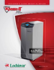
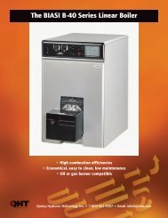
Direct Vent GasUse & Care ManualWith Installation Instructions for the Installer<strong>Tankless</strong> <strong>Water</strong> <strong>Heater</strong>! Warning: This water heater is not suitablefor use in manufactured (mobile) homes!PalomaPH-25RDVS (N,P)Rheem/ EcosenseRTG-66DV (N,P)ECO-180DV (N,P)Ruud RUTG-66DV (N,P)RichmondRMTG-66DV (N,P)The purpose of this manual is twofold: one, to provide the installer withthe basic directions and recommendations for the proper installationand adjustment of the water heater; and two, to the owner–operator,to explain the features, operation, safety precautions, maintenance andtroubleshooting of the water heater. This manual also includes a partslist.It is very important that all persons who are expected to install, operateor adjust this water heater read the instructions carefully so they mayunderstand how to perform these operations. If you don’t understandthese instructions or any terms within it, seek professional advice.Any questions regarding the operation, maintenance, service or warrantyof this water heater should be directed to the seller from whom it waspurchased. If additional information is required, refer to the section onIf You Need Service.Do not destroy this manual. Please read carefully and keep in a safeplace for future reference.Recognize this symbol as an indication of Important SafetyInformation!!!Direct Vent <strong>Water</strong> <strong>Heater</strong>! California Proposition 65 Warning: This product containschemicals known to the State of California to cause cancer, birthdefects or other reproductive harm.WARNING: If the information in these instructions is not followed exactly,a fire or explosion may result, causing property damage, personal injury or death.! FOR YOUR SAFETY!— Do not store or use gasoline or otherflammable vapors or liquids or othercombustible materials in the vicinity ofthis or any other appliance. To do so mayresult in an explosion or fire.— WHAT TO DO IF YOU SMELL GAS● Do not try to light any appliance.● Do not touch any electrical switch; do notuse any phone in your building.● Immediately call your gas supplierfrom a neighbor’s phone. Follow thegas supplier’s instructions.● If you cannot reach your gas supplier, callthe fire department.● Do not return to your home until authorizedby the gas supplier or fire department.— Improper installation, adjustment,alteration, service or maintenance can causeproperty damage, personal injury or death.Refer to this manual. Installation and servicemust be performed by a qualified installer,service agency or the gas supplier.DESIGN31-92683-000 Printed in JapanCERTIFIEDRCERTIFIED®AP14558-1 (09/08)AP14558-1 (09_08) DV 66 Manual.indd 19/17/2008 3:07:52 PM
Safety InformationSafety Precautions....... 3–6LP Gas Models ............ 5Installation InstructionsLocation.................. 7Inspect Shipment........... 8Venting................ 9-14<strong>Water</strong> Connections .... 15, 16FOR YOUR RECORDSWrite the model and serial numbers here:##You can find them on a label on the appliance.Staple sales slip or cancelled check here.Proof of the original purchase date is needed to obtain serviceunder the warranty.Relief Valve.............. 17Gas Supply............. 18High Altitude............. 18Remote Control........ 19, 20Electrical Connection...... 21Typical Installation ........ 22Pipe Insulation............ 23Installation Checklist...... 24Operating InstructionsREAD THIS MANUALInside you will find many helpful hints on how to use andmaintain your water heater properly. A little preventive careon your part can save you time and money over the life of yourwater heater.You’ll find many answers to common problems inthe Troubleshooting Guide. If you review the chart ofTroubleshooting Tips first, you may not need to call for service.Lighting Instructions...... 25<strong>Water</strong> Temperature ..... 26, 27Care and CleaningMaintenance............ 28Housekeeping ........ 28, 29Vent Inspection ........... 29Burner Inspection ........ 29Extended Shut-Down...... 29Draining................ 30Freeze Protection.......... 30Troubleshooting TipsBefore You CallFor Service........... 31, 32Customer ServiceParts List............... 33If You Need Service ....... 36Qualified Installers Only!Maximum TemperatureAdjustment............. 34Minumum TemperatureAdjustment............. 35READ THE SAFETY INFORMATIONYour safety and the safety of others are very important. Thereare many important safety messages in this manual and on yourappliance. Always read and obey all safety messages.!Thisis the safety alert symbol. Recognize this symbolas an indication of Important Safety Information!This symbol alerts you to potential hazards that cankill or hurt you and others.All safety messages will follow the safety alert symbol andeither the word “DANGER”, “WARNING”, “CAUTION”or “NOTICE”.These words mean:! DANGER An imminently hazardous situationthat will result in death or seriousinjury.! WARNING A potentially hazardous situation thatcould result in death or serious injuryand/or damage to property.! CAUTION A potentially hazardous situation thatmay result in minor or moderateinjury.Notice:Attention is called to observe aspecified procedure or maintaina specific condition.High Altitude Adjustment... 352AP14558-1 (09_08) DV 66 Manual.indd 29/17/2008 3:07:52 PM
IMPORTANT SAFETY INFORMATION.READ ALL INSTRUCTIONS BEFORE USING.Be sure to read and understand the entire Use and Care Manual before attempting to install or operate thiswater heater. It may save you time and money. Pay particular attention to the Safety Instructions. Failure tofollow these warnings could result in serious bodily injury or death. Should you have problems understandingthe instructions in this manual, or have any questions, STOP, and get help from a qualified service technician,or the local gas utility.DANGER!Install and properly vent the water heater…Failure to install and properly vent the water heater to the outdoors as outlined in theVenting Section of the Installation Instructions in this manual can result in unsafe operationof the water heater. To avoid the risk of fire, explosion or asphyxiation from carbonmonoxide, never operate this water heater unless it is properly vented and has an adequateair supply for proper operation.Be sure to inspect the vent terminal, the air intake, and the coaxial vent system on the waterheater for proper installation at initial start-up; and at least annually thereafter. Refer tothe Care and Cleaning section of this manual for more information regarding coaxial ventsystem inspection.WARNING!Gasoline, as well as other flammable materials and liquids (which include, but are notlimited to adhesives, solvents, paint thinners etc.), and the vapors they produce areextremely dangerous. DO NOT handle, use or store gasoline or other flammable orcombustible materials anywhere near or in the vicinity of a water heater or any otherappliance. Be sure to read and follow the labels on the water heater, as well as the warningsprinted in this manual. Failure to do so can result in property damage, bodily injury ordeath.DANGERFLAMMABLESFlammable VaporsVapors from flammableliquids will explode andcatch fire causing death orsevere burns.Do not use or store flammableproducts such as gasoline,solvents or adhesives in thesame room or area near thewater heater.Keep flammable products:1. far away from heater,2. in approved containers,3. tightly closed and4. out of children's reach.<strong>Water</strong> heater has a mainburner flame.The main burner flame:1. which can come onat any time and2. will ignite flammablevapors.Vapors:1. cannot be seen,2. are heavier than air,3. go a long way on thefloor and4. can be carried fromother rooms to themain burner flame byair currents.Installation:Do not install water heaterwhere flammable products willbe stored or used unless themain burner flame is at least18" above the floor. This willreduce, but not eliminate, therisk of vapors being ignitedby the main burner flame.Read and follow water heater warnings and instructions. Ifowners manual is missing, contact the retailer or manufacturer.3AP14558-1 (09_08) DV 66 Manual.indd 39/17/2008 3:07:52 PM
IMPORTANT SAFETY INFORMATIONREAD ALL INSTRUCTIONS BEFORE USING.Notice:Displayshows°F only.! DANGER!water temperature SettingSafety and energy conservation are factors to be considered when selecting the watertemperature setting of a water heater’s remote control. <strong>Water</strong> temperatures above125°F (52°C) can cause severe burns or death from scalding. Be sure to read and followthe warnings outlined on the label pictured below. °Higher (Hotter)PRIORITY°FPOWERON/OFFLower (Cooler)85 100 102 104 106 108 110 112 114 116 118 120* 125 130 135 140 150 160 170 185 °F2938 39 40 41 42 43 44 46 47 48 49*52 54 57 60 66 71 77 85 °C* Temperatures 85°F(29°C) and above 120°F (49°C)can be achieved with the Main (UMC-117) remotecontrol. See page 34 & 35 for minimum andmaximum temperature adjustment.4Time/Temperature Relationship in Scalds<strong>Water</strong> TemperatureTime To Produce a Serious Burn120°F (49°C) More than 5 minutes125°F (52°C) 1 1 /2 to 2 minutes130°F (54°C) About 30 seconds135°F (57°C) About 10 seconds140°F (60°C) Less than 5 seconds145°F (63°C) Less than 3 seconds150°F (66°C) About 1 1 /2 seconds155°F (68°C) About 1 secondTable courtesy of Shriners Burn InstituteThe chart shown above may be used as a guide indetermining the proper water temperature for your home.! DANGER: Households with small children, disabledor elderly persons may require a 120°F (49°C) or lowertemperature setting to prevent contact with “HOT” water.Maximum water temperature occurs while burner is on.To find water temperature being delivered, turn on a hotwater faucet and place a thermometer in the water streamand read the thermometer. (See page 26 & 27 for moredetails.)The temperature of the water at the outlet of the waterheater can be regulated by setting the temperature onRemote Control. The remote control was set at 100°F(38°C) before it was shipped from the factory.The diagram to the bottom left illustrates the RemoteControl and how to adjust the water temperature.Notice: The factory setting allows operating temperaturesbetween 100°F (38°C) and 120°F (49°C). Temperaturesof 85°F (29°C) and above 120°F (49°C) can be achievedwith the MAIN (UMC-117) remote control. Temperaturesof 85°F (29°C) can be achieved with the Bath (USC-117or USC2-117) remote control. Only qualified servicepersonnel should perform this adjustment. Only factoryauthorized remote control(s) should be used.Notice: When this water heater is supplying generalpurpose hot water requirements for use by individuals,a thermostatically controlled mixing valve for reducingpoint of use water temperature is recommended to reducethe risk of scald injury. Contact a licensed plumber or thelocal plumbing authority for further information.Notice: Only commercial products can achievetemperatures up to 185° (85° C).AP14558-1 (09_08) DV 66 Manual.indd 49/17/2008 3:07:52 PM
DANGER!Natural gas and liquefied petroleum modelsBoth LP and natural gas have an odorant added to aid in detecting a gas leak. Somepeople may not physically be able to smell or recognize this odorant. If you are unsure orunfamiliar with the smell of LP or natural gas, ask the gas supplier. Other conditions, such as“odorant fade”, which causes the odorant to diminish in intensity, can also hide or camouflagea gas leak.● <strong>Water</strong> heaters utilizing LP gas are differentfrom natural gas models. A natural gaswater heater will not function safely on LPgas and vice versa.● No attempt should ever be made toconvert the water heater from natural gasto LP gas. To avoid possible equipmentdamage, personal injury or fire, do notconnect the water heater to a fuel type notin accordance with the unit data plate;propane for propane units and natural gasfor natural gas units. These units are notcertified for any other fuel type.● LP appliances should not be installed belowgrade (for example, in a basement) if suchinstallation is prohibited by federal, stateand/or local laws, rules, regulations orcustoms.● Propane or LP gas must be used with greatcaution. It is heavier than air and willcollect first in lower areas, making it hardto detect at nose level.● Before attempting to light the water heater,make sure to look and smell for gas leaks.Use a soapy solution to check all gas fittingsand connections. Bubbling at a connectionindicates a leak that must be corrected.When smelling to detect a gas leak, be sureto sniff near the floor also.● Gas detectors are recommended in LPand natural gas applications and theirinstallation should be in accordancewith the detector manufacturer’srecommendations and/or local laws,rules, regulations or customs.● It is recommended that more than onemethod, such as soapy solution, gasdetectors, etc., be used to detect leaksin gas applications.Notice: If a gas leak is present or suspected:● Do not attempt to find the cause yourself.● Do not try to light any appliance.● Do not touch any electrical switch.● Do not use any phone in your building.● Leave the building immediately and makesure your family and pets leave also.● Leave the doors open for ventilation andcontact the gas supplier, a qualified serviceagency or the fire department.● Stay away from the building until theservice call has been made, the leak iscorrected and a qualified agency hasdetermined the area to be safe.5AP14558-1 (09_08) DV 66 Manual.indd 59/17/2008 3:07:52 PM
IMPORTANT SAFETY INFORMATIONREAD ALL INSTRUCTIONS BEFORE USING.!WARNING!For your safety, the information in this manual must be followed to minimize the riskof fire or explosion, electric shock, or to prevent property damage, personal injury orloss of life.FOR INSTALLATIONS IN THE STATE OF CALIFORNIACalifornia Law requires that water heaters must be braced, anchored or strapped to resistfalling or horizontal displacement due to earthquake motions. For water heaters up to 52gallon capacity, a brochure with generic earthquake bracing instructions can be obtained from:Office of the State Architect, 1102 Q Street, Suite 5100, Sacramento, CA 95814 or you may call916-445-8100 or ask a water heater dealer.However, applicable local codes shall govern installation. For residential water heatersof a capacity greater than 52 gallons or tankless-style, consult the local building jurisdictioncode for acceptable bracing procedures.SAFETY PRECAUTIONSHave the installer show you the location of the gas shut-off valve and how to shut it offif necessary. Turn off the manual shut-off valve if the water heater has been subjectedto overheating, fire, flood, physical damage or if the gas supply fails to shut off.● Read this manual entirely before installingor operating the water heater.● Use this appliance only for its intendedpurpose as described in this Use and CareManual.● Be sure your appliance is properly installedin accordance with local codes and theprovided installation instructions.● Do not attempt to repair or replace anypart of your water heater unless it isspecifically recommended in this manual.All other servicing should be referred to aqualified technician.Read and follow this Safety Information carefully.SAVE THESE INSTRUCTIONS6AP14558-1 (09_08) DV 66 Manual.indd 69/17/2008 3:07:52 PM
Installing the water heater :This water heater must be installed in accordance with these instructions, local codes, utility companyrequirements and/or in the absence of local codes, use the latest edition of the American National Standard/National Fuel Gas Code. A copy can be purchased from either the American Gas Association, 400 NorthCapitol Street Northwest, Washington, DC 20001 as ANSI standard Z223.1 or National Fire ProtectionAssociation, 1 Batterymarch Park, Quincy, MA 02269 as NFPA 54. In Canada, the latest edition of the CSAB149.1 Natural Gas and Propane Installation, and the Canadian Electrical Code, CSA C22.1 Part 1, in theabsence of local codes.Location of <strong>Water</strong> <strong>Heater</strong>! WARNING:Combustible constructionrefers to adjacent wallsand ceilings and should notbe confused withcombustible or flammableproducts and materials.Combustible and/orflammable products andmaterials should never bestored in the vicinity of thisor any gas appliance.Minimum Clearance fromCombustible andNon-CombustibleConstruction.min.1/2 "(1.3 cm)min. 1" min. 1"(2.5 cm) (2.5 cm)min.1/2 "(1.3 cm)min. 12" (30 cm)(24" (61 cm) minimum isrecommended for service)To p 12" (30 cm) Back = 0" *Top = 12" (30 cm) Bottom = 12"CoAxial Vent = Side = 1/2" (1.3 cm)Front 1" (2.5 = 12" cm) (30 cm) Bottom Back = 12" 0"* (30 cm)Front 12" (30 cm)* Side (with = 1/2" support bracket) CoAxial Vent = 1"* (with support bracket)! WARNING: Follow ventmanufacturer’s instructionwhile installing vent. Ifrequired, provideadditional clearances fromvent to combustibles pervent manufacturer’sinstruction.The water heater should not be located inan area where leakage of the heat exchangeror connections will result in damage to thearea adjacent to it or to lower floors of thestructure.When such areas cannot be avoided, it isrecommended that a suitable catch pan,adequately drained, must be installed underthe water heater.The pan must not restrict combustionair flow.A gas fired water heater or any other applianceshould not be installed in a space where liquidswhich give off flammable vapors areto be used or stored. Such liquids includegasoline, LP gas (butane or propane), paintor adhesives and their thinners, solventsor removers.Because of natural air movement in a room orother enclosed space, flammable vapors can becarried some distance from where their liquidsare being used or stored. The open flame ofthe water heater’s main burner can ignite thesevapors causing an explosion or fire whichmay result in severe burns, death or propertydamage.The water heater must be located so it is notsubject to physical damage, for example, bymoving vehicles, area flooding, etc.If the water heater is installed in a garage, itshould be installed so that the direct ignitionsystem and main burner are no less than 18inches (45 cm) above the garage floor.Raising the gas fired water heater will reduceBUT NOT eliminate the possibility of lightingthe vapor of any flammable liquids which maybe improperly stored or accidentally spilled.● The water heater should be installed asclose as practical to the vent terminationto minimize vent length and the number ofelbows required for venting.1” (2.5 cm) min● The water heater should be installed withthe proper venting materials and terminationsuitable for Category III venting.● A fire stop plate should be installed at everypenetration of a floor or ceiling if the vent isnot running in a fire rated shaft.● Failure to install and properly vent the waterheater to the outdoors as outlinedin the Venting Section of this manualcan result in unsafe operation.● Long hot water lines should be insulated toconserve water and energy.● The water heater and water lines shouldbe protected from exposure to freezingtemperatures.● Do not install the water heater inbathrooms, bedrooms, any occupied roomsnormally kept closed, or in outdoor areas.● Do not install water heater where subjectto vibrations.● Do not install the water heater inRecreational Vehicles, Mobile Homes,Boats and other <strong>Water</strong>crafts.● Do not install the water heater near ventsfor heating or cooling. A minimum of 4 feet(1.2 m) should be maintained.● Minimum clearance from combustible andnon-combustible construction is 1/2” (1.3cm) sides, 0” rear (with support bracket);12” (30 cm) from the bottom; 12” (30 cm)from the front of the water heater; and 12”(30 cm) from the top (24” [61 cm] fromfront and top is recommended for servicingpurposes).● Maintain a minimum clearance of1” (2.5 cm) around the coaxial ventpipe to combustible or non-combustibleconstruction, unless otherwise specifiedby vent manufacturer or installed in anenclosed space. If the clearances stated onthe Instruction/Warning Label, located onthe front panel of the heater differ, installthe water heater accordingto the clearances stated on the label.1” (2.5 cm)min1” (2.5 cm)minCoaxial Vent Pipe& Air Intake7AP14558-1 (09_08) DV 66 Manual.indd 79/17/2008 3:07:53 PM
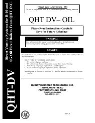
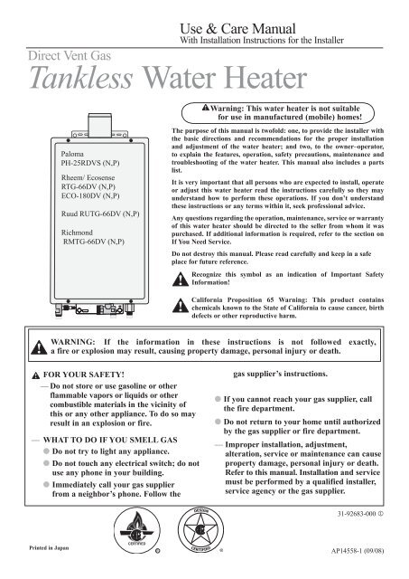
ON/OFFCOMMERCIALW A T E R H E A T E R SCOMMERCIALTANKLESSGAS WATER HEATERSWITH A 3YEAR HEAT EXCHANGER AND1YEAR PARTS LIMITED WARRANTY®AP13487-1 (03/05)Use & Care ManualWith Installation Instructions for the InstallerThe purpose of this manual is twofold: one, to provide the installer withthe basic directions and recommendations forthe proper installation andadjustment of the water heater; and two, to the owner–operator, toexplain the features, operation, safety precautions, maintenance andtroubleshooting of the water heater. This manual also includes a partslist.It is imperative that all persons who are expected to install, operate oradjust this water heater read the instructions carefully so they mayunderstand how to perform these operations. If you don’t understandthese instructions or any terms within it, seek professional advice.Any questions regarding the operation, maintenance, service orwarranty of this water heater should be directed to the sellerfrom whomit was purchased. If additional information is required, refer to thesection on How to Obtain Service Assistance.Do not destroy this manual. Please read carefully and keep in a safeplace for future reference.! Recognize this symbol as an indication of Important SafetyInformation!California Proposition 65 Warning: This product contains! chemicals known to the State of California to cause cancer, birthdefects or other reproductive harm.WARNING: If the information in these instructions is not followed exactly,! a fire or explosion may result causing property damage, personal injury or death.! FOR YOUR SAFETY!— Do not store or use gasoline or other If you cannot reach your gas supplier, callflammable vapors or liquids or other the fire department.combustible materials in the vicinity of this or Do not return to your home until authorizedany other appliance. To do so may result in an by the gas supplier or fire department.explosion or fire.— Improper installation, adjustment,— WHAT TO DO IF YOU SMELL GASalteration, service or maintenance can cause Do not try to light any appliance.property damage, personal injury, or death .Refer to this manual. Installation and service Do not touch any electrical switch; do notmust be performed by a qualified installer,use any phone in your building.service agency or the gas supplier. Immediately call your gas supplier from aneighbor’s phone. Follow the gassupplier’s instructions.Printed in USAWarning: This water heater is not suitable foruse in manufactured (mobile) homes!DESIGNCERTIFIED®<strong>Tankless</strong> UnitInstalling the water heater:NOTICE: The water heatershould not be installed nearan air supply containinghalogenated hydrocarbons.Corrosive AtmospheresThe air in beauty shops, dry cleaningestablishments, photo processing labs,and storage areas for liquid and powderedbleaches or swimming pool chemicalsoften contains such halogenatedhydrocarbons.An air supply containing halogenatedhydrocarbons may be safe to breathe,but when it passes through a gas flame,corrosive elements are released thatwill shorten the life of any gas burningappliance.Propellants from common spray cansor gas leaks from A/C and refrigerationequipment are highly corrosive afterpassing through a flame.The water heater warranty is voided whenfailure of the heater is due to operation ina corrosive atmosphere.Inspect ShipmentInspect the water heater for possible damage. Check the markings on the rating plate ofthe water heater to be certain the type of gas supplied corresponds to the water heaterrequirements. Verify all included parts are present (see below).Certificate ofLimitedWarranty<strong>Tankless</strong>Residential Gas<strong>Water</strong> <strong>Heater</strong>sPRIORITY°FWood Screw x 5pcs.Drain TubingPOWERRemote ControlAssembly KitWasher x 4 pcs.WarrantyUse & Care ManualManual ApplianceGas Shut-off Valve8AP14558-1 (09_08) DV 66 Manual.indd 89/17/2008 3:07:53 PM
The water heater must be installed with a 3”/5” diameter UL approved Category III Coaxial Stainless Steelappliance coaxial vent pipe and an appropriate adapter.DANGER: Failure toinstall the appliance ventadapter and properly ventthe water heater to theoutdoors as outlined in theVenting section of thismanual will result in unsafeoperation of the waterheater, causing death,serious injury, explosion,or fire. To avoid the riskof fire, explosion, orasphyxiation from carbonmonoxide, NEVER operatethe water heater unless it isproperly vented and hasadequate air supply forproper operation asoutlined in the Ventingsection of this manual.WARNING: Use 3”/5”UL approved Category IIIStainless Steel ventmaterial only. No othervent material is permitted.WARNING: Refer topage 7 for clearances tocombustible material.Numberof 90°elbows(bends)MaximumLength ofStraightPipe1 26’(8.0 m)2 24' 6"’(7.5 m)3 23"(7.0 m)4 21' 6"(6.5 m)2’(61 cm)Max.VentingThe installation of venting must complywith national codes, local codes and thevent manufacturer’s instructions.The water heater must be vented to theoutdoors as described in these instructions.DO NOT connect this water heater to achimney. It must be vented separately fromall other appliances.All coaxial vent components (adapters, pipe,elbows, terminals, etc.) should be UL 1738Certified Stainless Steel Venting Material(e.g. AL29-4C).The specified vent termination must be used.(Refer to pages 13 and 14 for an example ofthe concentric vent.)Use the screws provided to connect thecoaxial vent pipe with the anti-disconnectionjoint.Follow coaxial vent manufacturer’sinstallation instructions and theirrecommended clearances to combustibles.The unit can be vented either horizontallyor vertically.Coaxial vent pipe runs must be adequatelysupported along both horizontal and verticalruns.The maximum recommended unsupportedspan should be no more than five (5) feet(1.5 m). Support isolation hanging bandsshould be used. DO NOT use wire. (Seediagram below).Venting LengthsMAXIMUM VENT LENGTH: Thesystem will not operate if there is excessiverestriction (pressure drop) in the ventingsystem. A maximum 26’(8.0 m) of vent pipemay be used provided there is only one 90°elbow in the system. If additional elbows arerequired: two elbows can be used with 24’6"(7.5 m), three elbows can be used with 23’(7.0 m) or four elbows can be used with 21’6" (6.5 m) of vent pipe.A 90° elbow is equivalent to 1’6” (.5 m) ofstraight pipe. A 45° elbow is equivalent to9” (.25 m) of straight pipe.The vent termination does not count asstraight pipe when determining total ventlengths.94° ElbowFireStop7/8" per footdownward slopeVent PipeWall PlatesNotes on pre-existing vent:NO!YES!If the water heater is being installed as areplacement for an existing water heater, athorough inspection of the existing ventingand air intake system must be performedprior to any installation work. Verify that thecorrect materials, vent lengths and terminallocations as detailed in this Use and CareManual have been met. Carefully inspect theentire venting and air intake system for anysigns of cracks or fractures, particularly atthe joints between elbows or other fittingsand the straight runs of vent pipe. Check thesystem for signs of sagging or other stressesin the joints as a result of misalignment ofany components in the system. If any ofthese conditions are found, they must becorrected in accordance with the ventinginstructions in this manual before completingthe installation and putting the water heaterinto service.See the back page of this manualfor additional requirements for theCommonwealth of Massachusetts.The 94° elbow is equivalent to a 90° elbow.The vent should be installed with a slightdownward slope of 7/8” per foot ofhorizontal run toward the vent terminal (seediagram below). This ensures that anycondensate formed during operation of theunit is evacuated from the appliance and toprevent rain from entering the appliance.An upward slope toward the vent terminal isnot acceptable for horizontal venting.MINIMUM VENT LENGTH: The ventingmay be as short as 12” (30 cm), providedone vent termination is installed to theoutdoors through a sidewall, one 94° elbowis included in the installation and the wallplates are installed.Notice: Make sure that the seam of the innervent pipe in horizontal runs is toward thetop of the installation (see diagram to the farleft).Vent SeamCeilingBoardInspectionAccess Panel #1InspectionAccessPanel #29AP14558-1 (09_08) DV 66 Manual.indd 99/17/2008 3:07:54 PM
Installing the water heater:2’(61 cm)Max.94° ElbowFireStop7/8" per footdownward slopeInspectionAccess Panel #1CeilingBoardVent PipeWall PlatesInspectionAccessPanel #2Venting Through Closed SpacesIf the coaxial vent piping passes through a closed space, a minimumclearance of 1” (2.5 cm) when installed horizontally or 6” (15 cm) wheninstalled vertically should be maintained between the coaxial vent pipeand combustibles and noncombustibles. Be sure to follow local codesand vent manufacturer’s installation instructions.For maintenance and inspection purposes, the following access panelsare required.● Two (2) inspection access panels large enough to allow access forventing inspection. One (1) of these access panels should be closeto where the coaxial vent pipe enters the ceiling. The other accesspanel should be near the vent termination.● A ventilation access panel with a 16 in 2 (103 cm 2 ) opening shouldbe provided every 10 ft (3 m).CAUTION: Ensure thatthe appliance vent adapter issecurely attached to the waterheater collar.ExhaustFlowAApplianceVent AdapterCollarAppliance Vent AdapterThe water heater must be installedwith a UL 1738 approved Category IIIStainless Steel appliance coaxial ventadapter.Read the following instructions beforeinstallation.● Test fit the adapter over the water heatercollar before proceeding.● Slide adapter end “A” down over heatercollar “B” as far as it will go.● Use the screws provided with the ventadapter to attach the adaptor to the heatercollar.NOTICE: Follow the appliance coaxial ventadapter manufacturer’s instructions.B<strong>Water</strong> <strong>Heater</strong>CAUTION: Condensateis known to be acidic; referto local, state (provincial)or federal codes for properhandling and dischargemethods.CAUTION: Condensatemust drain away from thewater heater and shouldnot be allowed to drainback into any part of thevent system.WARNING: Failure toprovide a vent condensatedrain close to the appliancecould allow acidic flue gascondensate to enter intoappliance flueways, causingpremature failure of theappliance.Draining the CondensateProvision should be made to collect anddispose of condensate from venting systems.When a water heater is vented horizontally,the vent pipe can have a DOWNWARD orUPWARD slope towards the termination. Ifan UPWARD slope is used, a condensate trapmust be installed as close as practical to thewater heater in order to prevent condensatefrom draining back into the water heater.See Examples A and B on page 13 and 14for DOWNWARD and UPWARD slope forhorizontally vented water heaters.When a water heater is vented vertically,an UPWARD slope must always be used.A condensate trap must be installed in thehorizontal section of the vent and as closeas practical to the water heater in order toprevent condensate from draining back intothe water heater. See the diagram on page 14showing UPWARD slope for verticallyvented water heaters.Always attach a drain hose to the drain fittingand plumb the hose to a sanitary sewer drain.A high temperature silicone tubing suitable foruse with acidic condensate and appropriate forthe temperature range should be used.The drain tube is fashioned into a “pigtail” trapand must be filled with water to prevent fluegases from emitting into the building prior tooperating the appliance.10AP14558-1 (09_08) DV 66 Manual.indd 109/17/2008 3:07:55 PM
GvHADVLEVBFCvvFIXEDCLOSEDOPERABLEBBvCLOSEDOPERABLE FIXEDvBAJBXvIMvKXBV Vent Terminal X Air Supply Inlet Area Where Terminal is NOT PermittedHorizontal Vent Terminal LocationThe following information should be used for determining the proper location of the ventterminal for direct vent tankless water heaters.Canadian Installations 1 US Installations 2A= Clearance above grade, veranda,porch, deck or balcony. 12 inches (30 cm) above anticipatedsnow level.B= Clearance to window or door thatmay be opened. 6 inches (15 cm) for appliances < 10,000Btuh (3 kW), 12 inches (30 cm) forappliances > 10,000 Btuh (3kW) and 100,000 Btuh (30kW).12 inches (30 cm) above anticipatedsnow level.6 inches (15 cm) for appliances 10,000 Btuh (3kW)and < 50,000 Btuh (15kW), 12 inches(30 cm) for appliances > 50,000 Btuh(15kW).C= Clearance to permanently closedwindow. * *D= Vertical Clearance to ventilatedsoffit located above the terminalwithin a horizontal distance of 2feet (61 cm) from the center line ofthe terminal.* *E= Clearance to unventilated soffit.F= Clearance to outside corner.* ** *G= Clearance to corner. * *H = Clearance to each side of center lineextended meter/regulator assembly.above 3 feet (91 cm) within a height 15 feet(4.57 m) above the meter/regulatorassembly.I = Clearance to service regulatorcoaxial vent outlet. 3 feet (91 cm) *J = Clearance to nonmechanical airsupply inlet to the combustionair inlet to any building or otherappliance. 6 inches (15 cm) for appliances 10,000 Btuh (3kW)and < 100,000 Btuh (30kW), 36 inches(91 cm) for appliances > 100,000 Btuh(30kW).*6 inches (15 cm) for appliances < 10,000Btuh (3 kW), 9 inches (23 cm) forappliances > 10,000 Btuh (3kW) and 50,000 Btuh (15kW).K = Clearance to mechanical air supplyinlet.L = Clearance above paved sidewalk orpaved driveway located on publicproperty.6 feet (1.83 m)3 feet (91 cm) above if within 10 feet(3 m) horizontally.7 feet (2.13 m)† *M = Clearance under veranda, porch,deck or balcony. Not Allowed Not Allowed1 In accordance with current CSA-B149.1 Installation Codes.2 In accordance with current ANSI Z223.1/ NFPA 54 National Fuel Gas Code.† A vent shall not terminate directly above a sidewalk or paved driveway that is located between two single familydwellings and serves both dwellings.* For clearances not specified in ANSI 223.1/NFPA 54 or CSA-B149.12, one of the following shall be indicated:a) A minmum clearance value determined by testing in accordance with section 2.20, or;b) A reference to the following footnote: "Clearance in accordance with local installtion codes and the requirementsof the gas supplier."11AP14558-1 (09_08) DV 66 Manual.indd 119/17/2008 3:07:55 PM
Installing the water heater:Indoor <strong>Water</strong> <strong>Heater</strong>InsideCornerIf soffit vent is too close,block off and install newvent at another location.Caulk6’ (1.8 m)Caulk ZoneCaulkWARNING: Moisture in the flue gas will condense as itleaves the vent terminal. In cold weather this condensate canfreeze on the exterior wall, under the eaves and onsurrounding objects. Some discoloration to the exterior ofthe building is to be expected. However, improper locationor installation can result in severe damage to the structureor exterior finish of the building6’(1.8 m)Rising moisture willcollect under eaves.6’ (1.8 m)Caulkzone or to edge of windowetc.,starting within 6’ (1.8 m).CaulkRTV silicone caulk4’ 1 ft. sq. (30 x 30 cm) sheet metal plate onbrick or masonry surface, recommended.(1.2 m)WARNING: For multiple unit installation, a minimumdistance between vent terminations must be maintained toprevent recirculation of vent gases. Maintain a center-to-centerdistance between vent terminations of 19 inches (48 cm) for twounit installation. Maintain a center-to-center distance betweenvent terminations of 21 inches (53 cm) for three or more unitinstallation.Additional ConsiderationsDo NOT install vent terminal under any patio or deck.To help prevent moisture from freezing on walls and undereaves, do not locate vent terminal on the side of a build ing withprevailing winter winds.To help prevent water lines from freezing, do not locate ventterminal on the side of a building with prevailing winter winds.Do NOT terminate vent directly on brick or masonary surfaces. Arust resistant sheet metal backing plate (1x1 foot) (30x30 cm) isrecommended behind vent. See figure on left. Do Not locate vent terminal too close to shrubbery, as flue gasesmay damage them.Caulk all cracks, seams and joints within six (6) feet (1.8 m) ofvent terminal.Caulk around wall face plate for weather tight seal.All painted surfaces should be primed to lessen the chance ofphysical damage. Painted surfaces will require maintenance.Insulate vent pipe of water heaters exposed to cold conditions(attics, crawl spaces, etc.) with inflammable material to help preventmoisture from accumulating in the vent pipe. The insulation shouldbe rated for the temperature and should not contain substances thatcorrode the vent pipe.Do NOT extend exposed vent pipe of indoor water heaters outsideof building.Guard vent against accidental contact with people and pets.12AP14558-1 (09_08) DV 66 Manual.indd 129/17/2008 3:07:56 PM
Installing the water heater:94° ElbowApplianceVent Adapter<strong>Water</strong><strong>Heater</strong>MountingBracketsInner Wa ll PlateVentPipeSide ViewInner Wa llOuterWallOutside Wa llSide ViewOuter Wall PlateCaulk forweather sealWARNING: UseUL approved Category IIIvent material only. No othervent material is permitted.CAUTION: Follow thevent manufacturer’sinstallation instructions asdesign might vary frommanufacturer tomanufacturer.Horizontal Vent Installation continued.Use 4 hollow wall anchors, at least1/8 inch (0.32 cm) in diameter and ofappropriate length for the thickness ofthe sheathing, if sheathing is particleboard or other composite material.Use 4 #10x1-1/4” wood screws forplywood, solid wood sheathing ormembers. Use suitable masonry anchorswhen passing through solid masonrywalls. Reinstall the decorative sheathingaround the faceplate. This assembly maybe painted to match the exterior decor.Apply silicone sealant or silicone/latexcaulk around the vent section whereit passes through the plate and aroundthe plate where it is attached to thestructure. This will provide a weatherseal to keep moisture outside thebuilding. Ensure a sufficient seal ismade. Now attach the female end ofthe air intake tee to the male end of the3”/5” concentric vent pipe.Push firmly on the air intake tee untilthe outer jacket has made contact withthe snap ring located on the male end ofthe 3”/5” concentric vent pipe section.When fully assembled the outer femaleend will overlap the male end 1 inch(25.4 mm).Use the self-tapping screws providedwith the vent kit to connect the twoouter pipes.Seal the over lapping area of the outerpipe (5” concentric pipe) with a thickbead of caulk.Install the appliance adapter onto theappliance and use (4) four screws tosecure the appliance adapter to theappliance. Now attach other requiredvent and air intake material betweenthe appliance adapter and the horizontalvent termination.Maintain the proper clearance betweenthe vent pipe and combustible or noncombustiblematerial as required by thevent manufacturer.There is a 1" (2.5 cm) minimumclearance required between airintake pipe and combustible or noncombustible material.Proper support be provided for the ventand air intake pipes as mentioned in theventing section.Support method used should isolatethe vent pipe from floor joist or otherstructural members to help prevent thetransmission of noise and vibration.Do not support, pin, or otherwisesecure the venting system in a way thatrestricts the normal thermal expansionand contraction of the chosen ventingmaterial.7/8" per footdownward slopeWall Plates2’(61 cm)Max.94° ElbowFireStopVent PipeCeilingBoardInspectionAccess Panel #1InspectionAccessPanel #2Example A: Typical Horizontal Terminationw/ 7/8” per foot DOWNWARD Slope13AP14558-1 (09_08) DV 66 Manual.indd 139/17/2008 3:07:57 PM
Installing the water heater:Min. 12" (30 cm) Above Roof 1Vertical Vent Termination LocationOnly Rheem approvedtermination and partsshould be used duringinstallation.Vent PipeThrough RoofMin. 12" (30 cm) Above Anticipated Snow Level.Max. 24" (60 cm) Above Roof (Without Additional Support)The location of the vent terminal depends on the followingminimum clearances and considerations (see diagram at left):Minimum twelve (12) inches (30 cm) above roof. 2Minimum twelve (12) inches (30 cm) above anticipatedsnow level.Maximum twenty-four (24) inches (60 cm) above roof levelwithout additional support for vent.Four (4) feet (1.2 m) from any gable, dormer or otherroof structure with building interior access (i.e., vent,window, etc.).Ten (10) feet (3 m) from any forced air inlet to the building.Any fresh or make-up air inlet such as a dryer or furnacearea is considered to be a forced air inlet. 32 For installations in Canada 18" (45.7 cm).1Min. 18" (46 cm) Above Roof for installations in Canada.3 For installations in Canada 6' (1.8 m) .Notice: Only Rheemapproved terminationand parts should be usedduring installation.Notice: Follow ventmanufacturer’s installationinstructions and theirrecommended clearances tocombustibles as required.Vertical Vent InstallationA fire stop plate should be installed at everypenetration of a floor or ceiling if the ventis not running in a fire-rated shaft. Maintainthe recommended air space clearance tocombustible materials and building insulation.Once the vent terminal location has beendetermined, make a hole through the roof andinterior ceiling to accommodate the vent pipe.Complete the vent pipe installation to thewater heater’s vent connector fitting on thewater heater vent collar outlet. SupportRoof JackStormCollar3“/ 5” Concentric PipeSupportClampChase Requires6" (15 cm) Clearanceto CombustiblesFirestopVerticalTerminationAdapterAir IntakeAdjustableRoofFlashingvertical or horizontal runs as previouslymentioned. If required, use silicone sealantat the point the vent connector joins thewater heater.Install adequate flashing where the ventpipe passes through the roof. Determine thevent terminal height and install the vent pipeaccordingly. Refer to the diagram above forproper vent terminal height.The vent roof system must terminate at least1 foot (30 cm) above the roof line and at least2 feet (61 cm) higher than any portion of thebuilding within 10 feet (3 m).Install supports every 5 feet (1.5 m) verticallyalong the vent pipe route. Vertical supportsare required after every transition to verticaland are required after every offset elbow.When the vent is free-standing and penetratesa roof/ceiling, another means of support mustbe used at a second location.Follow the vent manufacturer’s recommendedinstallation instructions provided with thevent purchased from the manufacturer.1/4" per foot upward slope1" (2.5 cm) ClearanceFirestop2'(61 cm)MaxSupportHangerCondensateTrapTo Drain. Dispose ofcondensate in accordanceVent to local codesAdapterDetail ofcondensate trap.14Standard Vertical Vent TerminationAP14558-1 (09_08) DV 66 Manual.indd 149/17/2008 3:07:58 PM
CAUTION:Reinforcement of the wall isrequired in case the wall isnot strong enough to holdthe appliance.Upper BracketWasherWoodScrewWasherWoodScrew1/8" (.32 cm)ClearanceWoodScrewLower BracketThe image above may differin appearance from yourwater heater.IMPORTANT: Do notapply heat to the HOT orCOLD water connections. Ifsweat connections are used,sweat tubing to adapterbefore fitting adapter tothe water connections onheater. Any heat appliedto the water supply fittingswill permanently damagethe internal componentsof the water heater.Notice: Due to coldenviroments, ice maypotentially accumulate atthe water connections. Inthis case, please insert thepower cord of the waterheater into an electricaloutlet. The ice should meltwithing approximately 10minutes and at this time thewater connections can bemade.Mounting the <strong>Water</strong> <strong>Heater</strong>Make sure the location of the appliance allowsfor easy access and operation.Wall studs should be utilized when mountingthe water heater to the wall. Alternately, asuitable piece of wood may be placed insideor outside of the wall to span the distancebetween the wall studs. Fasten the waterheater mounting brackets to the wood.In case of dry wall or concrete wall, usedrywall anchors or lag bolts.The water heater requires 120VAC/60Hz.Have a receptacle with ground terminal nearthe water heater. The length of the powersupply cord is 6 feet (1.8 m).Install a wood screw for the upper bracketwith a clearance of 1/8” (.32 cm) between thewall and the screw head. Hang the center ofthe upper bracket on the screw.Using a wood screw and a washer, affix theThermal ExpansionA thermal expansion tank will be required ifthe water heater is installed in a closed loopsystem to prevent damage to heater, relatedpiping and relief valve. Replacing the reliefvalve will not correct the problem! Theexpansion tank is designed with an air cushionbuilt in that compresses as the system pressureincreases, thereby relieving the over pressure<strong>Water</strong> Supply ConnectionsPlumbing should be carried out by a qualifiedplumber in accordance with local codes.Use approved plumbing materials only.The diameter of the pipe lines should be aminimum of 3/4”.To conserve energy and to prevent freezing,insulate both cold and hot water supplylines. DO NOT cover the drain or pressurerelief valve.To ensure proper operation of the waterheater, the following water pressure guidelinesshould be followed:● Operation of the water heater requires theminimum water pressure of 14 psi (97 kPa)and a minimum water flow rate of 0.66gpm (2.5 lpm).● A water pressure of 40 psi (276 kPa) isrequired to achieve maximum flow rate.● To maintain proper performance, ensuresufficient water supply pressure. Thelower bracket to the wall (Left and Right).Repeat to affix the top bracket.The brackets can be adjusted to change thedistance between the back of the applianceand the wall within the range of 3/8” (.95 cm)to 1-1/2” (3.8 cm).Loosen the adjustment screws of both the topand the bottom brackets to adjust the distance(See diagram below).TOPBracketAdjustment ScrewsAdjustment ScrewsBracket BOTTOMThe image above may differ in appearancefrom your water heater.condition and eliminating the repeatedoperation of the relief valve. Other methodsof controlling thermal expansion are alsoavailable. Contact your installing contractor,water supplier or plumbing inspector foradditional information regarding this subject.Required <strong>Water</strong> Pressure = Min. Operating<strong>Water</strong> Pressure (14 psi [97 kPa]) + PipePressure Loss + Faucet and ShowerPressure Loss + Safety Margin (more than5 psi [34 kPa]).● To supply hot water to upper floors,additional water pressure (0.44 psi/ft[10 kPa/m]) must be ensured. Themeasurement should be calculated by thedistance between the water inlet of thewater heater (ground level) to the hotwater faucet (upper floor level).● Well water systems should be set to ensurea minimum system pressure of 40 psi (276kPa). The pressure should remain stableduring the operation of the water heater.● When the water is supplied from a watersupply tank, the height of the tank and thediameter of the pipes and their relationto water pressure should be taken intoconsideration. Gravity water pressure isnot recommended.15AP14558-1 (09_08) DV 66 Manual.indd 159/17/2008 3:07:59 PM
Installing the water heater:CAUTION: This waterheater must only be used withthe following water supplysystem conditions:● With clean, potable waterfree of corrosive chemicals,sand, dirt or othercontaminates.● With inlet watertemperatures above 32°F(0°C), but not exceeding120°F (49°C).● Free of lime and scaledeposits.● DO NOT reverse the hotand cold water connections.The water heater willnot operate.Clean the<strong>Water</strong> Filter<strong>Water</strong> Filter<strong>Water</strong> InletCheck ValveNipple<strong>Water</strong>Notice: Use only teflon tape oncold and hot water connections andlines.AirReliefValveHot<strong>Water</strong>Tap<strong>Water</strong> Supply Connections, continuedNotice: If the water flow resistance of ashower head is too high, the burner in thewater heater will fail to ignite. Keep theshower head clean from debris that couldcause additional pressure drop.Notice: If using mixing valves on theoutlet, choose one that prevents coldwater pressure from overcoming hot waterline pressure.Notice: If multiple water heaters areinstalled in a manifold system, thewater piping must be in “Parallel”. Awater pressure of 40 psi (276 kPa) isrecommended for each water heater forproper operation of the water heaters.Alternate <strong>Water</strong> Piping Arrangementwith Optional Valve KitValve kits may be purchased and installed asoptional items. Contact your distributor orplace of purchase for details.They allow forone person full diagnostic testing and easeof flushing the system. The kit includes twofull port isolation valves, one for the coldside and one for the hot side. Refer topage 22.Install a shutoff valve near the inlet ofthe water heater for service and drainingpurposes.It is not recommended to use pipes withsmaller diameters than the water supplyconnection of the water heater.Before connecting the water supply pipeto the water heater, open the shutoff valveand clean out sand, debris, air, caulkingmaterial, etc. inside the pipe. Connect tothe water inlet, then check water flow.Close the shutoff valve and clean thewater filter.Be sure to connect the water inlet and thehot water outlet as shown on the waterheater. If reversed, the water heater willnot function.Installation of unions or flexible copperconnections are recommended on theHOT and COLD water lines, so that thewater heater may disconnect easily forservicing, if necessary.Install a Check Valve between the waterheater and the water shutoff valve (see thetop left diagram).The following should be addressed inregards to the HOT WATER OUTLET:● Connections between the water heaterand point(s) of use should be as shortand direct as possible.● Local codes shall govern the exact typeof pipe material to be used for waterconnections.● To conserve energy and minimize heatloss, insulation of hot water piping isrecommended (see Hot and Cold PipeInsulation Installation on page 23).Notice: The flow rate of hot watermay vary when more than two faucets(appliances, fixtures, etc.) are being usedsimultaneously.Notice: The pipes MUST be completelydrainable. If the hot water faucets arelocated at a point higher than the waterheater, place a drain valve at the lowestpoint (see diagram at the left).Drain ValveThis appliance is notintended for space heatingapplication. Do notconnect this heater towaterlines previouslyused for space heatingor non-potable waterdistribution. All waterpiping and componentsshall be suitable forpotable water.16AP14558-1 (09_08) DV 66 Manual.indd 169/17/2008 3:07:59 PM
Drain Valveshown onright withouttubing.PressureReliefValveReliefValveDischargeLineDrainValveUnion<strong>Water</strong>ShutoffValveHot <strong>Water</strong>SupplyOutletDrainTube tosuitabledrainCold<strong>Water</strong>SupplyInletNotice: The above illustratesa pressure-only relief valve. Iflocal codes require a combinationtemperature and pressure reliefvalve be installed, an extensionpiece may be needed to ensure thatthe valve probe is not directly inthe flow path of the water.Relief ValveA new pressure relief valve, complyingwith the Standard for Relief Valves andAutomatic Gas Shut-Off Devices for Hot<strong>Water</strong> Supply Systems, ANSI Z21.22/CSA 4.4, must be installed at the hot wateroutlet connection of the water heater atthe time of installation. Local codes shallgovern the installation of relief valves.For safe operation of the water heater, besure that:● The pressure rating of the relief valvemust not exceed 150 psi (1034 kPa), themaximum working pressure of the waterheater as marked on the rating plate.● The BTUH rating of the relief valve mustequal or exceed the BTUH input of thewater heater as marked on its rating plate.● No valve of any type should be installedbetween the relief valve and the waterheater● Discharge from the relief valve shouldbe piped to a suitable drain to eliminatepotential water damage. Piping used shouldbe of a type approved for the distribution ofhot water.● Hot and cold water lines should beinsulated up to the water heater. Referto page 23 for details.● The discharge line must beNO SMALLER than the outlet of therelief valve and must pitch downward toallow complete drainage (by gravity) ofthe relief valve and discharge line.● The end of the discharge line should notbe threaded or concealed and should beprotected from freezing. No valve of anytype, restriction or reducer coupling shouldbe installed in the discharge line.Notice: Local codes govern the installationof relief valves. If local codes require that atemperature and pressure relief valve shouldbe installed, the manufacturer recommendsa type 40XL Watts T&P relief valve or anequivalent model be used.Notice: Manual operation of relief valvesshould be performed at least once a year. Turnoff the electrical power and gas shutoff valve.Lift and release lever on the relief valve andcheck the manual operation of the relief valve.You should take precaution to avoid contactwith the hot water coming out of the reliefvalve and to prevent water damage.Notice: If the relief valve on the systemdischarges periodically, a problem exists andservice to the water system is required.The vinyl tubing as shown is supplied andconnects to the drain valve located at the hotwater outlet as shown in the diagram at left.Route the other end of the vinyl tubing to thedrain pan or a suitable drain where leakagefrom the heater will not result in damage tothe area adjacent to the heater or to lowerfloors of the structure.17AP14558-1 (09_08) DV 66 Manual.indd 179/17/2008 3:08:00 PM
Installing the Main Remote Control:WARNING: Do not attempt to convert this water heater for use with a different type of gas other than the type shownon the rating plate. Such conversion could result in hazardous operating conditions.Gas SupplyManualGasSupplyLineShutoff(Valve)Manual GasApplianceShutoff(Supplied)UnionSediment TrapCapThe supplied Manual Gas Appliance ShutoffValve must be installed at the gas connection ofthe water heater at the time of installation (seediagram to the left).The branch gas supply line to the water heatershould be a minimum of 3/4” black steel pipeor other approved gas piping material.A ground joint union or ANSI design certifiedsemi-rigid or flexible gas appliance connectorshould be installed in the gas line close to thewater heater. The National Fuel Gas Code(NFGC) ANSI Z223.1 and CAN B149 codemandates a manual gas shut-off valve: SeeNFGC & B149 for complete instructions.If flexible connectors are used, the maximumlength shall not exceed 36” (91 cm).If lever type gas shut offs are used, they shallbe T-Handle type.Compound used on the threaded joints of thegas piping must be of the type resistant to theaction of LP gas. Use compound sparingly onmale threads only.A sediment trap should be installed at thebottom of the gas line.Do not use excessive force (over 31.5 ft lbs.[42.7 Nm]) in tightening the pipe, particularly ifteflon pipe compound is used, as the unit maybe damaged.The inlet gas pressure to the water heater mustnot exceed 10.5” w.c. (2.6 kPa) for natural or14” w.c. (3.5 kPa) for LP gas. For purposesof input adjustment, the minimum inlet gaspressure (with main burner on) is shown onthe water heater rating plate. If high or low gaspressures are present, contact your gas supplierfor correction.NOTICE: To ensure proper operation of theheater the gas pipe and gas meter must be sizedcorrectly.Gas piping shall be in accordance with local,utility company requirement and/or in theabsence of local codes, use the latest edition ofthe National Fuel Gas Code. In Canada, the latestedition of CSA B149.1 Natural Gas and Propaneinstallation code.WARNING: Never usean open flame to test forgas leaks, as propertydamage, personal injury,or death could result.Leak TestingThe water heater and its gas connections mustbe leak tested at normal operating pressuresbefore it is placed in operation.Turn on the gas shut-off valve(s) to thewater heater.Use a soapy water solution to test forleaks at all connections and fittings.Bubbles indicate a gas leak that mustbe corrected.The factory connections should also be leaktested after the water heater is placed inoperation.WARNING: Install a gaspressure regulator, in thegas supply line, which doesnot exceed the maximumsupply pressure.DO NOT use an industrialtype gas regulator.18Pressure Testing the Gas Supply SystemThe water heater and its manual gas shutoffvalve must be disconnected from the gassupply piping system during any pressuretesting of the system at pressures in excessof 1/2 psi (14” w.c. [3.5 kPa]).High AltitudeThis water heater is certified for installationsup to 3,280 feet (1000 m) above sea level.The input rating of this water heater is basedon sea level operation. At higher elevations,the actual input rate may be lower than thevalue listed on the rating label.NOTICE: For installations above 3,280feet (1,000 m) elevation, contact a quailifiedservice technician to make the properaltitude adjustment. See page 35 for additionalinformation.The water heater must be isolated from thegas piping system by closing the manual gasshut-off valve during any pressure testing ofthe gas supply piping at pressures equal to orless than 1/2 psi (14” w.c. [3.5 kPa]).Do not install this water heater at elevationsabove 3,280 feet (1,000 m) withoutthe proper adjustement. Please contactyour installer, local gas supplier, place ofpurchase or the Customer Service phonenumber as listed in this Use & Care Manualfor more information.AP14558-1 (09_08) DV 66 Manual.indd 189/17/2008 3:08:00 PM
WARNING: Field wiring connections and electrical grounding must comply with local codes, or inthe absence of local codes, with the latest edition of the National Electrical Code, ANSI/NFPA 70, orin Canada, Canadian Electrical Code, CSA C22.1 Part 1.NOTICE: The providedremote control will allowa maximum temperaturesetting of 120°F (49°C).Temperatures of up to140°F (60°C) for residentialproducts and up to 185°F (85° C) for commercialproducts can be achievedwith the MAIN (UMC-117) remote control. Onlyqualified service personnelshould perform thisadjustment.Notice: An optionalcable (EZ Link Cable )can be purchasedseparately to manifold twoheaters together.Remote Control InstallationOne (1) remote control is provided with thewater heater. Additional remote controls maybe purchased separately. Up to three (3) remotecontrols can be used with this water heater.The following are considerations fordetermining the location of the remotecontrol(s):● DO NOT install any remote controloutdoors or in areas where it can come incontact with water.● Place remote control out of children’s reach.● The remote control can be installed inconvenient locations such as the kitchen,laundry room, utility room, or directly besidethe water heater.● Avoid areas where the remote control maybe exposed to heat, e.g. ranges or heaters.● Avoid areas where the remote controlmay be subjected to oil and/or steamfrom cooking.● Avoid areas where chemical agents (suchas thinner, benzine and alkalines) are used.● Avoid areas of direct sunlight.● The MAXIMUM distance between the waterheater and the remote control installationlocation is limited to 195 feet (59 m) of wire.NOTICE: Only one of each type of remotecontrols can connect to the water heater.Therefore, a maximum of three controlscan connect to the water heater.No other manufacturer’s controls aresuitable for use with this water heater.DO NOT attempt to disassemble theremote control.MAINControlPRIORITY°FBase PlateRemoteControlModelNumberRemoteControlDescriptionUSC1-117 BATH 1TemperatureSet PointRange100°F–120°F(38°C)–(49°C)85°F (29°C)AvailabilityOptional (SoldSeparately)Qualified TechnicianAdjustmentPOWERON/OFFControl screwMounting Screw x 2NOTICE: If a manifold system is installed,the main remote control connected to themanifold controller (MIC-180) has priorityover the remote controls connected to thewater heater.NOTICE: A commercial conversion kit canbe purchased separately to achieve temperaturesup to 185° F (85° C).USC2-117 BATH 2UMC-117MIC-180ManifoldSystemMAINManifoldSystem100°F–120°F(38°C)–(49°C)85°F (29°C)100°F–120°F(38°C)–(49°C)85°F (29°C)125°F–140°F(52°C)–(60°C)85°F (29°C)125°F–185°F(52°C)–(85°C)Optional (SoldSeparately)Qualified TechnicianAdjustmentFactory DefaultQualified TechnicianAdjustment forResidential ProductsQualified TechnicianAdjustment forCommercial ProductsOptional (SoldSeparately)19AP14558-1 (09_08) DV 66 Manual.indd 199/17/2008 3:08:00 PM
Installing the Main Remote Control:WARNING: Field wiring connections and electrical grounding must comply with local codes, orin the absence of local codes, with the latest edition of the National Electrical Code, ANSI/NFPA 70,or in Canada, Canadian Electrical Code, CSA C22.1 Part 1.Remote Control InstallationNOTICE: Extension cablecan be any Type-T 18 AWGwire similar to a thermostatwire and need not bepolarity sensitive.Do Not apply sealant to theremote control cable.It is not recommended tohave wiring exposed.Remote ControlConnection CoverRemoteControlConnectionTerminalsGas ValveConnecting the MAIN (UMC-117 ) remotecontrol to the water heater:● Drill a 1” (2.5 cm) to 1-1/2” (3.8 cm) holeat the proposed control location.● Install the extension cable between thelocation of the remote control and thewater heater.● Remove the base plate from the control.● Feed the remote control extension cablethrough the central hole in the base plate.● Fix the base plate to the wall usingsuitable screws and wall anchors.Ensure the projections on the baseplate are pointing upward.● Connect the remote control cables to theextension cable from the water heater.● Place the remote control over thebase plate. Ensure the projections inthe base plate fit into the housings inthe remote control.● Fix the control to the base plate at thebottom of the remote control using thescrew provided.● Proceed to “Connecting the remotecontrol to the water heater”, to completeinstallation.Connecting the remote control to the waterheater:● Ensure that the power to the water heaterhas been disconnected.● Loose the 3 screws located on the remotecontrol connection cover made of whiteplastic (see the diagram on the left top).● Connect the remote control extensioncables from the remote control with theremote control connection terminals (seethe diagram on the left bottom).NOTICE: The remote control wireconnection terminals are not polaritysensitive.● Firmly tighten the terminal screws.● Secure the remote control extension cableon the hook located on the side of theremote control connection base.● Tighten the 3 screws and attach the remotecontrol connection cover to the waterheater.● Switch on the power supply to the waterheater.● Ensure proper operation of the remotecontrol and water heater.RemoteControlExtensionCableProjectionsWa llPenetrationRemote ControlConnection CableControlScrewScrewsSuitableWa ll AnchorsBase Plate20AP14558-1 (09_08) DV 66 Manual.indd 209/17/2008 3:08:01 PM
WARNING: Field wiring connections and electrical grounding must comply with local codes, orin the absence of local codes, with the latest edition of the National Electrical Code, ANSI/NFPA 70,or in Canada, Canadian Electrical Code, CSA C22.1 Part 1.Electrical ConnectionWARNING: Shockhazard line voltage ispresent. Before servicingthe water heater, turn offthe electrical power to thewater heater at the maindisconnect or circuitbreaker. Failure to do socould result in severepersonal injury or death.CAUTION: Labelall wires prior todisconnection whenservicing controls. Wiringerrors can cause improperand dangerous operation.Verify correct operationafter servicing.POWER CORD:● The electric power supply requirementfor this water heater is 120 VAC/60HZ,2 Amps.● The water heater comes with a three (3) pinpower supply cord. Use only a power outletwith a ground terminal.● The installation of an GFCI (Ground FaultCircuit Interrupter) is recommended.● Keep any excess of the power supply cordon the outside of the water heater.● If local codes require hardwiring, seeinstructions for “Hardwiring the ElectricalConnections”.HARDWIRINGTHE ELECTRICAL CONNECTIONS:● Wiring should be carried out by a qualifiedelectrician in accordance with local codes.● The water heater requires 120 VAC/60Hz andshould be properly grounded.● DO NOT connect grounding wire to waterpipes, gas pipes, telephone cables, lightningconductor circuits and to grounding circuitof other equipment that carry a ground-faultinterrupter.● An ON/OFF switch must be provided andinstalled for the incoming 120VAC power.● Wire the water heater exactly as shownbelow. A wiring diagram is also foundinside of the cover panel.● A green screw is provided in the enclosurefor a grounding connection.● Connect the live wire to black leg wire andthe neutral wire to the white neutral wire.WIRING DIAGRAMSOLENOIDVALVE 3SOLENOIDVALVE 2SV3BKFM 5 R BK W YBLG6 5 4 3 2 1G/YGYCIRCUITBOARDSV2BKSV1LEDBKSV0BK BLBK6 5 4R 3 2 1KW BKRESISTORW Y 7654BK IG3ELECTRODE IGNITER2GY42 131H RANTI-FROSTHEATERW WWBKG/YorGBK BKWWWGND FUSE(3A) J ISOLENOIDVALVE 1GAS INLETSOLENOIDVALVE 0AC120VGNDFANMOTOROVER HEATLIMITERCONNECTOR FOR CHECKINGTHERMOELECTROMOTIVE FORCETHERMOCOUPLEWBLWYRBKBKRWR1 2Q1 2PM4 3 2 1FUSUALLYDISCONNECTED( )C98 BKU 7 R 21 6 G5 Y4 BL3 3 O2 2 W1 1 BRSBRBKRONDIPSWITCH1OFF1 2 3 4ONDIPSWITCH2OFF1 2 3 4SW1 SW2SW3MINBUTTONWB8 BK7 R6 G5 Y4 BL3 O2 W1 BRDEMAXBUTTONADJUSTER BUTTON5 A4321WATERFLOWSENSORBLBLPROGRAMCHIPFLAME ROD1WATER BY-PASSCONTROL MOTORLIMITER MOTORCOLOR CODER:REDW:WHITEBR:BROWNBK:BLACKBL:BLUEGY:GRAYG:GREENO:ORANGEY:YELLOWG/Y:GREEN/YELLOWBK R G Y BL O W BR BK R G Y BL O W BR8BK- P.G.F.RVALVEWATER VOLUMECONTROL MOTORLIMITER MOTORMAINBATHBATHREMOTE REMOTE REMOTECONTROL CONTROL1 CONTROL2(UMC-117) (USC1-117) (USC2-117)BKBK8R4R3R2R1+ PSVAMBIENTAIRTHERMISTORWATERINLETTHERMISTORHEATEXCHANGERTHERMISTOROUTLETHOT WATERTHERMISTOR31-92028 021AP14558-1 (09_08) DV 66 Manual.indd 219/17/2008 3:08:01 PM
ON/OFFInstalling the water heater:Typical Installation of <strong>Water</strong> <strong>Heater</strong>(Venting Required)7/8” Per Foot Downward PitchOutside Wall94° ElbowWall PlateVent TerminationWith ProtectiveScreenVent AdapterOutside WallTo Hot <strong>Water</strong>Faucet(s)DrainValve<strong>Water</strong> FilterManualGas Supply LineShut-offVa lveUnionReliefVa lveCheckVa lveManual GasApplianceShut-off(supplied)UnionPowerSupplyCordCold <strong>Water</strong>SupplyShut-ofVa lveSedimentTrapDrain ValveDrainHose(To Suitable Drain)CapVacuum Relief Valve(Not Supplied)DischargeLine(To Suitable Drain)6” (15 cm) Air GapPRIORITY¥ FPOWERAlternate <strong>Water</strong> Piping Arrangementwith Optional Valve KitHot <strong>Water</strong> ServiceValvePressure ReliefValveCold <strong>Water</strong>Service ValveIf required, install per local codesand valve manufacturer’sinstructions.RemoteControlDrain<strong>Water</strong>Outlet<strong>Water</strong> Inlet22NOTICE: The National Fuel Gas Code (NFGC) and B149 mandates a manual gas shut-off valve: SeeNFGC/B149 for complete instructions. Local codes or plumbing authority requirements may vary fromthe instructions or diagrams provided and take precedent over these instructions.AP14558-1 (09_08) DV 66 Manual.indd 229/17/2008 3:08:02 PM
WARNING: If localcodes require externalapplication ofinsulation blanket kitsthe manufacturer’sinstructions includedwith the kit must becarefully followed.Insulation BlanketsInsulation blankets, available to the generalpublic for external use on gas water heaters,are not necessary. The purpose of aninsulation blanket is to reduce the standbyheat loss encountered with storage tankheaters. This water heater does not store watermaking an insulation blanket unnecessary.The manufacturer’s warranty does not coverany damage or defect caused by installation,attachment or use of any type of energysaving or other unapproved devices (otherthan those authorized by the manufacturer)into, onto or in conjunction with the waterheater. The use of unauthorized energy savingdevices may shorten the life of the waterheater and may endanger life and property.The manufacturer disclaims any responsibilityfor such loss or injury resulting from the useof such unauthorized devices.CAUTION: If local codes require theapplication of an external insulationblanket to this water heater, pay carefulattention to the following so as not torestrict the proper function and operationof the water heater:● Do not cover the air inlet, flue outlet oroperating and warning labels attached tothe water heater or attempt to relocate themon the exterior of insulation blanket.NOTICE: The hotand cold pipes shouldbe insulated as shownto provide additionalfreeze protection.WARNING: In casethe pipe insulation isnot rated for theappropriate weatherconditions installelectric heat tracing orequivalent to preventfreezing of the pipes.Do not insulate orblock drain valve onthe hot outlet fitting. Ifthe pipes are allowedto freeze, the waterheater and the pipesmay malfunction orleak due to freezingwater.Hot and Cold Pipe Insulation InstallationPressure ReliefValveDrain ValveHot <strong>Water</strong> ServiceValveDrain<strong>Water</strong>OutletFor increased energy efficiency, use pipeinsulation. Please install the insulationaccording to the diagram above, making sureDuring Installation of this water heater…Do’s❑ Do follow all installation instructionscovered in this manual.❑ Do check inlet gas pressure to ensurethat it is within the range specified onthe rating plate.❑ Do provide adequate air for combustionand ventilation as discussed in the Use &Care Manual and the National Fuel GasCode (CSA B149 in Canada).❑ Do maintain proper clearances tocombustibles and non-combustibles asspecified on the nameplate.❑ Do ensure that the venting system complieswith the guidelines found in the Use &Care Manual and National Fuel Gas Code(CSA B149 in Canada).<strong>Water</strong> InletCold <strong>Water</strong>Service ValvePipe Insulationto insulate all the way to the top. Do notcover any drain or pressure relief valve(s).❑ Do contact local gas company to ensure gasmeter and gas piping are adequately sized.❑ Do use teflon tape on water lineconnections and fittings.Don’ts❑ Don’t block or restrict Air IntakeOpenings.❑ Don’t remove the front cover unlessabsolutely necessary. This should only bedone after being examined by a qualifiedservice technician.❑ Don’t install this product where standingwater may occur.❑ Don’t use pipe dope on water lineconnections and fittings.23AP14558-1 (09_08) DV 66 Manual.indd 239/17/2008 3:08:02 PM
Installing the water heater:Installation Check ListA. Indoor <strong>Water</strong> <strong>Heater</strong> Location❑ Close to area of vent termination.❑ Indoors and protected from freezing temperatures.❑ Proper clearance from combustible surfaces observed.❑ Sufficient fresh air supply for proper operation ofwater heater.❑ Air supply free of corrosive elements andflammable vapors.❑ Provisions made to protect area from water damage.❑ Sufficient room to service heater.❑ Combustible materials, such as clothing, cleaningmaterials, rags, etc. clear of the heater andvent piping.❑ <strong>Water</strong> heater is properly attached to the wall.B. <strong>Water</strong> Supply❑ <strong>Water</strong> supply has sufficient pressure.❑ Air purged from water heater and piping.❑ <strong>Water</strong> connections tight and free of leaks.❑ <strong>Water</strong> filter is clean and in place.❑ Materials used are as instructed in this manual.❑ <strong>Water</strong> pipes are insulated and protected fromfreezing.C. Gas Supply❑ Gas type matches rating plate.❑ Gas supply pressure is sufficient for the water heater.❑ Gas line equipped with shut-off valve, union andsediment trap.❑ Approved pipe joint compound used.❑ Soap and water solution used to check all connectionsand fittings for possible gas leak.❑ Gas Company inspected installation (if required).D. Relief Valve❑ Pressure Relief Valve properly installed and dischargeline run to open drain.❑ Discharge line protected from freezing.E. Co-Axial Venting❑ Vent pipe material should be category III and meetUL1738 in US and ULC S636 in Canada.❑ Connector(s) pitched (1/4” per foot of lengthminimum) downward or UPWARD totermination. If UPWARD, a condensate trap must beinstalled close to the heater. See page 13 and 14.❑ Connector(s) securely fastened together with hightemperature silicone (500°F [260°C]) andair-tight.❑ All co-axial vent runs are properly supported.❑ Vent terminal is properly installed.❑ Sufficient combustion air is available.❑ Maximum and minimum vent lengths are observed.F. Electrical Wiring❑ Voltage matches rating plate.❑ <strong>Water</strong> heater is properly grounded.❑ Supply cord and/or wiring meets all local codes.24AP14558-1 (09_08) DV 66 Manual.indd 249/17/2008 3:08:03 PM
Lighting the water heater:Before operating this water heater, be sure to read and follow the instructions on the label pictured belowand all other labels on the water heater, as well as the warnings printed in this manual. Failure to do so canresult in unsafe operation of the water heater, resulting in property damage, personal injury or death.Should you have any problems reading or following the instructions in this manual, STOP, and get helpfrom a qualified person.FOR YOUR SAFETY READ BEFORE OPERATINGWARNING : If you do not follow these instructions exactly, a fire or explosion may resultcausing property damage, personal injury or loss of life.OPERATING INSTRUCTIONS1.STOP! Read the safety information above on this label.2.Turn off all electric power to the appliance.3.Do not attempt to light the burner by hand.4.Turn the Gas Shutoff Valve located on the outside of the unitGAS SHUTOFFVALVEclockwise to the "OFF" position.5.Wait five (5) minutes to clear out any gas. If you then smell gas, STOP! Follow "B" inthe safety information above on this label. If you don't smell gas, go to the next step.6.Turn the Gas Shutoff Valve located on the outside of the unit counterclockwise tothe "ON" position.7.Turn on all electric power to the appliance.8.If the appliance will not operate, follow the instructions "To Turn Off Gas To Appliance"and call your service technician or gas supplier.OPENCLOSETO TURN OFF GAS TO APPLIANCE1.Turn off all electric power to the appliance if service is to be performed.2.Turn the Gas Shutoff Valve located on the outside of the unit clockwiseto the "OFF" position.25AP14558-1 (09_08) DV 66 Manual.indd 259/17/2008 3:08:03 PM
Operating the water heater:Safety PrecautionsDo turn off manual gas shut-off valve if water heater hasbeen subjected to overheating, fire, flood, physicaldamage or if the gas supply fails to shut off.Do Not turn on water heater unless water and gassupplies are fully opened.Do Not turn on water heater if cold water supply shut-offvalve is closed.Do Not allow combustible materials such as newspaper,rags or mops to accumulate near water heater.Do Not store or use gasoline or other flammable vaporsand liquids, such as adhesives or paint thinner, in vicinityof this or any other appliance. If such flammables mustbe used, open doors and windows for ventilation, and allgas burning appliances in the vicinity should be shut offincluding their pilot lights, to avoid vapors lighting.NOTICE: Flammable vapors can be drawn by air currentsfrom surrounding areas to the water heater.If there is any difficulty in understanding or following theOperating Instructions or the Care and Cleaning section,it is recommended that a qualified person or servicemanperform the work.! DANGER: There is a hotwater scald potentialif the temperature is settoo high. Households withsmall children, disabled orelderly persons may require a120°F (49°C) or lowertemperature setting toprevent contact with HOTwater.<strong>Water</strong> Temperature SettingThe temperature of the water in the waterheater can be regulated by setting thetemperature on the front of the remotecontrol.Safety factors should be considered whenselecting the water temperature setting of thewater heater’s remote control.The remote control was set at 100°F (38°C)before the water heater was shipped from thefactory. This is the recommended startingpoint.<strong>Water</strong> temperatures above 125°F (52°C) cancause severe burns or death from scalding.Be sure to read and follow the warningsoutlined in this manual and on the labellocated on the water heater.Mixing valves are available for reducingpoint of use water temperature by mixinghot and cold water in branch water lines.Contact a licensed plumber or the localplumbing authority for further information.(See page 4 for more details.)The chart below may be used as a guide indetermining the proper water temperaturefor your home.Time/Temperature Relationship in Scalds<strong>Water</strong> TemperatureTime To Produce a Serious Burn120°F (49°C) More than 5 minutes125°F (52°C) 1 1 /2 to 2 minutes130°F (54°C) About 30 seconds135°F (57°C) About 10 seconds140°F (60°C) Less than 5 seconds145°F (63°C) Less than 3 seconds150°F (66°C) About 1 1 /2 seconds155°F (68°C) About 1 secondTable courtesy of Shriners Burn Institute26AP14558-1 (09_08) DV 66 Manual.indd 269/17/2008 3:08:04 PM
Notice: The remote controlcannot be turned on whenwater is flowing or circulatingthrough the water heater.<strong>Water</strong> Temperature Setting…Maximum water temperature occurs whilethe burner is on. To determine the watertemperature, turn on a hot water faucet andplace a thermometer in the water stream.<strong>Water</strong> temperature at the faucet may varydepending on season and length of pipefrom the water heater.The factory setting of the remote controltemperature range is between 100°F (38°C)and 120°F (49°C).The remote control is factory preset to 100°F(38°C). To turn the remote control ON orOFF, press the POWER button.To adjust the temperature to a required setting,press the UP arrow temperature button.Pressing the UP or DOWN temperatureadjustment buttons will change thetemperature set point.The temperature set point on the remotecontrol cannot be increased above 112°F(44°C) when a hot water faucet is in theopen position.Notice: The factory setting allows operatingtemperatures between 100°F (38°C) and120°F (49°C). Temperatures of 85°F (29°C)and above 120°F (49°C) can be achievedwith the MAIN (UMC-117) remote control.Temperatures of 85°F (29°C) can beachieved with the Bath (USC-117 orUSC2-117) remote control. Only qualifiedservice personnel should perform thisadjustment. Only factory authorized remotecontrol(s) should be used.The hottest temperature water will be at thehot water faucet closest to the water heater.Always remember to test the watertemperature with your hand before use andremember that hotter water increases the riskof scald injury.Always supervise young children or otherswho are incapacitated.The water heater is equipped with a devicethat will shut off the gas supply to the burnerif the water heater exceeds normal operatingtemperatures. Refer to the “Before You CallFor Service” section located near the back ofthis manual, or contact your dealer.! WARNING: Should overheatingoccur or the gas supply fail to shut off,turn off the manual gas control valveto the appliance.If the water heater has been subjected tofire, flood, physical damage, or has beenunder water, turn off the manual gas shut-offvalve(s), and do not operate the water heateragain until it has been checked by qualifiedpersonnel.Notice: The water heater may not operatewith a small water flow. In such case, increasethe water flow. If water heater still does notoperate and hot water faucet is completelyopen, increase the temperature setting on theremote control.In Use Indicator(Lit during operation)Priority IndicatorNotice: Display shows°F only.LED Display(Displays watertemperature and errorcodes)PRIORITY°FTemperatureAdjustmentButtonsPOWERON/OFFON/OFFIndicatorHigher (Hotter)85 100 102 104 106 108 110 112 114 116 118 120*29 38 39 40 41 42 43 44 46 47 48 49*Lower (Cooler)125 130 135 140 150 160 170 185 °F52 54 57 60 66 71 77 85 °C* Temperatures 85°F (29°C) and above 120°F (49°C) can be achieved with theMAIN (UMC-117) remote control. See page 34 and 35 for maximum andminimum temperature adjustment.27AP14558-1 (09_08) DV 66 Manual.indd 279/17/2008 3:08:04 PM
Care and cleaning of the water heater:DANGER: Beforemanually operating therelief valve, make certainno one will be exposed tothe danger of the hot waterreleased by the valve. Thewater may be hot enough tocreate a scald hazard. Thewater should be releasedinto a suitable drain toprevent injury or propertydamage.! DANGER: Hotter waterincreases the potential forHot <strong>Water</strong> Scalds.DANGER: Failure toperform the recommendedRoutine PreventativeMaintenance can harm theproper operation of thiswater heater, which can causecarbon monoxide dangers,excessivehot water temperatures andother potentially hazardousconditions.! DANGER: Shock HazardMake sure the electricalpower to the water heateris off to avoid potentialserious injury or damage tocomponents.! DANGER: Combustiblematerials, such as clothing,cleaning materials orflammable liquids, etc.,must not be placed against ornext to the water heater.28Routine Preventative MaintenanceProperly maintained, your water heaterwill provide years of dependable troublefreeservice.It is recommended that a periodicinspection of the burner, relief valve,air intake filter, water filter and ventingsystem should be made by servicepersonnel qualified in gas appliance repair.It is suggested that a routine preventivemaintenance program be established andfollowed by the user.At least once a year, lift and release thelever handle on the pressure relief valve,located in the hot outlet piping of thewater heater, to make certain the valveoperates freely. Allow several gallons toflush through the discharge line to anopen drain.NOTICE: If the pressure relief valveon the hot water heater dischargesperiodically, this may be due to aproblem in the water system. Contactthe water supplier or your plumbingcontractor on how to correct this. DONOT plug the relief valve outlet.Rapid closing of faucets or solenoidvalves in automatic water using appliancescan cause a banging noise heard in awater pipe. Strategically located risers inthe water pipe system or water hammerarresting devices can be used to minimizethe problem.HousekeepingBefore performing Housekeeping tasksto this water heater, turn the unit off anddisconnect the power supply.Vacuum around the water heater for dust,dirt and lint on a regular basis.Clean the water heater and remotecontrol by using a damp soft cloth witha few drops of mild detergent and gentlywiping the surfaces of the unit. Wipe anyremaining moisture with a dry soft cloth.To ensure sufficient ventilation andcombustion air supply, proper clearancesmust be maintained.DO NOT block or obstruct the airintake opening of the water heater.A minimum of 12” (30 cm) is requiredbetween this combustion air inletopening and any obstruction.The water filters should be cleaned on amonthly basis.Inspect the area around the water heaterto ensure a safe operating environment.Keep appliance area clear and free fromcombustible materials, gasoline and otherflammable vapors and liquids.Ensure the unit has not been damaged.If damage or denting is present, contacta service personnel to verify properoperation.Check for any abnormal sounds duringnormal operation of the water heater.All piping should be checked for gas and/or water leaks. Refer to page 18 of thismanual for instructions on leak testing.The cold water supply filters shouldbe cleaned monthly. Refer to the“Housekeeping” section for furtherinformation.DO NOT operate the water heater if youfeel something is wrong with the unit.DO NOT allow children to operate orotherwise handle the unit.Notice: After inspection, maintenanceand/or cleaning, ensure proper operationby turning on a hot water faucet.HOW TO CLEAN THE WATER FILTER:● Make sure the unit is OFF and theelectrical power supply has beendisconnected.● Turn the water supply OFF to theheater.● Drain heater. See “Draining The<strong>Water</strong> <strong>Heater</strong>” section on page 30.● Unscrew the water filter, and slide thefilter out.● DO NOT tap the filter as it maydeform and/or damage the filter.● To remove severe sediment and dirt,use a soft brush and wash with runningwater.● Return the filter to the water heater andscrew in the filter.● Turn the electrical power supply andcold water supply ON to the waterheater.AP14558-1 (09_08) DV 66 Manual.indd 289/17/2008 3:08:04 PM
Housekeeping, continuedCLEANING THE WATER HEATER ANDREMOTE CONTROL(S):● Make sure the unit is OFF and theelectrical power supply has beendisconnected.● DO NOT scrub the appliance with abrush.● Use only mild soapy water; othercleaners may damage the surface ofthe water heater.● DO NOT remove any label including therating plate while cleaning or servicing.● DO NOT splash water on the remotecontrols when cleaning.Venting System InspectionThe venting system of a direct vent waterheater should be inspected annually to ensureall of the vent sections are secure and airtight.It is recommended that qualified servicepersonnel familiar with Category III ventinginspect the venting system.Check vent connection joint sections with asolution of soapy water to assure air-tightnesswhile the unit is operating.Bubbles around a joint connection indicatesa seal leak. Refer to page 9 for vent sealinginstructions.DO NOT operate the unit if vent systemshows signs of leaking exhaust.Check to make sure that the air intake andvent outlet on the termination has not beenblocked or contain debris.Burner SightGlassBurner InspectionVisually inspect the main burners annually.Through the front sight glass, inspect theburner flame. Blue flames should be seenwhen the main burner is firing. See the figureon the left for location of sight glass.If any unusual burner operation is noted, thewater heater should be shut off until qualifiedservice assistance can be obtained.! CAUTION: For your safety, burnerinspection and cleaning should beperformed only by qualified servicepersonnel.For cleaning, a vacuum cleaner can be usedon the burner.NOTICE: Refer to theFreeze Protection Sectionon page 30.Vacation and Extended Shut-DownIf the water heater is to remain idle for anextended period of time, the power and waterto the appliance should be turned off.The water heater and piping should bedrained if they might be subjected to freezingtemperatures.After a long shut-down period, the waterheater’s operation and controls should bechecked by qualified service personnel.! CAUTION: Do notoperate without thecondensate trap connectedto the vent and routed tothe proper drain.Condensate Trap InspectionOn a regular basis, inspect the condensatetrap to ensure there is enough water in thetrap and the condensate is draining properly.Ensure that condensate is disposed of perlocal codes and regulations.29AP14558-1 (09_08) DV 66 Manual.indd 299/17/2008 3:08:04 PM
PRIORITY FPOWERON/OFFTo Hot<strong>Water</strong>Faucet(s)Care and cleaning of the water heater:Drain Hose(To SuitableDrain)Draining the water heaterDraining the <strong>Water</strong> <strong>Heater</strong>Below are instructions for draining water outof the water heater.Turn off the switch on the remote control.Close the gas shut-off valve(s).Unplug the power supply cord (ordisconnect breaker) at least 10 secondsafter step #1.Open all hot water faucets. Beforeproceeding to the next step, make sure thatCOLD water is coming out of all hot waterfaucets.Close the water shut-off valve.Using a suitable container to catch water,remove the water filter and drain valvefrom heater. Attach a garden hose to thedrain valve installed in the hot water outletline and direct the stream of water to asuitable drain where it will cause nodamage. Leave water heater as is until nextuse.To put the water heater back into operationafter draining, follow the steps below.Reinstall the drain plug and water filter.Close the hot water outlet drain valve.Open the water shut-off valve and closeagain after making sure that water comesout from hot water faucets. (This step is toremove air from the water lines.)Plug into an electrical outlet, fully openthe gas shut-off valve and the watershut-off valve.NOTICE: The water heater may notoperate unless the above procedure isfollowed correctly.WARNING: Failure tofollow these instructionswhile draining the waterheater can cause seriousdamage to the water heateras well as personal injury,including scalding.Optional Maintenance MethodIsolator valve kits may be purchased as optionalitems from manufacturer, distributor or placeof purchase. They allow for one person fulldiagnostic testing and ease of flushing thesystem.The kit includes two full port isolation valves,one for the cold side and one for the hot side.CAUTION: Even whendrained properly, a smallamount of water will remain inthe water heater. In coldweather, conditions this watercan freeze. If this happensallow the defrost protection onthe heater at least 30 minutesto melt the frozen water or thewater heater may not workproperly.Hot <strong>Water</strong> Service ValvePressure Relief ValveDrain<strong>Water</strong> Outlet<strong>Water</strong> InletCold <strong>Water</strong> ServiceValveWARNING: Failureto drain the water heatercan cause seriousdamage to the wateheater as well aspearsonal injury..NOTICE: DO NOTunplug the electricpower supply cord forfreeze protection.30Freeze ProtectionWhere the water heater may be exposed tofreezing conditions, even for a short period oftime, be sure to drain all water from the unitas instructed above.Exposure to freezing conditions can occurfrom down draft of venting system or frominstallation in areas exposed to cold air.The water heater is equipped with a FreezeProtection Electric <strong>Heater</strong>. As long as electricityis supplied to the water heater, it preventsfreezing inside the water heater down to anambient temperature of approximatelyminus -30°F (-34°C) (without windconditions).This device only protects the internalcomponents of the water heater. It does NOTprotect piping and valves. Therefore, pipingand valves should be wrapped with insulationmaterial as instructed on page 23.Another method of freeze prevention is byrunning a small volume of water. Runningwater will protect the water heater, pipingand valves.Follow the steps below to ensure proper waterflow through the water heater and piping:Turn off the switch on the remote control.Close the gas shut-off valve.Open the hot water faucet slightly until astream of approximately 1/8” (.32 cm) isflowing. Be sure to check the flowperiodically.AP14558-1 (09_08) DV 66 Manual.indd 309/17/2008 3:08:05 PM
Before You Call For Service…Troubleshooting TipsSave time and money! Review the charts on the following pages first and you may not need to call for service.Problem Possible Cause What To DoNot enough or no hot water. <strong>Water</strong> Shutoff valve is not fully opened. ● Check shutoff valve and open fully.Hot water faucet is not fully opened.<strong>Water</strong> piping is frozen.No electricity or water supply is cut off.Unit is not “ON”.The temperature may be set too low.● Open hot water faucet completely.(The main burner goes offwhen incoming water volume isinadequate.)● Allow piping to thaw.● Check that proper power is beingsupplied and/or water supply isadequate.● Turn the unit “ON” by the button onthe remote control.● Increase the temperature setting.Mixing Valve Malfunctions(if applicable)Error code displayed on remote control.Not enough water demand.<strong>Water</strong> inlet filter clogged.Fixture aerator is clogged.Scale buildup in heat exchanger.Hot and cold water lines reversed.● Check and replace if necessary.● See instructions for Error Code and ifrequired, contact a dealer for service.● Increase water flow.● Clean water inlet filter.● Clean aerator.● Check for error code. If required,contact a dealer for service.● Reverse water connections.<strong>Water</strong> not hot enough. The temperature may be set too low. ● Increase the temperature setting.The gas valve is not fully opened.Gas supply pressure is low.Bleed over in one of the hot waterfixtures.● Check and open the gas valve fully.● Call your gas company to verify thegas meter and gas piping size.● Call dealer for service.<strong>Water</strong> too hot. Temperature is set too high. ● Decrease the temperature setting.<strong>Water</strong> shutoff valve is not fully opened.● Check shutoff valve and open fully.Small amount of water has been heated.● Allow more water to flow.Fan continues to rotate after hot waterfaucet is closed.This function is to supply hot waterwhen the hot water faucet is reopened.● Normal operation. There is no needto call for service.CAUTION: Make certain power to water heater is “OFF” before removing protective cover FOR ANY REASON.CAUTION: Label all wires prior to disconnection when servicing controls. Wiring errors can cause improperand dangerous operation. VERIFY PROPER OPERATION AFTER SERVICING.CAUTION: For your safety, DO NOT attempt repair of electrical wiring, gas piping, remote control, burners,vent connectors or other safety devices. Refer repairs to qualified service personnel.31AP14558-1 (09_08) DV 66 Manual.indd 319/17/2008 3:08:05 PM
Error Code Guide:When an error code is displayed:● Close the hot water faucet, turn off the switch on the remotecontrol.● Wait for about 5 minutes before turning the switch onagain.● Open the hot water faucet.If the error code remains in the display:● Close the hot water faucet and turn off the switch on theremote control.● Take the proper action shown below and attempt operationof the appliance again.If the error code is still shown:● Turn off the hot water faucet and turn off the switch on theremote control.● Take note of the error code displayed and call the customerservice assistance number in the “If You Need Service”section of the manual on the back cover.Notice: If an error code other than those listed below isdisplayed, immediately turn off the hot water faucet, take noteof the error code, turn off the switch on the remote control andcall the customer assistance number.Error Code Possible Cause What To Do11 The Gas Shutoff Valve is not openedcompletely.● Open the Gas Shutoff Valvecompletely.12 Gas Service has been interrupted.LP Gas is running low. (LP models only)● Contact Gas Utility Company.● Fill up LP Gas container or replacewith a new cylinder of LP Gas.15 The hot water faucet is not opened enough. ● Open the faucet more to secureenough volume.05(Every 60 seconds you hearan alarm or when the faucet isclosed, the alarm stops.)Air intake or vent termination may beblocked.The vent pipes on the concentric venttermination may not be connected properly.● Remove any obstructions on the airintake or vent termination.● Contact a dealer for service.13 If the error code is still displayed after takingthe above steps.● Contact a dealer for service.1L <strong>Water</strong> heater has build up of lime deposits. ● Contact a dealer for service.CAUTION: Make certain power to water heater is “OFF” before removing protective cover FOR ANY REASON.CAUTION: Label all wires prior to disconnection when servicing controls. Wiring errors can cause improper anddangerous operation. VERIFY PROPER OPERATION AFTER SERVICING.CAUTION: For your safety, DO NOT attempt repair of gas piping, remote control, burners, vent connectors or othersafety devices. Refer repairs to qualified service personnel.32AP14558-1 (09_08) DV 66 Manual.indd 329/17/2008 3:08:05 PM
Replacement Parts:Direct Vent <strong>Water</strong> <strong>Heater</strong>WARNING: For yoursafety, DO NOT attemptto disassemble this unit forany reason.Instructions For Placing a Parts OrderAddress parts orders to the distributor or storewhere the water heater was purchased.All parts orders should include:The model and serial number of thewater heater from the rating plate.Specify type of gas (natural or LP) asmarked on the rating plate.Part description (as noted below) andnumber of parts desired.CAUTION: For your safety, DONOT attempt repair of electrical wiring,gas piping, burners, vent connectorsor other safety devices. Refer repairsto qualified service personnel.Front ViewUnit Cover PanelSide ViewFilmTypeOHLHeatTransferPipeElectrodeFlameRodHeatExchangerAssy.BurnerAssy.IgnitorBlowerMotorCircuitBoardGas ValveAssy.Hot <strong>Water</strong>OutletDrain ValveCold <strong>Water</strong>Supply<strong>Water</strong> FlowSolenoidGas Supply33AP14558-1 (09_08) DV 66 Manual.indd 339/17/2008 3:08:09 PM
The content on this page is intended for use by qualifiedinstallation/service personnel ONLY.WARNING: Improper adjustment, alteration,service or maintenance can cause property damage,personal injury, or death.Maximum Temperature Adjustment by the MainRemote Control (UMC-117)Required adjustment for up to 140°F (60°C) watertemperature settings for Residential product or 185°(85° C).! WARNING: Refer to scald potential warnings onpage 4 before making adjustment. Changing thissetting is done at your own risk.DO NOT execute the following adjustment if thesetting of up to 140°F (60°C) or 185° (85° C) is notrequired.Follow the instructions below if it is determined that asetting of up to 140°F (60°C) or 185° (85° C) is required.● Turn on the remote control. Turn off the gas andwater shutoff valves.● Press the UP arrow temperature adjustmentbutton on the remote control for several times andset the temperature at 120°F (49°C).● Press and hold the UP button on remote controlfor more than 5 seconds. Number (120) on thedisplay of the remote control will begin to blink.● While the number is blinking, push the UP arrowtemperature adjustment button and the Downarrow temperature adjustment button at the sametime. The display of the remote control will show“140”.● Push the UP or Down button to set desiredtemperature.● Turn on the gas and water shut off valves.● Check and ensure safe operation and performanceof the water heater.Notice: Display shows°F only.In Use Indicator(Lit during operation)LED Display(Displays watertemperature and errorcodes) ! DANGER: Hotter water increasesthe potential for Hot <strong>Water</strong> SCALDS.Time/Temperature Relationship in Scalds<strong>Water</strong> Temperature120°F (49°C) More than 5 minutes125°F (52°C) 1-1/2 to 2 minutes130°F (54°C) About 30 seconds135°F (57°C) About 10 seconds140°F (60°C) Less than 5 seconds145°F (63°C) Less than 3 seconds150°F (66°C) About 1-1/2 seconds155°F (68°C) About 1 secondTable courtesy of Shriners Burn InstituteTime To Produce a Serious BurnSee steps below to LIMIT maximum watertemperature setting to 120°F (49°C).● Turn on the remote control. Turn off the gas andwater shutoff valves.● Press the Down arrow temperature adjustmentbutton on the remote control for several times andset the minimum setting temperature (100°F(38°F)or 85°F(29°F)).● Press and hold the Down button on the remotecontrol for more than 5 seconds. Number on thedisplay of the remote control will begin to blink.● While the number is blinking, push the Down arrowtemperature adjustment button and the UP arrowtemperature adjustment button at the same time.Number of the display of the remote control will stopblinking.● Push the UP or Down button to set desiredtemperature.● Turn on the gas and water shut off valves.● Check and ensure safe operation and performanceof the water heater.PRIORITY°FPriority IndicatorTemperatureAdjustmentButtonsPOWERON/OFFON/OFFIndicator34Higher (Hotter)85 100 102 104 106 108 110 112 114 116 118 120*29 38 39 40 41 42 43 44 46 47 48 49*Lower (Cooler)125 130 135 140 150 160 170 185 °F52 54 57 60 66 71 77 85 °CAP14558-1 (09_08) DV 66 Manual.indd 349/17/2008 3:08:10 PM
The content on this page is intended for use by qualifiedinstallation/service personnel ONLY.WARNING: Improper adjustment, alteration,service or maintenance can cause propertydamage, personal injury, or death.Minimum Temperature Adjustment by theMain Remote Control (UMC-117, USC1-117and USC2-117)Required adjustment for 85°F (29°C) watertemperature setting.Follow the instruction below if it is determined that asetting of 85°F (29°C) is required.● Turn on the remote control. Turn off the gas andwater shutoff valves.● Press the Down arrow temperature adjustment buttonon the remote control for several times and setthe temperature at 100°F (38°C).● Press the Down button on remote control 3 timeswithin 5 seconds. The display of the remote controlwill show “85”.● Turn on the gas and water shut off valves.● Check and ensure safe operation and performanceof the water heater.NOTICE: The maximum flow rate at 85°F (29°C) is1.3 gpm (5.0 l/m).DIPSwitchesON1 2 3 41 2 3 4DIP2ONOFFHigh Altitude DIP Switch AdjustmentFor High Altitude Installation above 3,280Feet (1,000m):When the water heater is installed above 3,280 feet(1,000m), the adjustment of DIP switch is required forhigh altitude installation.Without adjusting the DIP switch, the water heatermay not function properly.NOTICE: If the water heater is installed less than3,280 feet (1,000m), no action is required.How to adjust the DIP switch on the PCB for highaltitude installation:● Check the altitude (above sea level) where thewater heater is installed.● If the altitude is more than 3,280 feet (1,000m),the adjustment of DIP switch is required.● Turn off the gas shut off valve and water shutoffvalve.● Remove the front cover.● Find the two DIP switches located at the top righthand side of the PCB. The switch labeled "DIP 2"is the bottom switch.● Change the DIP switch #3 setting of DIP 2 to“ON” position if the water heater is installedabove 3,280 feet (1,000m) below 6,560 feet(2,000m). See the diagram below. DO NOT alterany other DIP Switch.● Change the DIP switch #4 setting of DIP 2 to“ON” position if the water heater is installedabove 6,560 feet (2,000m) below 9,840 feet(3,000m). See the diagram below. DO NOT alterany other DIP Switch.NOTICE: Manifold pressure will be reduced bythis adjustement.● Attach the unit’s front cover.● Turn on the gas shutoff valve and water shutoffvalve.● Check and ensure safe operation and performanceof the water heater.PCBON1 2 3 4ON1 2 3 4ON1 2 3 4Location of DIP Switches on PC Board.As set from factoryDip switch adjustment3,280 feet (1,000m)thru6,560 feet (2,000m)Dip switch adjustment6,560 feet (2,000m)thru9,840 feet (3,000m)35AP14558-1 (09_08) DV 66 Manual.indd 359/17/2008 3:08:10 PM
IF YOU NEED SERVICE1. Should you have any questions about your new water heater, or if it requires adjustment, repair,or routine maintenance, it is suggested that you first contact your installer, plumbing contractor orpreviously agreed upon service agency. In the event the firm has moved, or is unavailable, refer tothe telephone directory, commercial listings or local utility for qualified service assistance.2. Should your problem not be solved to your complete satisfaction, you should then contact theManufacturer’s National Service Department at the following address:2600 Gunter Park DriveMontgomery, Alabama 36109-1413Phone: 1-800-432-8373.When contacting the manufacturer, the following information will be requested:a. Model and serial number of the water heater as shown on the rating plate attached to the front panelof the heater.b. Address where the water heater is located and physical location.c. Name and address of installer and any service agency who performed service on the water heater.d. Date of original installation and dates any service work was performed.e. Details of the problem as you can best describe them.f. List of people, with dates, who have been contacted regarding your problem.Important Instructions for the Commonwealth of MassachusettsThe Commonwealth of Massachusetts requires compliance with regulation 248 CMR4.00 and 5.00 for installation of through – the – wall vented gas appliances as follows:5.08: Modifications to NFPA-54, Chapter 10(1) Revise NFPA-54 section 10.5.4.2 by adding a second exception as follows:Existing chimneys shall be permitted to have their use continued when a gas conversionburner is installed, and shall be equipped with a manually reset device that willautomatically shut off the gas to the burner in the event of a sustained back-draft.(2) Revise 10.8.3 by adding the following additional requirements:(a) For all side wall horizontally vented gas fueled equipment installed in every dwelling,building or structure used in whole or in part for residential purposes, includingthose owned or operated by the Commonwealth and where the side wall exhaust venttermination is less than seven (7) feet above finished grade in the area of the venting,including but not limited to decks and porches, the following requirements shall besatisfied:1. INSTALLATION OF CARBON MONOXIDE DETECTORS. At the time ofinstallation of the side wall horizontal vented gas fueled equipment, the installingplumber or gasfitter shall observe that a hard wired carbon monoxide detector with analarm and battery back-up is installed on the floor level where the gas equipment is tobe installed. In addition, the installing plumber or gasfitter shall observe that a batteryoperated or hard wired carbon monoxide detector with an alarm is installed on eachadditional level of the dwelling, building or structure served by the side wall horizontalvented gas fueled equipment. It shall be the responsibility of the property owner to securethe services of qualified licensed professionals for the installation of hard wired carbonmonoxide detectorsa. In the event that the side wall horizontally vented gas fueled equipment is installed in acrawl space or an attic, the hard wired carbon monoxide detector with alarm and batteryback-up may be installed on the next adjacent floor level.b. In the event that the requirements of this subdivision can not be met at the time ofcompletion of installation, the owner shall have a period of thirty (30) days to complywith the above requirements; provided, however, that during said thirty (30) day period, abattery operated carbon monoxide detector with an alarm shall be installed.2. APPROVED CARBON MONOXIDE DETECTORS. Each carbon monoxide detectoras required in accordance with the above provisions shall comply with NFPA 720 and beANSI/UL 2034 listed and IAS certified.3. SIGNAGE. A metal or plastic identification plate shall be permanently mounted to theexterior of the building at a minimum height of eight (8) feet above grade directly in linewith the exhaust vent terminal for the horizontally vented gas fueled heating applianceor equipment. The sign shall read, in print size no less than one-half (1/2) inch in size,"GAS VENT DIRECTLY BELOW. KEEP CLEAR OF ALL OBSTRUCTIONS".4. INSPECTION. The state or local gas inspector of the side wall horizontally ventedgas fueled equipment shall not approve the installation unless, upon inspection, theinspector observes carbon monoxide detectors and signage installed in accordance withthe provisions of 248 CMR 5.08(2)(a)1 through 4.(b) EXEMPTIONS: The following equipment is exempt from 248 CMR 5.08(2)(a)1through 4:1. The equipment listed in Chapter 10 entitled "Equipment Not Required To Be Vented"in the most current edition of NFPA 54 as adopted by the Board; and2. Product Approved side wall horizontally vented gas fueled equipment installed in aroom or structure separate from the dwelling, building or structure used in whole or inpart for residential purposes.(c) MANUFACTURER REQUIREMENTS - GAS EQUIPMENT VENTING SYSTEMPROVIDED. When the manufacturer of Product Approved side wall horizontally ventedgas equipment provides a venting system design or venting system components withthe equipment, the instructions provided by the manufacturer for installation of theequipment and the venting system shall include:1. Detailed instructions for the installation of the venting system design or the ventingsystem components; and2. A complete parts list for the venting system design or venting system.(d) MANUFACTURER REQUIREMENTS - GAS EQUIPMENT VENTING SYSTEMNOT PROVIDED. When the manufacturer of a Product Approved side wall horizontallyvented gas fueled equipment does not provide the parts for venting the flue gases, butidentifies "special venting systems", the following requirements shall be satisfied by themanufacturer:1. The referenced "special venting system" instructions shall be included with theappliance or equipment installation instructions; and2. The "special venting systems" shall be Product Approved by the Board,and the instructions for that system shall include a parts list and detailed installationinstructions.(e) A copy of all installation instructions for all Product Approved side wall horizontallyvented gas fueled equipment, all venting instructions, all parts lists for ventinginstructions, and/or all venting design instructions shall remain with the appliance orequipment at the completion of the installation.36AP14558-1 (09_08) DV 66 Manual.indd 369/17/2008 3:08:10 PM