Operating Instructions - Panasonic FTP
Operating Instructions - Panasonic FTP
Operating Instructions - Panasonic FTP

Create successful ePaper yourself
Turn your PDF publications into a flip-book with our unique Google optimized e-Paper software.
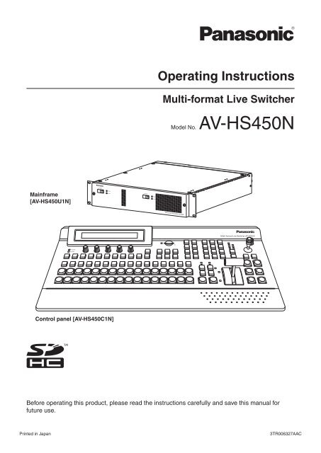
POWERALARMMulti-format Live Switcher AV-HS450<strong>Operating</strong> <strong>Instructions</strong>Multi-format Live SwitcherModel No. AV-HS450NMainframe[AV-HS450U1N]POWER1OFF ONPOWER1ALARM1OFF POWER2 ONPOWER2ALARM2Multi-format Live Switcher AV-HS450Control panel [AV-HS450C1N]Before operating this product, please read the instructions carefully and save this manual forfuture use.Printed in Japan3TR006327AAC
Safety precautionsIMPORTANT SAFETY INSTRUCTIONSRead these operating instructions carefully before using the unit. Follow the safety instructions on theunit and the applicable safety instructions listed below. Keep these operating instructions handy for futurereference.1) Read these instructions.2) Keep these instructions.3) Heed all warnings.4) Follow all instructions.5) Do not use this apparatus near water.6) Clean only with dry cloth.7) Do not block any ventilation openings. Installin accordance with the manufacturer’sinstructions.8) Do not install near any heat sourcessuch as radiators, heat registers, stoves, orother apparatus (including amplifiers) thatproduce heat.9) Do not defeat the safety purpose of thepolarized or grounding-type plug. A polarizedplug has two blades with one wider than theother. A grounding-type plug has two bladesand a third grounding prong. The wide blade orthe third prong are provided for your safety. Ifthe provided plug does not fit into your outlet,consult an electrician for replacement of theobsolete outlet.10) Protect the power cord form being walked on orpinched particularly at plugs, conveniencereceptacles, and the point where they exit fromthe apparatus.11) Only use attachments/accessories specified bythe manufacturer.12) Use only with the cart, stand,tripod, bracket, or table specifiedby the manufacturer, or sold withthe apparatus. When a cart isused, use caution when movingthe cart/apparatus combination toavoid injury from tip-over.13) Unplug this apparatus during lightning stormsor when unused for long periods of time.14) Refer all servicing to qualified servicepersonnel. Servicing is required when theapparatus has been damaged in any way, suchas power-supply cord or plug is damaged,liquid has been spilled or objects have falleninto the apparatus, the apparatus has beenexposed to rain or moisture, does not operatenormally, or has been dropped.indicates safety information.This product contains a CR Coin Cell Lithium Battery which contains Perchlorate Material – special handlingmay apply.See www.dtsc.ca/gov/hazardouswaste.perchlorate.3
ContentsDescription ................................................7Features .....................................................7Configuration ............................................9Accessories ..............................................9Precautions for use ................................10Tra demarks andRegistered Trademarks .....................11Disclaimer of Warranty ...........................111. Installation ...........................................121-1. Installing the control panel...............................121-2. Installing the mainframe ..................................131-3. How to install the option boards ......................141-4. Connections ....................................................161-4-1. Block diagram ...........................................161-4-2. Co nnections when implementing gen-lock(frame synchronizer OFF) ....................171-4-3. Co nnections when not implementing genlock(frame synchronizer ON) ..............182. Functions in each area .......................192-1. Control panel ...................................................192-1-1. Crosspoint area ........................................202-1-2. Wipe pattern/memory area .......................212-1-3. User button area .......................................222-1-4. Transition area ..........................................222-1-5. LCD menu area ........................................252-1-6. Positioner area ..........................................272-1-7. SD memory card area ..............................282-1-8. Rear panel connections area ....................292-2. Mainframe .......................................................302-2-1. Front panel ................................................302-2-2. Rear panel connections area ....................313. Basic operations .................................333-1. Background transition ......................................333-1-1. Selecting the bus ......................................333-1-2. Se lecting the bus using theSHIFT function .....................................333-1-3. Selecting the bus mode ............................363-1-4. Selecting the transition mode ...................373-1-5. Manual transition (using the fader lever) ...373-1-6. Auto transition ...........................................373-1-7. Cut transition .............................................373-2. IMAGE .............................................................383-2-1. Setting the IMAGE effects.........................383-2-2. Executing the IMAGE effect ......................393-3. Wipe ................................................................403-3-1. Selecting the wipe pattern ........................403-3-2. Se lecting the background for the3D2 pattern page .................................423-3-3. Selecting the wipe direction ......................423-3-4. Wipe decorations (border, soft effect) .......433-3-5. Setting the wipe start position ...................443-3-6. Modifying wipe ..........................................453-4. Key ..................................................................473-4-1. Selecting the key type ...............................483-4-2. Selecting the key material .........................493-4-3. Key transitions ..........................................503-4-4. Key preview...............................................513-4-5. Ad justing the luminance keyand linear key .......................................523-4-6. Adjusting the chroma key .........................533-4-7. Key decorations ........................................613-4-8. Masking the key signals ............................623-4-9. Flying key ..................................................633-5. PinP (picture in picture) ...................................643-5-1. Se lecting the PinP channeland material .........................................643-5-2. Selecting Shape........................................653-5-3. PinP preview .............................................653-5-4. PinP transitions .........................................663-5-5. PinP adjustments ......................................663-5-6. Linking PinP1 and PinP2 ..........................683-5-7. PinP decorations .......................................693-5-8. Trimming settings ......................................704
Contents3-6. DSK (downstream key)....................................713-6-1. Selecting the DSK type .............................713-6-2. Se lecting the DSK channel andDSK fill material ....................................733-6-3. DSK transitions .........................................743-6-4. DSK preview .............................................743-6-5. DSK adjustments ......................................753-6-6. DSK decorations .......................................763-6-7. Masking the DSK signals ..........................773-7. FTB (fade to black) ..........................................783-8. Internal color signals .......................................793-8-1. Setting the color background ....................793-9. Switching the AUX output ................................803-9-1. Selecting the AUX output materials ..........803-9-2. AUX1 transitions .......................................813-9-3. Se tting enable/disable for theAUX1 transition.....................................823-10. Memory .........................................................833-10-1. Memory registration and recall items ......843-10-2. St oring the settings in thememory (Store) ...................................853-10-3. R ecalling the operations stored in thememory (Recall)...................................863-10-4. D eleting the operations stored in thememory (Delete) ..................................873-10-5. Effect dissolve .........................................883-11. Frame memories ...........................................893-11-1. Transferring images from the AUX bus ...893-11-2. Saving Images in Flash Memory ............903-12. SD memory cards .........................................913-12-1. Initializing the SD memory cards ............923-12-2. Saving data on SD memory cards ..........933-12-3. Loading data from SD memory cards .....943-12-4. Deleting files on SD memory cards ........953-12-5. Di splaying the SD memory cardinformation...........................................954. Input/output signal settings............... 964-1. Input signal settings.........................................964-1-1. Setting the frame synchronizer .................974-1-2. Setting the input mode ..............................984-1-3. Freezing the input signals .........................994-1-4. Color corrector ........................................1004-1-5. Setting the up-converter .........................1044-1-6. Setting the analog input gain (option).....1054-1-7. Se tting the analog composite input signals(option) ...............................................1064-2. Setting the DVI input signals (option) ............1074-2-1. Setting the DVI input signals ...................1074-2-2. Adjusting the DVI input signals ...............1114-3. Setting the output signals ..............................1124-3-1. Assigning the output signals ...................1134-4. Se tting the DVI output signals(OUT5 and OUT6 standard outputs andoptions) .....................................................1154-5. Setting the down-converter (option) ..............1174-6. Setting the sync signals.................................1184-7. Adjusting the output signal phase .................1194-8. Setting the multi view display ........................1234-8-1. Setting the screen layout ........................1234-8-2. Setting the split frame and characters ....1254-8-3. Setting the tally displays .........................1264-8-4. Changing the material names .................1274-8-5. High-resolution multi view mode .............1284-9. Setting the on-screen display (OSD).............1294-10. Setting the ancillary data .............................1305
Contents5. System settings ................................1315-1. Selecting the video format .............................1315-2. Setting the crosspoints ..................................1325-2-1. Assigning signals to the crosspoints .......1325-2-2. Setting the crosspoint switching .............1345-3. Button assignments .......................................1355-3-1. Setting the user buttons ..........................1355-4. Setting the date and time ..............................1375-5. Network settings ............................................1385-6. Other settings ................................................1395-7. External device control ..................................1405-7-1. En able/Disable Setting for Control ofExternal Devices ................................1405-7-2. Editor control...........................................1415-7-3. Setting the GPI .......................................1425-7-4. Camera control .......................................1445-8. Status displays ..............................................1515-8-1. Alarm status displays ..............................1515-8-2. Alarm message .......................................1515-8-3. Di splaying the version information andoption information ................................1525-9. Initialization....................................................1535-9-1. Initializing Setting Data ...........................1535-9-2. Initializing Fader ......................................1536. External interfaces ...........................1546-1. Co nnecting the control paneland mainframe ..........................................1546-2. Mainframe .....................................................1546-2-1. LAN .........................................................1546-2-2. EDITOR ..................................................1556-2-3. COM .......................................................1556-2-4. TALLY/GPI ...............................................1566-3. Control panel .................................................1576-3-1. TALLY/GPI ...............................................1577. Image transmission functions .........1588. Setting menu table ............................1639. Appearance .......................................18110. Specifications .................................182Appendix (glossary).............................1876
DescriptionThis is a 1 ME digital video switcher which supports a multiple number of HD and SD formats.It consists of a mainframe and control panel.Despite its compact dimensions of 2RU, the mainframe comes with 16 inputs and four outputs for SDI under thestandard specifications.It also supports two DVI outputs, and its video effects of one key line, two DSK lines, two PinP lines, two DVE(BKGD) lines, one DVE (key) line and two multi view lines enable video productions in a wide variety of forms.Incorporated in the switcher’s inputs are a frame synchronizer, up-converter and color corrector.When the option boards are installed, a wider variety of input/output formats including analog composite, analogcomponent and DVI can be accommodated so that systems can be constructed flexibly.FeaturesCompact design, wide variety of input/output signals The mainframe, despite its compact dimensions of 2RU, comes with a wide variety of input/output facilities inthe standard configuration.As input facilities, a total of 16 HD/SD-SDI signal lines are supported under the standard specifications, and aframe synchronizer is incorporated for all the inputs. Also incorporated are four up-converter signal lines andeight color corrector signal lines.The output facilities include four HD/SD-SDI signal lines and two DVI-D signal lines under the standardspecifications. Two option slots each for input/output applications are provided.When two option boards for input applications are installed, the maximum number of input signal lines can beexpanded to 20; similarly, when two option boards for output applications are installed, the maximum number ofoutput signal lines can be increased to 10.Multiple formats supported The signal formats supported include HD formats (1080/59.94i, 1080/50i, 1080/24PsF 1 , 1080/23.98PsF 1 ,720/59.94p and 720/50p), SD formats (480/59.94i and 576/50i) and DVI 2 .1: The following option boards are not supported:AV-HS04M1, AV-HS04M2, AV-HS04M3, AV-HS04M4, AV-HS04M5,AV-HS04M6, AV-HS04M72: The standard DVI output is the DVI-D signal output.The AV-HS04M3 option board supports DVI-I signal input, the AV-HS04M8 option board supports DVI-Dsignal input, and the AV-HS04M5 supports DVI-I signal output.Multi view display function Two multi view display function lines are provided under the standard specifications.It is possible to divide up to 20 lines of video including program video (PGM), preview video (PVW) and inputvideo signals between two screens and display them at the same time on two monitors.Frame synchronizer system and external synchronization system supported A high-performance 10-bit frame synchronizer is incorporated for all the inputs so that asynchronous videosignals can be input. By using the black burst (BB) output, it is possible to construct a system referenced to thesynchronization of the switcher. A genlock function is provided so that external synchronization systems using external sync signals (BB or TRIsignals) as a reference are also supported.7
FeaturesMany different effect functions incorporated Along with the standard wipe, mix and cut functions, the switcher can provide size reduction, slide and otherDVE transitions. DVE transitions using the 2-screen push-out effect and other 2-channel functions are possible. The unit comes with luminance keys and chroma keys provided as keyers as well as specialized hardware inthe form of two DSK lines and two PinP lines as a standard option. AUX1 is equipped with a mix transition function.This enables MIX transitions with the material selected next, allowing for a flexible system construction.High-quality chroma keys using Primatte ® algorithmsThe Primatte ® algorithm, which has proven to be very popular in many non-linear editors as a plug-in software,has been put to practical use in a linear editing system for the chroma keys. High chroma key image quality canbe achieved through some simple operations. Primatte ® is a registered trademark of IMAGICA DIGIX Inc. The copyrights of Primatte ® belong to IMAGICA DIGIX Inc. The patents for Primatte ® belong to IMAGICA DIGIX Inc.SDHC memory cards supported Still image data (BMP, JPEG) can be imported from SDHC memory cards into the unit’s frame memories for useas background images or key materials.In addition, the images and setting data in the unit’s frame memories can be stored on the SDHC memorycards. SDHC Logo is a trademark.Pan-tilt head system (pan-tilt head and convertible camera) control supported Using the COM connector, a <strong>Panasonic</strong> pan-tilt head system (with pan, tilt, zoom, focus and preset functions)can be controlled.When a controller is used, up to five pan-tilt head systems can be controlled.Camera menu operations can also be performed.Controllers supportedPan-tilt heads supportedCamera supportedAW-RP555N, AW-RP655NAW-PH400P, AW-PH405N, AW-PH360NAW-HE100NRedundant power supply Under the standard specifications, a redundant power supply is provided so that live operations can beundertaken with complete peace of mind.Simple operability Live transmissions can be delivered speedily thanks to the 16 crosspoint buttons and pattern selection buttonsand other controls on the panel with its simple layout that enables various functions to be operated directly.Preset-like operations are performed using menus appearing on the unit’s LCD display or on the on-screendisplays.8
ConfigurationMainframe [AV-HS450U1N] .............................................................................. 1Control panel [AV-HS450C1N] .......................................................................... 1Accessories<strong>Operating</strong> instructions ....................................................................................... 1CD-ROM (<strong>Operating</strong> instructions/Image transmission software) ...................... 1AC adapters (for control panel) ......................................................................... 2Power cords (for mainframe and AC adapter) .................................................. 4CAT5E cable (STP, straight cable, 10 m long) .................................................. 1Optional boards (sold separately)Board Model number FunctionSDI Input Board AV-HS04M1 SDI input 2 linesAnalog Input Board AV-HS04M2 Analog component input 2 linesDVI Input Board AV-HS04M3 DVI-I input 2 linesAnalog Output Board AV-HS04M4 Analog component output 2 linesDVI/Analog Output Board AV-HS04M5 DVI-I output 1 lineAnalog component output 1 lineAnalog Composite Input Board AV-HS04M6 Analog composite input 2 linesSDI Output Board AV-HS04M7 SDI output 2 linesFull-HD DVI Input Board AV-HS04M8 DVI-D input 2 line Option boards are installed in the two input/output option slots (slot A, slot B).9
Precautions for use Handle carefully.Do not drop the product, or subject it to strong shock or vibration.Do not carry or move the product by the fader lever. This is important to prevent trouble. Use the product in an ambient temperature of 32 °F to 104 °F (0 °C to 40 °C).Avoid using the product at a cold place below 32 °F (0 °C) or at a hot place above 104 °F (40 °C) becauseextremely low or high temperature will adversely affect the parts inside. Power off before connecting or disconnecting cables.Before plugging or unplugging the cables, be sure to switch power off. Avoid humidity and dust.Avoid using the product at a humid, dusty place because much humidity and dust will cause damage to theparts inside. MaintenanceWipe the product using a dry cloth. To remove stubborn dirt, dip a cloth into a diluted solution of kitchendetergent (neutral), wring it out well, and wipe the product gently. Then, after wiping the product with a moistcloth, wipe it again with a dry cloth.Caution• Avoid using benzine, paint thinners and other volatile fluids.• If a chemical cleaning cloth is to be used, carefully read through the precautions for its use. Precaution to be observed during productionThis product’s image switching and image effect functions can be used to produce images which flicker rapidlyor images which change rapidly.However, bear in mind when using these functions in production that the kinds of images produced may havean adverse effect on the viewer’s physical well-being. Handling the optional boardsBe absolutely sure to turn off the power of the product before installing or removing any of the optional boards.Furthermore, when installing or removing the optional boards, take care not to hurt yourself on the edges andmetal parts of the boards. When the product is to be discardedWhen the product is to be discarded at the end of its service life, ask a specialized contractor to dispose of itproperly in order to protect the environment. Concerning the consumable partsCooling fan:This is a consumable part. As a general rule, replace it every 5 years or so (when the unit has beenoperated for 15 hours a day).Power supply unit:This is a consumable part. As a general rule, replace it every 5 years or so (when the unit has beenoperated for 15 hours a day).The period when the consumable parts need to be replaced will differ depending on the operating conditions.When the time comes to replace one of these parts, be absolutely sure to ask your dealer to do the job.10
Precautions for useTrademarks and Registered Trademarks Microsoft and Windows are either registered trademarks or trademarks of Microsoft Corporation in the UnitedStates and other countries. Adobe and Reader are either registered trademarks or trademarks of Adobe Systems Incorporated in theUnited States and/or other countries. SDHC logo is a trademark. Other names of companies and products contained in these operating instructions may be trademarks orregistered trademarks of their respective owners.Disclaimer of WarrantyIN NO EVENT SHALL <strong>Panasonic</strong> Corporation BE LIABLE TO ANY PARTY OR ANY PERSON, EXCEPT FORREPLACEMENT OR REASONABLE MAINTENANCE OF THE PRODUCT, FOR THE CASES, INCLUDING BUTNOT LIMITED TO BELOW:ANY DAMAGE AND LOSS, INCLUDING WITHOUT LIMITATION, DIRECT OR INDIRECT, SPECIAL,CONSEQUENTIAL OR EXEMPLARY, ARISING OUT OF OR RELATING TO THE PRODUCT;PERSONAL INJURY OR ANY DAMAGE CAUSED BY INAPPROPRIATE USE OR NEGLIGENTOPERATION OF THE USER;UNAUTHORIZED DISASSEMBLE, REPAIR OR MODIFICATION OF THE PRODUCT BY THE USER;INCONVENIENCE OR ANY LOSS ARISING WHEN IMAGES ARE NOT DISPLAYED, DUE TO ANYREASON OR CAUSE INCLUDING ANY FAILURE OR PROBLEM OF THE PRODUCT;ANY PROBLEM, CONSEQUENTIAL INCONVENIENCE, OR LOSS OR DAMAGE, ARISING OUT OF THESYSTEM COMBINED BY THE DEVICES OF THIRD PARTY;INCONVENIENCE, DAMAGE, OR LOSS RESULTING FROM ACCIDENTS CAUSED BY AN INADEQUATEINSTALLATION METHOD OR ANYTHING OTHER THAN A DEFECT IN THE PRODUCT;LOSS OF REGISTERED DATA CAUSED BY ANY FAILURE.ANY DAMAGE OR CLAIMS DUE TO LOSS OR LEAKAGE OF IMAGE DATA OR SETTING DATA SAVEDON THIS UNIT OR ON AN SD CARD OR PC.11
POWERALARMMulti-format Live Switcher AV-HS4501. Installation1-1. Installing the control panelFollow the instructions set forth in “Safety precautions” and also observe thecautionary items below.Be absolutely sure to ask your dealer to do the jobs of installing and connecting the panel.Connecting the power supply Be absolutely sure to use only the power cord and AC adapter supplied with thepanel. Be absolutely sure to connect the grounding terminal of the power cord toground.Also connect the ground terminal (SIGNAL GND) at the rear of the panel to thesystem ground. If only one AC adapter is to be connected, place the dust-proof cap over the DCpower input socket that is not going to be used. To prevent the DC plug from being disconnected, secure the cable of the ACadapter to the cable clamp. When the control panel is not going to be used for a prolonged period of time,set its power switch to the “off” position to conserve power, and disconnect thepower plug.Dust-proof capMAINFRAMELCD CONTRAST12V IN1 12V IN2POWERON OFFCable clampHandle the control panel carefully! Dropping the control panel or subjecting it to strong impact or vibration may cause trouble and/or malfunctioning.Do not allow any foreign objects to enter inside the control panel! Allowing water, metal items, scraps of food or other foreign objects inside the control panel may cause a fireand/or electric shocks.Choosing the best installation location This unit is designed for indoor use only. Install the unit on a sufficiently strong, stable and levelsurface for use. Ensure a space of at least 100 mm around the rearvents to avoid obstructing ventilation.In particular, ensure sufficient space betweenventilation and wiring when using mounted in a panelor table. Do not install the panel in a cold place where thetemperatures will drop below 32 °F (0 °C) or in a hotplace where the temperatures will rise above 104 °F(40 °C). Avoid installing the panel where it will be exposed todirect sunlight or to the hot air that is blown out fromother products. Installing the panel in a very humid, dusty or vibrationpronelocation may give rise to trouble.Ventilation holes12
POWER1O F ONPOWER1ALARM1O F POWER2 ONPOWER2ALARM21. Installation1-2. Installing the mainframeComply with the instructions set forth in “Safety precautions” and also observethe cautionary items below.Be absolutely sure to ask your dealer to do the jobs of installing and connecting the mainframe.Connecting the power supply Be absolutely sure to use the power cord supplied with the mainframe. Be absolutely sure to connect the grounding terminal of the power cord to ground.Handle the mainframe carefully! Dropping the mainframe or subjecting it to strong impact or vibration may cause trouble and/or malfunctioning.Do not allow any foreign objects to enter inside the mainframe! Allowing water, metal items, scraps of food or other foreign objects inside the control panel may cause a fireand/or electric shocks.Choosing the best installation location This unit is designed for indoor use only. Mount the mainframe securely in a standard 19-inch rack (with a depth dimension of at least 600 mm) thatmeets the EIA standard or its equivalent for use. Install the mainframe securely using screws that are compatible with the rack. Be absolutely sure to attach the support guides used to support the back part of the mainframe. (Providesupport guides that are compatible with the rack.) Provide sufficient clearances from the area around the ventilation holes at the front and the cooling fan at theback. Do not install the mainframe in a cold place where the temperatures will drop below 32 °F (0 °C) or in a hotplace where the temperatures will rise above 104 °F (40 °C). Avoid installing the mainframe where it will be exposed to direct sunlight or to the hot air that is blown out fromother products. Installing the mainframe in a very humid, dusty or vibration-prone location may give rise to trouble.Support guidesMulti-format Live Switcher AV-HS450O F POWER2 ONPOWER2ALARM2Multi-format Live Switcher AV-HS450POWER1O F ONPOWER1ALARM1Installation in a rackFlow of air through the ventilation holes13
1. Installation1-3. How to install the option boardsThe option boards are installed in the mainframe.For details, refer to the operating instructions of the option board concerned.Notes Be absolutely sure to ask your dealer to do the job of installing or removing the option boards. Before installing or removing an option board, turn off the power, and disconnect the power plug. Before coming into physical contact with the option board, touch your hand to metal that has been groundedto discharge the static electricity in your body.A safe way to proceed is to wear an anti-static wrist strap.The option board may be damaged if you touch the board with static still in your body. Avoid damage to the option board by not dropping it or subjecting it to strong shocks or vibrations. After removing an option board, be absolutely sure to attach the blank panel. When installing or removing an option board, take care not to hurt yourself on the edges or metal parts of theboard.Turn off the power of the mainframe, and disconnect the power cord.Loosen the two screws of SLOT A or SLOT B at the back of the mainframe, and remove the blank panel.SLOT ASLOT BBlank panelScrewScrew14
1. InstallationAlign the option board with the guide rails, and insert it slowly.Insert it until it will go no further. Take care not to exert excessive force while doing this since that may damagethe connector inside.Mount the option board in place using the two screws.Clamping torque: 0.7 N•mDV INPUTSDVI-D DVI-DScrewScrewAfter connecting the necessary cables, plug the power cord into the power outlet, and turn on the power.15
1. Installation1-4. Connections1-4-1. Block diagramMainframeINPUT (SDI)1 to 16INPUT1 to 8INPUT9 to 12INPUT13 to 16FSFSCCFSUCCCBlackColorBGDColorBarFMEM1 to 4MTXBKGDCUT, MIX, WIPE, DVE2KEYCUT, MIX, WIPE, DVEPinP1, 2MIXDSK1, 2MIXFTBAUX1 to 4MV1, 2OutputMTXOUTPUT1 to 4OUTPUT5, 6OUTPUT (SDI)1 to 4 (3)OUTPUT (DVI-D)5, 6INPUTA1, A2Option slot AOUTPUTA1, A2INPUTB1, B2Option slot BOUTPUTB1, B2AC INAC/DCPowerREF IN/OUT (1)REFAC/DCREF OUT (2)PCDC INAC/DCAC/DCRJ45LAN(5)SDmemorycardPANEL(4)MAINFRAMEControl panelPowerRJ45 Dsub 50 Dsub 9 Dsub 9ALARM: 1GPI-OUT: 31GPI-IN: 8TALLY/GPIALARM: 1GPI-OUT: 8GPI-IN: 8TALLY/GPIRJ45 Dsub 25EDITORCOM Camera Pan/Tilt Head ControllerEditingcontrollerAux panel1: When external synchronization is selected as thereference signal setting, the reference signal is input.When internal synchronization is selected, the referencesignal is output.2: When external synchronization is selected as thereference signal setting, the signals are looped throughand output. When internal synchronization is selected, thereference signal is output.3: Two sets of the same output signals are distributed fromOUTPUT (SDI) 1.4: Connect the PANEL connector directly to theMAINFRAME connector using the supplied CAT5E cable.5: Do not connect to a public line when connecting a PC.16
11 234 5 6 7 8 9 10 11 12 13 14 15 16 C/C2 3 4 5 6U/CTALLY / GPISERVICENORMALMAINFRAMELCD CONTRAST12V IN 1SIGNALGND12V IN 2POWERON OFF1. Installation1-4-2. Connections when implementing gen-lock(frame synchronizer OFF)Sync GeneratorHD cameraHD cameraHD SDIHD SDIVTRHD SDIHD cameraHD SDISLOT AIN/OUT A1IN/OUT A2SLOT BIN/OUT B1IN/OUT B2 IN1SDI INPUTSSDI OUTPUTSDVI-D OUTPUTSEDITORREFSIGNALGND IN2LANPANELTALLY/GPICOMHD SDI monitorHD SDIMulti-format LiveSwitcherAV-HS450NPower cordHD SDIHD SDI monitorDVI-DPC monitorAC adapterDVI-DPC monitor When the unit is to be installed and when the connections are to be performed, be absolutelysure to ask your dealer to be responsible for carrying out the work that needs to be done. Use a 3-point power outlet as the power source in order to earth the unit securely.17
11 234 5 6 7 8 9 10 11 12 13 14 15 16 C/C2 3 4 5 6DVI-DDVI INPUTSDVI-DU/CTALLY / GPISERVICENORMALMAINFRAMELCD CONTRAST12V IN 1SIGNALGND12V IN 2POWERON OFF1. Installation1-4-3. Connections when not implementing gen-lock(frame synchronizer ON)Example where the optional board is usedSLOT A: Analog Input Board (AV-HS04M2)SLOT B: Full-HD DVI Input Board (AV-HS04M8)PCHD ComponentHD cameraDVI-DPCDVD playerHD ComponentDVI-DVTRHD SDISD SDIHD cameraSLOT AYIN/OUT A1IN/OUT A2ANALOG INPUTSPb Pr Y Pb PrSLOT BIN/OUT B1IN/OUT B2 IN1SDI INPUTSSDI OUTPUTSDVI-D OUTPUTSEDITORREFSIGNALGND IN2LANPANELTALLY/GPICOMHD SDI monitorHD SDIMulti-format LiveSwitcherAV-HS450NPower cordHD SDIHD SDI monitorDVI-DPC monitorAC adapterDVI-DPC monitor18
2. Functions in each area2-1. Control panelUser button areaWipe pattern/memory areaLCD menu areaSD memory card areaPositioner areaMulti-format Live Switcher AV-HS450SHOTMEMBKGDWIPEMEMSTORRECALL1 231 2 345 6PAGEWIPESQ1 SQ2SL1 SL2ZPOWER4 5 63D1 3D2ALARMKEY PinP1CKEY PinP2F1 F2 F3 F4 F5DSK1 TIMEIMAGE A FMEM CTL XPTBKGDDSK2 CBGDIMAGE B SDCard CAM MVINOUTHOLDCONFIGSYS1 2 3PinPMEMCAMMEMDELUNDO7 8 97 8 910 1112BKGDPATTKEYPATTPOSITIONERN/R RAUXKEY PinP 1/2 DSK 1/2 AUX1 AUX2 AUX3 AUX4AMBER:1 / GREEN :2MENU FUNCTION / AUX BUS DELEGATION4 5 6USERSHIFT10 XPT DSBL EFF DSLVMEMORY / PATTERNMIXWIPEWIPE DIRECTIONKEY FTBON ONBKGDKEYONPGM/ASHIFTMIXWIPEPinP1ONPinP2ON1/17 2/18 3/19 4/20 5/21 6/22 7/23 8/24 9/25 10/26 11/27 12/28 13/29 14/30 15/31 16/32PST/BSHIFTCUTAUTODSK1ONDSK2ONCrosspoint areaTransition area Power indicator [POWER]This indicator lights when the power switch () on the rear panel is set to ON while power is supplied to theDC power input socket.It goes off when the power switch () is set to OFF. Alarm indicator [ALARM]This indicator lights when the mainframe’s cooling fan has stopped running or when there is a problem (voltagedrop) with the power supply of the mainframe or the control panel.When this occurs, an alarm message is displayed on the LCD and on the OSD screen of the external monitor.During the occurrence of an alarm, details of the trouble can be checked using the SYSTEM/Alarm menu.Alarm information can be output to an external device from the control panel’s TALLY/GPI connector (). For details, refer to “5-8-2. Alarm message”.If the alarm goes off, stop using the unit immediately and be sure to contact your dealer.Continuing to use the unit even after the alarm goes off could damage it.19
2. Functions in each area2-1-1. Crosspoint areaKEY PinP1 DSK1 TIMEIMAGE A FMEM CTLBKGDCKEY PinP2 DSK2 CBGDIMAGE B SDCard CAMXPTMVINOUTCONFIGSYS1 2 3CAMMEMAUXKEY PinP 1/2 DSK 1/2 AUX1 AUX2 AUX3 AUX4AMBER:1 / GREEN :2MENU FUNCTION / AUX BUS DELEGATION4 5 6USERSHI<strong>FTP</strong>GM/ASHI<strong>FTP</strong>ST/B1/17 2/18 3/19 4/20 5/21 6/22 7/23 8/24 9/25 10/26 11/27 12/28 13/29 14/30 15/31 16/32SHIFT PGM/A bus crosspoint buttons [PGM/A 1 to 32]These are used to select the PGM/A bus video signals.Buttons 1 to 32 can be selected using the [SHIFT] button. Refer to “3-1-2. Selecting the bus using the SHIFT function”.In the case of the flip-flop system, the main line video (PGM) signals are always selected.When one of the crosspoint buttons (, , ) is held down, the name of the input material and the number ofthe crosspoint button are displayed. PST/B bus crosspoint buttons [PST/B 1 to 32]These are used to select the PST/B bus video signals.Buttons 1 to 32 can be selected using the [SHIFT] button. Refer to “3-1-2. Selecting the bus using the SHIFT function”.In the case of the flip-flop system, the images inserted next (PST) are always selected. AUX bus selector buttons [KEY, PinP 1/2, DSK 1/2, AUX1 to AUX4]Select the bus to be operated using the AUX bus crosspoint buttons ().The selected button lights.[KEY]:This button is used to change the AUX bus crosspoint buttons () into the selector buttons for the sourcesof the key fill buses.The source for the key source bus can be set using the menu displayed when the AUX bus crosspointbuttons () are held down. The set source will be the same for DSK1 and DSK2.The source can also be set from the CONFIG menu.[PinP 1/2]:This button is used to change the AUX bus crosspoint buttons () into the selector buttons for the sourcesof the PinP buses.Each time it is pressed, its target is switched between PinP1 and PinP2.When PinP1 is selected, the button lights in amber; when PinP2 is selected, it lights in green.[DSK 1/2]:This button is used to change the AUX bus crosspoint buttons () into the selector buttons for the sourcesof the DSK fill buses.Each time it is pressed, its target is switched between DSK1 and DSK2.When DSK1 is selected, the button lights in amber; when DSK2 is selected, it lights in green.[AUX1] - [AUX4]:These buttons are used to change the AUX bus crosspoint buttons () into the selector buttons for thesources of the AUX buses.The AUX bus selector buttons are also used as the menu function buttons ().20
2. Functions in each area AUX bus crosspoint buttonsThese buttons are used to select the source of the bus which was selected by the AUX bus selector button ().Buttons 1 to 32 can be selected using the [SHIFT] button. Refer to “3-1-2. Selecting the bus using the SHIFT function”.2-1-2. Wipe pattern/memory area Wipe pattern and memory selector buttonsWipe patterns 1 to 12 can be selected while the BKGD and KEYpattern selector buttons () are lighted.Data can be stored in the memories of buttons 1 to 10 orrecalled from these memories while one of the memoryoperation buttons () — [SHOT MEM], [BKGD WIPE MEM],[PinP MEM] or [CAM MEM] — is lighted.SHOTMEMBKGDWIPEMEMPinPMEMCAMMEM STORRECALLDELUNDO1 241 2 34 5 67 8 910 XPT DSBL EFF DSLV35 67 8 910 1112MEMORY / PATTERN BKGD, KEY pattern selector buttons [BKGD PATT] [KEY PATT]Press the [BKGD PATT] button, and while it is lighted, select the wipe pattern for the background transition.Similarly, press the [KEY PATT] button, and while it is lighted, select the wipe pattern for the key transition.Each time the [BKGD PATT] button and [KEY PATT] button are pressed, the pattern page changes in thefollowing sequence: WIPE, SQ1 (squeeze 1), SL1 (slide 1), 3D1 (3 dimensions 1), SQ2 (squeeze 2), SL2(slide 2) and 3D2 (3 dimensions 2). Which pattern page has been selected can be checked by observing whichpattern page indicator LED () is lighted.SQ2, SL2, and 3D2 may not be selected as the wipe pattern for the key transition. Pattern page indicator LEDs [PAGE]By observing which pattern page indicator LED is lighted, it is possible to check which pattern page has beenselected by the BKDG PATT or KEY PATT selector button (). Memory operation buttons [SHOT MEM] [BKGD WIPE MEM] [PinP MEM] [CAM MEM][STOR] [RECALL] [DEL] [UNDO]Press the [SHOT MEM], [BKGD WIPE MEM], [PinP MEM] or [CAM MEM] button to perform the memoryoperations for the number keys (1 to 10).[STOR]:Press this to register data in the memory.[RECALL]:Press this to recall data from the memory.[DEL]:Press this to delete data in the memory.[UNDO]:Press this to undo the operation of the [RECALL] or [DEL] button.The number of operations that can be undone is one only.This operation cannot be performed using memory operations when the [CAM MEM] button has beenpressed.PAGEWIPESQ1SL13D1SQ2SL23D2BKGDPATTKEYPATT21
2. Functions in each area2-1-3. User button area User buttons [USER1 to USER6]These are used to assign some functions of the menu settings to the [USER1]to [USER6] buttons on the CONFIG menu. See “5-3-1. Setting the user buttons”.1 2 34 5 6USER2-1-4. Transition areaUNDO8 910 111210 XPT DSBL EFF DSLVMEMORY / PATTERNMIXWIPEKEYPATTN/RKEYONRWIPE DIRECTIONFTBONBKGDMIXCUTKEYONWIPEAUTOPinP1ONDSK1ONPinP2ONDSK2ON [BKGD] buttonThis executes the background transition when the [AUTO] button () or fader lever () has been operated.When the [BKGD] button is pressed and it is selected, its indicator lights in amber.If the [KEY] button () is now pressed, the indicator goes off, and the de-selected status is established.When the [BKGD] button and [KEY] button () are pressed at the same time, both buttons are set to theselected status. [KEY] buttonThis executes the key transition when the [AUTO] button () or fader lever () has been operated.When the [KEY] button is pressed and it is selected, its indicator lights in amber.If the [BKGD] button () is now pressed, the indicator goes off, and the de-selected status is established.When the [BKGD] button () and [KEY] button are pressed at the same time, both buttons are set to theselected status. KEY ON tally LEDThis lights in red when the key ON status is established. MIX, WIPE selection status tally LEDsThese light up to indicate whether MIX or WIPE has been selected when background transitions or keytransitions are executed.22
2. Functions in each area [MIX] buttonThis is used to switch the A and B bus images while making them overlap.During the transition, the A and B bus output total is kept at 100 %.When the [MIX] button is pressed and it is selected, its indicator lights in amber.If the [WIPE] button () is now pressed, it goes off, and the de-selected status is established. [WIPE] buttonThis is used to execute the transition using the pattern selected by the wipe pattern selector button ().When the [WIPE] button is pressed and it is selected, its indicator lights in amber.If the [MIX] button () is now pressed, it goes off, and the de-selected status is established. [AUTO] buttonThis is used to automatically execute transitions (auto transition) using the transition time which has been seton the TIME menu.During auto transition its indicator lights in amber. When the button is pressed again during auto transition, theauto transition operation is suspended, and the indicator lights in green. When it is pressed again while autotransition is suspended, the remaining transition is executed.The indicator goes off when auto transition is completed.When the [AUTO] button is pressed while the fader lever () is at an interim setting, the transition is executedin the time remaining from the interim setting. [CUT] buttonThis button is used to execute transitions instantly.Its indicator lights in amber during a transition, and it goes off when the transition is completed. [KEY ON] buttonThis button is used to execute the key transition for the transition time which has been set on the TIME menu. [FTB ON] buttonThis button is used to execute fade-out to a black screen or fade-in from a black screen for the transition timewhich has been set on the TIME menu. PinP button [PinP1 ON] [PinP2 ON]This button is used to execute fade-in or fade-out of the picture in picture for the transition time which has beenset on the TIME menu. DSK button [DSK1 ON] [DSK2 ON]This button is used to execute fade-in or fade-out of downstream key for the transition time which has been seton the TIME menu.23
2. Functions in each area Wipe direction selection buttons [WIPE DIRECTION N/R, R]These buttons are used to select the direction in which to wipe for executing background transitions.When the [R] indicator is off:Wiping proceeds in the normal direction.When the [R] indicator is lighted:Wiping proceeds in the reverse direction.When the [N/R] indicator is lighted:The normal direction is replaced with the reverse direction (or vice versa) when the transition iscompleted. (The lighted and extinguished statuses of the [R] button are also switched in line with thedirection of the wiping.) Fader leverThis is used to execute background or key transitions. When it is moved as far as it will go, the transitionis completed. When it has been operated during auto transition, auto transition will be switched to manualoperation as soon as the fader position overtakes the amount of the transition being executed. Bus tally LEDsThese indicate the output statuses of the A bus and B bus. The LED corresponding to the bus whose programsignals (PGM) are being output lights.24
2. Functions in each area2-1-5. LCD menu areaPOWERALARMF1 F2 F3 F4 F5HOLDKEY PinP1 DSK1 TIMEIMAGE A FMEM CTLBKGDCKEY PinP2 DSK2 CBGDIMAGE B SDCard CAMKEY PinP 1/2 DSK 1/2 AUX1 AUX2 AUX3 AUX4AMBER:1 / GREEN :2MENU FUNCTION / AUX BUS DELEGATIONXPTMVINOUTCONFIGSYS LCDThe setting menu is displayed when one of the menu function buttons () is pressed.When the buttons listed below are double-clicked, the specified menu is selected. (The menu delegationfunction)The operation corresponding to the button pressed is also executed.ButtonTransition area BKGD TIME menu/BKGD sub menuKEY TIME menu/KEY sub menuWIPE BKGD menu/Border sub menuWipe pattern area WIPE #5 BKGD menu/WIPEPos sub menu(BKGD)WIPE #5 KEY menu/WIPEPos sub menu(KEY)WIPE #11 BKGD menu/WIPEPos sub menu(BKGD)WIPE #11 KEY menu/WIPEPos sub menu(KEY)SQ #5 BKGD menu/SQPos sub menu(BKGD)SQ #5 KEY menu/SQPos sub menu(KEY)SL #5 KEY menu/FlyKEY sub menu(KEY)Menu25
2. Functions in each area Menu function buttons [MENU FUNCTION/AUX BUS DELEGATION]These are used to select the menus organized by function.Each time one of these buttons is pressed, the menu for its function is switched between the one displayedabove and the one displayed below. Each time the [PinP1/PinP2] button or [DSK1/DSK2] button is pressed, thecolor used for their lighting is switched between amber and green. The other buttons light in amber. Rotary encoders [F1] to [F5]These are used to set the parameters displayed on the menus (LCD screen or on-screen display).For details on the operations, refer to the sections in “3. Basic operations”.[F1]: Rotate this rotary encoder to switch the sub menu.[F2]:On the INPUT menu or OUTPUT menu, the signal to be set is switched.Turn this rotary encoder to set the parameters.On the INPUT menu or OUTPUT menu, the third menu is switched.[F3] to [F5]: Rotate these rotary encoders to set the parameters.When the down arrow (↓) is shown at a menu item, its parameter is set by pressing the corresponding rotaryencoder.When the parameter is one which is set using a numerical value, its default will be restored when the rotaryencoder is held down.(However, the network settings and the date and time settings will not be returned to the defaults.)Basic menu operationsFor detailed operations, refer to the sections in “3. Basic operations”.For the menu configurations, refer to “8. Setting menu table”.Select the menus organized by function using the menu function buttons ().Using the rotary encoders (), display the sub menu that will be used to establish the detailed settings,and set the parameters.Parameter setting areaThird menuSub menuKEY 2|Clip |Gain |Density|InvertAdjust | 0.0| 100.0| 100.0| OffOperate hereusing [F1].Operate hereusing [F2].Operate hereusing [F3].Operate hereusing [F4].Operate hereusing [F5]. The INPUT menu and OUTPUT menu differ depending on whether an option board has been installed. [HOLD] buttonIf the [HOLD] button is pressed while a menu is displayed, no other menu will be selected even when a menufunction button () is pressed.In addition, even if the AUX bus selection button () is pressed it will not switch to another bus.While the [HOLD] button is held down, it lights in amber.26
2. Functions in each area2-1-6. Positioner area Positioner [X/Y]These are used when performing the settings below. PinP1, PinP2 position settings Wipe start position setting (WIPE #5, WIPE #11, SQ #5) Camera control Flying key position setting Chroma key marker position settingPOSITIONERZIn each case, the settings take effect only when the following menu items have been selected.NoteThe center values of the positioner are set during the time it takes for the unit to start up after its power isturned on. Do not operate the positioner until after the switcher has started up. Rotary encoder [Z]This is used to set the PinP size, flying key size or to select the chroma key area.In each case, the settings take effect only when the following menu items have been selected.PositionerRotary encoderX/Y Z SwitchPinP1, PinP2 Position adjustments Size adjustments(size increased by rotatingthe encoder clockwiseand reduced by rotating itcounterclockwise)WIPE (BKGD)WIPE (KEY)Chroma keyRotation angleadjustments(X-direction andY-direction rotation)Start positionadjustmentsStart positionadjustmentsSelection positionadjustmentsRotation angleadjustments(Z-direction rotation)Hold switch down torestore initial values(X/Y, Z).Hold switch down torestore initial values(X/Y, Z).— Hold switch down torestore initial values(X/Y).— Hold switch down torestore initial values(X/Y).Selected area sizeadjustments(size increased by rotatingthe encoder clockwiseand reduced by rotating itcounterclockwise)Flying key Position adjustments Size adjustments(size increased by rotatingthe encoder clockwiseand reduced by rotating itcounterclockwise)Camera controlX: Pan control or focuscontrolY: Tilt control or zoomcontrolExecute samplingHold switch down torestore initial values(X/Y, Z).— Switching betweenpan/tilt control andzoom/focus controlValid menuAll PinP1 and PinP2menus (except forPinP1, PinP2/Rotation)PinP1, PinP2/RotationBKGD/WIPEPosBKGD/SQPosKEY/WIPEPosKEY/SQPosCHR KEY/Sample1CHR KEY/Sample2KEY/FlyKEYAll menus other thanthose listed above27
2. Functions in each area2-1-7. SD memory card area SD memory card slotInsert an SD memory card (purchased separately) or an SDHC memory card(purchased separately) into this slot. SD memory card access LEDThis LED lights while the data on the SD memory card is being accessed.Do not turn off the unit’s power or eject the SD memory card while the access LED is lighted.Doing so can damage the data on the SD memory card.Concerning the recommended SD memory cards and SDHC memory cardsUse of the following SD memory cards and SDHC memory cards made by <strong>Panasonic</strong> is recommended:SDHC memory cards RP-SDM04G, RP-SDM06G, RP-SDM08G,RP-SDM12G, RP-SDM12GRP-SDV04G, RP-SDV08G, RP-SDV16G,RP-SDV32GSD memory cards RP-SD128B, RP-SD256BRP-SDR512RP-SDM01G, RP-SDM02GRP-SDV512, RP-SDV01G, RP-SDV02G28
2. Functions in each area2-1-8. Rear panel connections areaLCD CONTRASTTALLY / GPISERVICENORMALMAINFRAME12V IN 112V IN 2POWERONOFFSIGNALGND TALLY/GPI input/output connector [TALLY/GPI] (D-sub 25-pin, female, inch screw) For details on how to connect this connector, refer to “6. External interfaces”. MAIN FRAME connector [MAIN FRAME] (RJ-45) (100 Base-TX)Connect this to the mainframe using the supplied CAT5E cable (STP, straight, 10 m). DC power input sockets [12V IN1], [12V IN2] (DC 12 V, 0.8 A)Connect the supplied AC adapters (for the control panel) to these sockets. Ground connector [SIGNAL GND]Connect to the system’s earth ground. Power switch [POWER]This is used to turn the power on and off. SERVICE switch [NORMAL/SERVICE]This switch is used for maintenance purposes.For normal operations, select the “NORMAL” position. LCD CONTRAST adjustment screwThis is used to adjust the contrast of the LCD display.29
2. Functions in each area2-2. Mainframe2-2-1. Front panelPower supply 1 Power supply 2POWER1OFF ONPOWER1ALARM1OFF POWER2 ONPOWER2ALARM2Multi-format Live Switcher AV-HS450 Power switch [POWER1, POWER2]These are used to turn the power on and off.As a standard feature, this mainframe has a redundant power supply system.To turn off the power, set the power switches of both system 1 (POWER1) and system 2 (POWER2) to OFF. Power indicator [POWER1, POWER2]This indicator lights when the power switch () is set to ON while power is supplied to the AC power inputsocket.It goes off when the power switch () is set to OFF. Alarm indicator [ALARM1, ALARM2]These light when the mainframe’s cooling fan has stopped running or when there is a problem (voltage drop)in the power supply. When this occurs, an alarm message is displayed on the control panel’s LCD and on theOSD screen of the external monitor.During the occurrence of an alarm, details of the trouble can be checked using the SYSTEM/Alarm menu.The alarm information can be output to an external device from the TALLY/GPI connector () of the mainframe. For details, refer to “5-8-2. Alarm message”.If the alarm goes off, stop using the unit immediately and be sure to contact your dealer.Continuing to use the unit even after the alarm goes off could damage it.30
2. Functions in each area2-2-2. Rear panel connections area SLOT AIN/OUT A1IN/OUT A2SLOT BIN/OUT B1IN/OUT B2 IN1SDI INPUTS1 234 5 6 7 8 9 10 11 12 13 14 15 16 C/CSDI OUTPUTS1DVI-D OUTPUTS2 3 4 5 6U/CEDITORREFSIGNALGND IN2LANPANELTALLY/GPICOM SDI signal input connectors [SDI INPUTS 1 to 16]9 to 16: The color collector function can be used.13 to 16: The up-converter function can be used. Option slot [SLOTA] (IN/OUT A1, IN/OUT A2) Option slot [SLOTB] (IN/OUT B1, IN/OUT B2)Each of these is an input/output option slot.A DVI input board, analog output board or other option board can be installed in these slots.For details, refer to “1-3. How to install the option boards” and the operating instructions of the boardconcerned. SDI signal output connectors [SDI OUTPUTS 1 to 4]1 to 4: These can be allocated by the menus. Two sets of the same output signals are distributed from the OUTPUT1 connector. DVI-D output connectors [DVI-D OUTPUTS 5, 6]These can be allocated by the menus. The DVI-I connector cable cannot be used. Reference input connector/BB outputconnector [REF]Loop-through output in the external sync mode.If the loop-through output is not going to be used,provide a 75-ohm termination.BB signals output from both connectors in the internalsync mode.REFExternal synchronization signal inputLoop-through outputInput the external synchronization signal to the upper ofthe two connectors shown above. PANEL connector [PANEL] (RJ-45) (100 Base-TX)Connect this to the control panel using the supplied CAT5E cable (STP, straight, 10 m).31
2. Functions in each area LAN connector [LAN] (RJ-45) (10/100 Base-TX) For details on how to connect this connector, refer to “6. External interfaces”. EDITOR connector [EDITOR] (RS-422, D-sub 9-pin, female, inch screw COM connector [COM] (RS-422, D-sub 9-pin, female, inch screw) For details on how to connect this connector, refer to “6. External interfaces”. TALLY/GPI input/output connector [TALLY/GPI] (D-sub 50-pin, female, inch screw) For details on how to connect this connector, refer to “6. External interfaces”. Ground connector [SIGNAL GND]Connect to the system’s earth ground. AC power input socket [ IN1] [ IN2] (AC 100 V to 120 V, 50/60 Hz)Connect one end of the supplied power cable to this socket and the other end to the AC outlet.The supplied power cable comes with a 3-pin power plug. Be absolutely sure to plug it into a 3-point poweroutlet as the power source in order to earth the unit securely.If a 3-point power outlet is not available for this connection, be absolutely sure to consult your dealer. Cooling fan32
3. Basic operations3-1. Background transition3-1-1. Selecting the busPress one of the crosspoint buttons to select the material to be used for the background transition. Depending onthe operating status, the button pressed will light in one of two colors.Lighting in red: When the selected input signals are output to PGM.(However, the indicator lights in amber during FTB operations.)Lighting in green: When the selected input signals are not output to PGM.AUXSHI<strong>FTP</strong>GM/ASHI<strong>FTP</strong>ST/B1/17 2/18 3/19 4/20 5/21 6/22 7/23 8/24 9/25 10/26 11/27 12/28 13/29 14/30 15/31 16/32SHIFTLighting in redLighting in greenFurthermore, when one of the crosspoint buttons is held down, the name of the input material and number of thebutton corresponding to the pressed button are displayed on the LCD.3-1-2. Selecting the bus using the SHIFT functionThe SHIFT function enables two materials to be allocated — the front material and the rear material — to onebutton, and the materials to be selected using the [SHIFT] button.A total of 32 materials — front materials (1 to 16) and rear materials (17 to 32) — can be allocated to the threegroups of 16 crosspoint buttons whether these buttons are the PGM/A bus crosspoint buttons, PST/B buscrosspoint buttons or AUX bus crosspoint buttons.There are actually two SHIFT functions: “All SHIFT” for switching all the front materials to the rear materials orvice versa, and “Single SHIFT” for switching the front material of one crosspoint button with its rear material orvice versa.“All SHIFT” works once the SHIFT function has been allocated to one of the USER buttons.“Single SHIFT” works once the SHIFT function has been allocated to the No.16 or No.1 crosspoint button of thecrosspoint button group concerned by a menu operation.33
3. Basic operationsAll SHIFTAll SHIFT is used to switch all the materials of the PGM/A bus crosspoint buttons, PST/B bus crosspoint buttonsor AUX bus crosspoint buttons from front materials to rear materials or vice versa.The USER button to which the SHIFT function has been allocated is used to switch between the front materialsand rear materials.Allocate the SHIFT function to one of the USER buttons.For the method used to allocate this function to the USER button, refer to “5-3-1. Setting the user buttons”.Each time the [SHIFT] (USER) button is pressed, the front materials are switched to the rear materials orvice versa. When the rear materials (17 to 32) have been selected, the [SHIFT] (USER) button lights in amber. When the button is pressed again, it goes off, and the front materials (1 to 16) are now selected.Single SHIFTSingle SHIFT is used to switch the material of a PGM/A bus crosspoint button, PST/B bus crosspoint button orAUX bus crosspoint button from a front material to a rear material or vice versa.Switching between the front material and rear material is done using the crosspoint button (No.16 or No.1) inwhich the SHIFT function is allocated. Allocating the SHIFT functionPress the [XPT] button to light its indicator, anddisplay the XPT menu. Refer to “2-1-5. LCD menu area”.Turn [F1] to display the XPTAsing sub menu.AUXPGM/AKEYCKEYPinP1PinP2DSK1DSK2TIMECBGDBKGDIMAGE AIMAGE BFMEMSDCardKEY PinP 1/2 DSK 1/2 AUX1 AUX2 AUX3 AUX4AMBER:1 / GREEN :2MENU FUNCTION / AUX BUS DELEGATIONCTLCAM1/17 2/18 3/19 4/20 5/21 6/22 7/23 8/24 9/25 10/26 11/27 12/28 13/29 14/30 15/31 16/32XPTMVINOUTCONFIGSYSXPT 5|XPT |Signal |Shift |Sf-LockXPTAsing| —| —| Right| Off1 2 34 5 6USER1~32 IN1~16IN-A1IN-A2IN-B1IN-B2BlackCBGDCBARCAM FMEM1~4MEMPGMPVWSHIFTCLNMV1SHIFT MV2NoneLeftOffOnPST/BSHIFT34
3. Basic operationsTurn [F4] to select the button to which the SHIFT function is to be allocated using the Shift item.Right: Button No.16Left: Button No.1Off: Function is not allocated.Turn [F5] to select the operation to be performed when the [SHIFT] button is pressed using the Sf-Lock item.Off: The rear material is selected only while the [SHIFT] button is pressed.On: The front material and rear material are switched each time the [SHIFT] button is pressed. To use the materials that have been set in the button to which the SHIFT function is allocated, either set theSHIFT function off or allocate the SHIFT function to another button. If a rear material has been selected regardless of whether the Sf-Lock item is On or Off, both the buttonconcerned and the [SHIFT] button will light in amber.When PGM/PST is selected as the bus mode setting or when the bus has been switched by a transition, theSHIFT status will also be switched. If the [SHIFT] button for “Single SHIFT” is pressed when the rear materials (17 to 32) have been selectedusing “All SHIFT”, the bus crosspoint buttons concerned will be switched to the front materials. When a crosspoint button is held down, the input material allocated to the pressed button is displayed on theLCD.When the [SHIFT] button is held down, “Shift” is displayed on the LCD.35
3. Basic operations3-1-3. Selecting the bus modeSelect the A/B bus system or flip-flop system (PGM/PST system) from the setting menu.Press the [CONFIG] button to light its indicator, and display the CONFIG menu. Refer to “2-1-5. LCD menu area”.Turn [F1] to display the Operate sub menu.Turn [F2], and select the A/B or PGM/PST (flip-flop system) using the BusMode item.CONFIG 1|BusMode|LCD-BL |MENUDLG|Operate |PGM/PST| On| On|A/B Off60120180OffWith the flip-flop system (PGM/PST), the PGM/A bus selected signals are always output as PGM images, and thePST/B bus selected signals are always output as PVW (PST) images.System Video output Before transition During transition After transition completionPGM PGM/A PGM/A, PST/B PST/BA/BPVW (PST) PST/B PST/B PGM/A With an A B transitionPGM/APST/B1/17 2/181/17 2/18 1/17 2/18Lighting in redLighting in greenSystem Video output Before transition During transition After transition completionFlip-flopPGM PGM/A PGM/A, PST/B PGM/APGM/PST PVW (PST) PST/B PST/B PST/BPGM/APST/B1/17 2/181/17 2/18 1/17 2/18Lighting in redLighting in green36
3. Basic operations3-1-4. Selecting the transition modePress the [BKGD] button in the transition area so that its indicator lights in amber.When the [BKGD] button and [KEY] button are pressed at the same time, both buttons are selected.Use the [MIX] and [WIPE] buttons in the transition area to select the background transition mode.The indicator of the selected button lights in amber.3-1-5. Manual transition (using the fader lever)Operate the fader lever to execute transitions manually.If the fader lever has been operated during auto transition, auto transition will be switched to manual operation assoon as the fader position overtakes the amount of the transition being executed.The bus tally LEDs on the left of the fader lever indicate the program bus output status.Top LED only lights: PGM/A bus outputTop and bottom LEDs light: during the transitionBottom LED only lights: PST/B output3-1-6. Auto transition When the [AUTO] button is pressed, the transition is executed automatically using the transition time which hasbeen set. When the [AUTO] button is pressed while the fader lever is at an interim setting, the transition is executed in thetime remaining from the interim setting. The auto transition time is set using the TIME menu.Press the [TIME] button to light its indicator, and display the TIME menu. Refer to “2-1-5. LCD menu area”.Turn [F1] to display the BKGD sub menu.Turn [F4] to select the display unit using the Unit item.When frames (Frame) have been selected as the unit, turn [F3] to set the transition time.When seconds (Sec) have been selected as the unit, turn [F2] to set the second units or [F3] to set theframe units.TIME 1|TransTime |Unit |BKGD | 16s| 39f| Sec|TIME 1|TransTime |Unit |BKGD | 999f| Frame| Any time from 0 to 999f can be set. The time which can be set when seconds are used as the display unit differsdepending on the video format.59.94i: max. 33s09f, 59.94p: max. 16s39f, 50i: max. 39s24f, 50p: max. 19s49f,24psf: max 41s15f, 23.98psf: max 41s15f3-1-7. Cut transitionWhen the [CUT] button is pressed, the transition is executed instantly.37
3. Basic operations3-2. IMAGE3-2-1. Setting the IMAGE effectsThree effects — paint, mono-color, mosaic and defocus — can be set for the PGM/A bus materials and PST/Bbus materials.Press the [IMAGE A] button (or the [IMAGE B] button) to light its indicator, and display the IMAGE A (orIMAGE B) menu. Refer to “2-1-5. LCD menu area”.Turn [F2], and set the IMAGE effect to On or Off.To add the IMAGE effect, set to On.IMAG A 1|On/Off | | |IMAG A | Off| | |OnTurn [F1] to display the menu (Paint, Mono, Mosa/Def sub menu) of the effect that is to be set.IMAG A 2|On/Off |Y-Level|C-Level|Paint | Off| 0| 0|On 0~7 0~7IMAG A 3|On/Off |Hue |Sat |Mono | Off| 0.0| 0.0|On 0.0|359.90.0|100.0IMAG A 4|On/Off |Mode |Effect |Mosa/Def| Off|Mosaic | 20.0|On Defocus 0.0|100.0Turn [F2], and set On or Off using the sub menu concerned.Turn [F3] and [F4], and change the effect setting. Executing the transition when the PGM/PST (flip-flop system) is selected in the BusMode item of the Operatesubmenu of the CONFIG menu replaces the PGM/A bus with the PST/B bus, and the menu title “IMAG A” isalso replaced with “IMAG B”.38
3. Basic operations3-2-2. Executing the IMAGE effectWhile the IMAGE effect is set to On, the crosspoint button with the bus material to which the IMAGE effect hasbeen added now blinks.The IMAGE effects are created as DVEs (digital video effects) so their output is delayed by one frame from thenormal output.Even when the IMAGE effect has been set to On only for the PGM/A bus or PST/B bus, the effects of both buseswill be output with a 1-frame delay.39
3. Basic operations3-3. Wipe1 23PAGE3-3-1. Selecting the wipe pattern1 2 3WIPESQ1SQ2Based on the wipe patterns allocated to 12 buttons, this unit has 7 pagesof background transition patterns and 4 pages of key transition patterns.(Refer to “Table of wipe patterns”.)The images and number of the basic wipe patterns are displayed on thewipe pattern selector buttons.45 64 5 67 8 97 8 910 1112SL13D1SL23D2BKGDPATTKEYPATT10 XPT DSBL EFF DSLVMEMORY / PATTERNPress the [BKGD PATT] button or [KEY PATT] button to select the pattern page.Each time the button is pressed, the page is switched, and the selected PAGE LED lights.Type of transition Pattern page selection PAGE LED lightingBackground [BKGD PATT] button WIPE SQ1 SL1 3D1 SQ2 SL2 3D2Key [KEY PATT] button WIPE SQ1 SL1 3D1Select the button from among the 12 wipe pattern selector buttons for which the number of the patternconcerned is indicated.The selected pattern lights, and a wipe pattern image appears on the external monitor (OSD).The pattern page indicator LEDs light only when the [BKGD PATT] button or [KEY PATT] button has beenselected. Table of wipe patterns Key transition pattern pagesWIPE SQ1 (squeeze 1) SL1 (slide 1) 3D1 (3 dimensions 1)1 2 3 1231231 2 3SQSQSQSLSLSL4 5 6 4564564 5 6SQSQSQSLSQSL7 8 9 7897897 8 9SQSQSQSLSLSL10 11 12 10SQ11Nopattern12SQ10Nopattern11Nopattern12Nopattern10 11 1240
3. Basic operations Background transition pattern pagesWIPE SQ2 (squeeze 2) SL2 (slide 2) 3D2 (3 dimensions 2)1 2 3 1 2 3 1 2 3 1 2 3SQ SQ SQ SL SL SL4 5 6 4SQ5SQ6SQ4SL5Nopattern6SL4 5 67 8 9 7897897 8 9SQSQSQSLSLSL10 11 12 10SQ11Nopattern12SQ10Nopattern11Nopattern12Nopattern10 11 12SQ2 (squeeze 2) SL2 (slide 2) 3D2 (3 dimensions 2)1Nopattern2SQSQ3Nopattern1Nopattern2SLSL3Nopattern1Nopattern2 3Nopattern4SQ SQ5Nopattern6SQ SQ4SL SL5Nopattern6SL SL4 5Nopattern67Nopattern8SQSQ9Nopattern7Nopattern8SLSL9Nopattern7Nopattern8 9Nopattern10Nopattern11Nopattern12Nopattern10Nopattern11Nopattern12Nopattern10Nopattern11Nopattern12Nopattern41
3. Basic operations3-3-2. Selecting the background for the 3D2 pattern pageOn the 3D2 (3 dimensions 2) pattern page, a still image in one of the frame memories (FMEM1-4), colorbackground (CBGG) or Black can be selected for the background.Press the [BKGD] button to light its indicator, and display the BKGD menu. Refer to “2-1-5. LCD menu area”.Turn [F1] to display the Base sub menu.BKGD 6|Type | | |Base | Black| | |FMEM1|FMEM4CBGDTurn [F2] to set the image to be used for the background using the Type item. The background that has been set takes effect when “3D2” is selected on the pattern page of the backgroundtransitions.3-3-3. Selecting the wipe directionOperate the wipe direction selector buttons to select the wipe direction for the background transition.(The key transitions are set by the menu. The direction which is set here will not be reflected. See “3-4-3. Keytransitions”.)When the [R] indicator is off:Wiping proceeds in the normal direction.When the [R] indicator is lighted:Wiping proceeds in the reverse direction.When the [N/R] indicator is lighted:The normal direction is replaced with the reversedirection (or vice versa) when the transition iscompleted.(The lighted and extinguished statuses of the [R]button are also switched in line with the direction of thewiping.)ABABNA BB ARB AA BN/RA BA B42
3. Basic operations3-3-4. Wipe decorations (border, soft effect)A border effect or soft effect can be added to the wiping of background transitions.Setting the border and soft effectPress the [BKGD] button to light its indicator, and display the BKGD menu. Refer to “2-1-5. LCD menu area”.BKGD 1|Border | Width| Soft|Border | Off| 5.0| 0.0|On 0.1|100.00.0|100.0Turn [F1] to display the Border sub menu.Turn [F2] to set On (or Off) for the border using the Border item.Turn [F3] to set the width of the border using the Width item.Turn [F4] to set the amount of soft effect using the Soft item.When “On” has been selected as the Border item setting, the ratio of the soft effect to the border width isindicated as the amount of soft effect.When only the soft effect is to be added to wipe, select “Off” as the Border item setting.Setting the border colorOn the BKGD menu, turn [F1] to display the BodrCol sub menu.BKGD 2|Hue |Sat |Lum |Load↓BodrCol | 0.0| 0.0| 100.0| White0.0|359.90.0|100.00.0|108.0YellowCyanGreenMagentaRedBlueBlackTurn [F2], [F3] and [F4] to adjust the Hue, Sat and Lum of the border color. To call the preset colorTurn [F5] to select the preset color using the Load item, and press the [F5] switch.The Hue, Sat and Lum values are changed to the preset color values. To save the values that were set before calling the preset color, refer to “3-10. Preset memory”.43
3. Basic operations3-3-5. Setting the wipe start positionAny start position can be set for WIPE patterns No.5 and No.11 and for SQ pattern No.5 among the wipe patterns.For WIPE patterns No.5 and No.11, the position is set using the WIPEPos sub menu of the BKGD menu.For SQ pattern No.5, it is set using the SQPos sub menu of the BKGD menu.Press the [BKGD] button to light its indicator, and display the BKGD menu. Refer to “2-1-5. LCD menu area”.Turn [F1] to display the WIPEPos sub menu or the SQPos sub menu.BKGD 3|X-Pos |Y-Pos | |CopyTo↓WIPEPos | 0.00| 0.00| |-100.0|100.0-100.0|100.0BKGD 4|X-Pos |Y-Pos | |CopyTo↓SQPos | 0.00| 0.00| |-100.0|100.0-100.0|100.0Either operate the positioners or turn [F2] and [F3] to set the wipe start position using the X-Pos item andY-Pos item.These settings can be established only when WIPE or SQ #5 has been selected as the background patternor key pattern.Either operate the fader lever or press the [AUTO] button to check the wipe operation.(When, for instance, –50 has been set for X-Pos and –50 for Y-Pos, the following screen (or key) appearsfrom the bottom left and wipe is performed while the screen (or key) moves to the screen center.)Inside screen areaOutside screen areaTo copy the start position settings, press [F5].The copy destination appears under the CopyTo item. (It will not change even if [F5] is turned.)44
3. Basic operations3-3-6. Modifying wipeSetting the lighting effectLighting effects can be added when the following wipe patterns have been selected:3D1 page: #1, #3, #7, #9These effects can be set for background transitions and key transitions. For background transitionsPress the [BKGD] button to light its indicator, and display the BKGD menu. Refer to “2-1-5. LCD menu area”.Turn [F1] to display the Modify sub menu.BKGD 5|Light |Trim |4:3Auto|Modify | Off| Off| Off|On 16:94:34:3SmthOnTurn [F2] to select whether the lighting effect at the time a background transition is executed is to be addedusing the Light item.On: The lighting effect is added.Off: The lighting effect is not added. For key transitionsPress the [KEY] button to light its indicator, and display the KEY menu.Turn [F1] to display the Modify sub menu.KEY 9|Light | | |Modify | Off| | |On Turn [F2] to select whether the lighting effect at the time a key transition is executed is to be added using theLight item.On: The lighting effect is added.Off: The lighting effect is not added.45
3. Basic operationsSetting the trimmingWhen SQ1, SQ2, SL1, SL2, 3D1 or 3D2 has been selected as the wipe pattern, the trimming at the time abackground transition is executed can be set.The “4:3” and “4:3Smth” settings for the Trim item take effect when the HD format has been selected as thesystem format setting.On the BKGD menu, turn [F1] to display the Modify sub menu.BKGD 5|Light |Trim |4:3Auto|Modify | Off| Off| Off|On 16:94:3On4:3SmthTurn [F3] to set the trimming operation and transition operation using the Trim item.16:9 (On): For trimming the edges around the material.This setting is used when a black border, for instance, can be seen around the material.When HD has been selected as the system format setting, “16:9” is displayed on the menu,but when SD has been selected as the system format setting, “On” is displayed on the menu.4:3: For trimming using the 4:3 aspect ratio and releasing the trimming when the transition iscompleted.4:3Smth: For trimming using the 4:3 aspect ratio and executing the transition to 16:9 images smoothly.Off: No trimmingTurn [F4] to select the setting for automatic trimming (4:3 or 4:3Smth) in accordance with the material usingthe 4:3Auto item.Off: All input materials are targeted for automatic trimming.On: Using the up-converter setting, the input materials for which EC (edge crop) is selected are targetedfor automatic trimming.46
3. Basic operations3-4. KeyThis operation combines the background image with another image. The key definition can be adjusted, and anedge can be added to the combined image.Also available as materials besides KEY for combining with the background image are PinP (picture in picture)and DSK (downstream key). The figure below shows their priorities.Background imageKEYPinPDSKHow key combinations work is shown in the figure below.BackgroundHS450InvertOutput imageKey sourceHS450Key fill47
3. Basic operations3-4-1. Selecting the key typePress the [KEY] button to light its indicator, and display the KEY menu. Refer to “2-1-5. LCD menu area”.Turn [F1] to display the KEY sub menu.Turn [F2] to select the Type item.KEY 1|Type |LumKey |Fill |PVWKEY | Linear|ChrmOff| Bus| AutoLumChromaFullChrmOn MatteOffOnLum (luminance key/self key):This is for creating the key signals from the luminance component or luminance and chromacomponent of the key fill signal.Linear (linear key/EXT key):This is for creating the key signals from the luminance component of the key source signal.It is used when the key source signal and key fill signal are different.Chroma (chroma key/self key):This is for creating the key signals using a specific hue of the key fill signal as the reference.Full (full key/self key):This is for creating the key signals using the images on the full screen as the key source signals.PinP combinations are possible in conjunction with the flying key. See “3-4-9. Flying key”.Since the luminance and chroma keys are operated as self keys, the key fill signals are used as the keysource signals. For the full key, the images on the full screen are used as the key source signals.When the luminance key, chroma key or full key has been selected as the key type, the key signals willremain unchanged even when the key source signals are switched.When using the linear key, use material with a black background and white characters or shape to becombined by the key as the key source signal. Material which is not black and white may not be combinedclearly.Material with a white background and black characters, etc. can be reversed using the key invert function foruse.When the luminance key has been selected, the chroma component can be included in the generation of thekey signals in view of the self key application. (This does not apply to the linear key.)Turn [F3], and select the setting using the LumKey item.ChrmOn: In addition to the luminance component, the chroma component is also taken into account inthe generation of the key signals.This is the setting for using a color with a low luminance component for the key signals (suchas when defining blue characters).ChrmOff: The key signals are generated from only the luminance component.Turn [F4] to select the fill type using the Fill item.Bus: The bus signal is used for the key fill signal.Matte: The internal fill matte is used for the key fill signal.48
3. Basic operations3-4-2. Selecting the key materialSelecting the key fill signalPress the [KEY] button among the AUX bus selector buttons to light its indicator, and press one of the AUX buscrosspoint buttons 1 to 32 to select the key fill signal.Selecting the key source signalOn the CONFIG menu, set the key source for key fill.This setting is the same for KEY and DSK.Setting with AUX bus crosspoint buttonsPress the [KEY] button (or [DSK 1/2] buttons) of the AUX bus selector buttons to light its indicator, and holddown the AUX bus crosspoint button for the selected key fill signal.XPTStats| FILL: INPUT1 SRC↓ INPUT1| XPT : 1Turn the [F5] and select a key source signal (SRC) for the key fill signal (FILL), and press the [F5] switch.Setting in the CONFIG menuPress the [CONFIG] button to light its indicator, and display the CONFIG menu. Refer to “2-1-5. LCD menu area”.Turn [F1] to display the KSAsign sub menu.CONFIG11|Fill |Source↓| |KSAsign | —| —| |IN1~16IN-A1IN-A2IN-B1IN-B2CBGDCBARFMEM1~4IN1~16IN-A1IN-A2IN-B1IN-B2CBGDCBARFMEM1~4NoAsignTurn [F2] to select the key fill material using the Fill item.Turn [F3] to select the key source material using the Source item, and press the [F3] switch.The luminance and chroma keys are used as self keys so the key fill signal can be used as the key sourcesignal regardless of the menu setting.49
3. Basic operations3-4-3. Key transitionsSelect the transition mode.Press the [KEY] button in the transition area to light its indicator.To execute a background transition and key transition at the sametime, press the [BKGD] button and [KEY] button together to turnon both indicators.MIXWIPEBKGD KEYMIX WIPEONSelect the transition type.Use the [MIX] button or [WIPE] button in the transition area toselect the key transition mode.The selected button lights in amber, and the MIX or WIPE statusindicator LED depending on the selected mode lights.If WIPE has been selected, press the [KEY PATT] button in thewipe pattern/memory area to light its indicator, and select the wipepattern.Set the time of the transition.On the TIME menu, turn [F1] to display the KEY sub menu.As with a background transition, set the transition time.1 231 2 345 64 5 67 8 97 8 910 111210 XPT DSBL EFF DSLVMEMORY / PATTERNPAGEWIPESQ1SL13D1SQ2SL23D2BKGDPATTKEYPATTSet the wipe direction.On the KEY menu, turn [F1] to display the Trans sub menu.Turn [F1] to set Nor (normal) or Rev (reverse) using the OutPatt item.Nor (normal): The key out pattern moves in the same direction as the key in pattern.Rev (reverse): The key out pattern moves in the opposite direction from the key in pattern.Key inPattern example 1 Pattern example 2SQPattern example 3(WIPE5, 10, 11, 12)Pattern example 4(SQ5, 10, 12)(3D 1 to 5, 10, 11, 12)SQKey out(Normal)SQSQKey out(Reverse)SQSQ: This indicates the areas where keys are combined. The operations shown in pattern example 3 are performed for WIPE 5, 10, 11 and 12. The operations shown in pattern example 4 are performed for SQ 5, 10 and 12 and for 3D1 5, 10, 11 and 12,and the same operations are performed for normal and reverse.50
3. Basic operationsExecute the transition.Press the [AUTO] button in the transition area to automatically execute the transition at the transition timethat has been set.Alternatively, execute the transition manually by operating the fader lever.Key auto transitionWhen the [KEY ON] button in the transition area is pressed, the transition is automatically executed at thetransition time that has been set.During key in, the indicator of the [KEY ON] button blinks in red, and it lights in red when the transition iscompleted.If the [KEY ON] button is pressed with the picture completely keyed in, the Key image transition (key out) isexecuted.During key out, the indicator of the [KEY ON] button lights in red, and it goes off when the transition iscompleted.If the [KEY ON] button is pressed during the transition, the transition direction is reversed.3-4-4. Key previewKey preview images can be output to the preview output, and the keys can be adjusted and checked.On the KEY menu, turn [F1] to display the KEY sub menu.Turn [F5] to set the preview mode using the PVW item.On: An image with key effects added is output to the preview output.Off: An image with no key effects added is output to the preview output.Auto: The preview image of the next transition is output to the preview output.51
3. Basic operations3-4-5. Adjusting the luminance key and linear keyThese steps are taken to adjust the luminance key and linear key definition.Press the [KEY/CKEY] button to light its indicator, and display the KEY menu. Refer to “2-1-5. LCD menu area”.Turn [F1] to display the Adjust sub menu.KEY 2|Clip |Gain |Density|InvertAdjust | 0.0| 100.0| 100.0| OffTurn [F2], [F3] and [F4] to adjust the key definition.Turn [F5] to set key invert.When On is selected, the key signals to be generated internally are inverted.Operation Parameter Description of setting Setting rangeF2ClipReference level for generatingkey signals0.0 to 108.0F3 Gain Key amplitude 0.0 to 200.0F4 Density Key density 0.0 to 100.0F5 Invert Key signal inversion On, Off52
3. Basic operations3-4-6. Adjusting the chroma keySampling is executed for the selected key materials to adjust those aspects of the key that are to be compensated.Step 1 To execute the sampling automaticallyPress the [KEY/CKEY] button to light its indicator, anddisplay the CHR KEY menu. Refer to “2-1-5. LCD menu area”.Turn [F1] to display the AutoCmp sub menu.Press [F2] to execute the sampling automatically.To undo what has been sampled, press [F5].CHRKEY 1|AutCmp↓| | |RESET↓AutoCmp | | | | To execute the sampling manuallyPress the [KEY/CKEY] button to light its indicator, anddisplay the CHR KEY menu. Refer to “2-1-5. LCD menu area”.Turn [F1] to display the Sample1 sub menu.CHRKEY 2|View |Mode | |UNDO↓Sample1 | Cmpsit| SelBG| |MatteProc.FGFGTurn [F2] to select “Cmpsit” using the View item.Cmpsit: Composite image that combines the background image and keyMatte: Matte imageProc.FG: Process foreground imageFG: Foreground imageTurn [F3] to select “SelBG” using the Mode item.SelBG: A color for the background of the foreground image is specified.Normally, either a blue or green background is specified.Cln.BG: The noise in the background image is removed.Cln.FG: The noise in the foreground image is removed.Spl.Spg: The noise remaining in the detailed areas is removed.Use the positioner to move the position of the sample marker.To change the size of the sample marker, turn the rotary encoder [Z].If the sample area that has been set is acceptable, press the rotary encoder [Z].The area that has been set is now sampled.To return to the pre-sampling status after sampling has been executed, press [F5].The number of operations that can be undone is one only.Cln.BGCln.FGSpl.Spg53
3. Basic operationsStep 2The objective of this step is to remove the noise in the background image.The noise is removed by carrying out this step several times.On the CHR KEY menu, turn [F1] to display the Sample1 sub menu.CHRKEY 2|View |Mode | |UNDO↓Sample1 | Matte| Cln.BG| |Turn [F2] to select “Matte” using the View item.Turn [F3] to select “Cln.BG” using the Mode item.Using the positioner, move the position of the sample marker to the position of the noise (white dots) in thebackground image.To change the size of the sample marker, turn the rotary encoder [Z].If the sample area that has been set is acceptable, press the rotary encoder [Z].The noise in the area that has been set is now removed.To return to the pre-sampling status after sampling has been executed, press [F5].The number of operations that can be undone is one only.Before the noise is removedAfter the noise is removed54
3. Basic operationsStep 3The objective of this step is to remove the noise in the foreground image.The noise is removed by carrying out this step several times.Turn [F2] to select “Matte” using the View item.CHRKEY 2|View |Mode | |UNDO↓Sample1 | Matte| Cln.FG| |Turn [F3] to select “Cln.FG” using the Mode item.Using the positioner, move the position of the sample marker to the position of the noise (white dots) in theforeground image.To change the size of the sample marker, turn the rotary encoder [Z].If the sample area that has been set is acceptable, press the rotary encoder [Z].The noise in the area that has been set is now removed.To return to the pre-sampling status after sampling has been executed, press [F5].The number of operations that can be undone is one only.Before the noise is removedAfter the noise is removed55
3. Basic operationsStep 4After steps 1 to 3 have been carried out, noise will stillremain in the detail areas such as the subject's hair asshown in the image on the right.If there are many areas with noise, the noise is removed bycarrying out this step several times.If there are few areas with noise, adjust the noise using theSpill(+) item and Spill(-) item of the Sample2 sub menu.Turn [F2] to select “Cmpsit” using the View item.Turn [F3] to select “Spl.Spg” using the Mode item.CHRKEY 2|View |Mode | |UNDO↓Sample1 | Cmpsit|Spl.Spg| |Using the positioner, move the position of the sample marker to the position of the remaining noise.To change the size of the sample marker, turn the rotary encoder [Z].If the sample area that has been set is acceptable, press the rotary encoder [Z].The noise in the area that has been set is now removed, and the colors become more natural.To return to the pre-sampling status after sampling has been executed, press [F5].The number of operations that can be undone is one only. Execute sampling in both the light and dark areas as the sample area. If the noise in the foreground image is not completely removed by carrying out the steps above, proceed withthe FineTun sub menu operation.56
3. Basic operationsStep 5The objective of this step is to finely adjust the image by adjusting the noise and transparency, for example.On the CHR KEY menu, turn [F1] to display the Sample2 sub menu.CHRKEY 3|View |Mode | |UNDO↓Sample2 | Cmpsit| Spill-| |MatteProc.FGFGSpill+Matte-Matte+Detail-Detail+MatSpngMkFGTrnRstrDtlTurn [F2] to select the image to be adjusted using the View item.Cmpsit: Composite image that combines the background image and keyMatte: Matte imageProc.FG: Process foreground imageFG: Foreground imageTurn [F3] to select the adjustment function using the Mode item.For details on the items, refer to the following pages.Using the positioner, move the position of the sample marker to the position to be sampled.To change the size of the sample marker, turn the rotary encoder [Z]. If the sample area that has been set is acceptable, press the rotary encoder [Z].The area that has been set is now sampled.To return to the pre-sampling status after sampling has been executed, press [F5].The number of operations that can be undone is one only.57
3. Basic operations[Spill–] [Spill+]In these modes, the noise in the foreground image can be removed or restored step by step through repeatedsampling.[+] Spill [–][Matte–] [Matte+]In these modes, the matte information is adjusted.If, for instance, the area of shadow in the foreground image is to be made lighter, use [Matte-] to adjust.Conversely, to make it darker, use [Matte+].Transparent images such as images of smoke or water can be made to stand out more.[–] Matte [+]58
3. Basic operations[Detail–] [Detail+]In these modes, the noise in the background image can be removed step by step.This is a useful way of adjusting images lost by other sampling operations to adjust the texture or transparencyof images.[–] Detail [+][MatSpng]In this mode, the semi-transparent parts of the subject in a foreground image are selected and made matte(non-transparent). Unlike [Cln.FG] on the Sample1 sub menu, the color information is not changed in theprocess.With [Cln.FG], the colors of the selected parts are restored to their original colors but, with [MatSpng], only thesemi-transparent keys are made matte (non-transparent) while the colors remain unchanged and the originalcolors are not restored.[MkFGTrn]In this mode, the transparency of areas with a low transparency in the foreground image is increased.This is useful when, for instance, areas covered with dark smoke or clouds in a foreground image are to bemade semi-transparent.[RstrDtl]In this mode, the transparency of areas with a high transparency in the background image is reduced.This is useful when, for instance, restoring the details of an image (such as an image with a subject who hasloose hair or an image with smoke), which have been lost as a result of a [ClnBG] or other such operation onthe Sample1 sub menu, to what they were in the original image.59
3. Basic operations[FineTun]In this mode, detailed images can be adjusted.On the CHR KEY menu, turn [F1] to display the FineTun sub menu.CHRKEY 4|View |Spill |Trans |DetailFineTun | Cmpsit| 0| 0| 0Turn [F2] to select [Cmpsit] using the View item.Turn [F3] to remove or restore the noise using the Spill item.When it is turned clockwise, a large amount of noise is removed from the foreground image, and the imagecolors increasingly approach the complementary color (opposite color) of the blue screen.When it is turned counterclockwise, the image colors approach the colors of the original foreground image.By turning [F4] clockwise, the matte of the colors closely resembling the colors of the foreground image canbe adjusted using the Trans item.This is useful when, for instance, making the parts covered by dark smoke, clouds or other such objects inthe foreground image semi-transparent.By turning [F5] clockwise, the matte information for the colors closely resembling the colors of thebackground image can be adjusted using the Detail item.This is useful when, for instance, restoring the details of an image (such as an image with a subject who hasloose hair or an image with smoke), which have been lost in the foreground image as a result of sampling, towhat they were in the original image.60
3. Basic operations3-4-7. Key decorationsA border, shadow or other edge can be added to the key.Setting the key edgePress the [KEY] button to light its indicator anddisplay the KEY menu. Refer to “2-1-5. LCD menu area”.Turn [F1] to display the Edge sub menu.Turn [F2] to select the edge type.Off: An edge is not added.Border: A border is added around the entire edge.Drop: A diagonal border is added.Shadow: A shadow is added.Outline: An outline (only a border with no fill) is added.KEY 4|Type |Width |Direc |Edge | Off| 2| 0|BorderDropShadowOutlineBorder Drop ShadowOutline0~4 4590135180225270315Turn [F3] to set the edge width.Turn [F4] to set the direction (in 45-degree increments) in which “Drop” and “Shadow” will be added.(Top)180 225 270(Left)135 31590 45 0(Bottom)(Right)Setting the edge colorOn the KEY menu, turn [F1] to display the EdgeColsub menu.Turn [F2] ,[F3] and [F4] to adjust the Hue, Sat andLum of the edge color. To call the preset colorTurn [F5] to select the preset color using the Load item, and press the[F5] switch.The Hue, Sat and Lum values are changed to the preset color values. To save the values that were set before calling the preset color,refer to “3-10. Memory”.KEY 5|Hue |Sat |Lum |Load↓EdgeCol | 0.0| 0.0| 100.0| Black0.0|359.90.0|100.00.0|108.0WhiteYellowCyanGreenMagentaRedBlue61
3. Basic operations3-4-8. Masking the key signalsThese steps are taken to mask the key signals using the mask signal of the box pattern.Press the [KEY] button to light its indicator and display the KEY menu. Refer to “2-1-5. LCD menu area”.Turn [F1] to display the Mask sub menu.KEY 10|Mask |Invert | |Mask | Off| Off| |Manual4:3OnTurn [F2], and select the masking method using the Mask item.Off: The key signals are not masked.Manual: The area that is set using the MaskAdj sub menu is masked.4:3: The signals are masked to the 4:3 aspect ratio.Turn [F3] to set whether to invert the mask signal using the Invert item.On: The mask signal is inverted.Off: The mask signal is not inverted.Turn [F1] to display the MaskAdj sub menu.KEY 11|Left |Top |Bottom |RightMaskAdj | −25.00| 25.00| −25.00| 25.00Turn [F2] to [F5] to set the area to be masked.Operation Parameter Description of setting Setting range Initial valueF2 Left Key left position −50.00 to 50.00 −25.00F3 Top Key top position −50.00 to 50.00 25.00F4 Bottom Key bottom position −50.00 to 50.00 −25.00F5 Right Key right position −50.00 to 50.00 25.00The Left setting cannot exceed the Right setting (and vice versa) and, similarly, the Top setting cannotexceed the Bottom setting (and vice versa). (figure shows the default values)50Area maskedTOP (25)0BOTTOM (-25)Area where the key signal iseffectiveVideo signal range-50-50(-25)LEFT0(25)RIGHT5062
3. Basic operations3-4-9. Flying keyUsing DVE effects, this key enables the key signals that have been input to be moved, expanded or contracted.In order for the flying key to take effect, select SL #5 as the key transition.When the key transition is executed, the keys are combined by the key signals set using the flying key menu.(The transition effect is fixed at MIX.)Since the flying key uses DVE effects, the image is delayed by one frame.Press the [KEY] button to light its indicator and display the KEY menu. Refer to “2-1-5. LCD menu area”.Turn [F1] to display the FlyKEY sub menu.(It is also possible to display the FlyKEY sub menu directly without displaying the KEY menu in step bydouble-clicking the SL No.5 button.)KEY 8|X-Pos |Y-Pos |Size |FlyKEY | 0.00| 0.00| 100.0|-100.00|100.00-100.00|100.000.0|400.0Turn [F2] to set the X coordinate of the key signal using the X-Pos item.Turn [F3] to set the Y coordinate of the key signal using the Y-Pos item.Turn [F4] to set the key signal change size (max. 400: 400 %) using the Size item.ABCABCKey signalWhen combined usingthe flying keyIn order to add the edge of the key before the DVE effect, the thickness of the edge is also changed when thesize is changed.PinP combinations using the flying keyWhen “Full” is selected using the Type item in “3-4-1. Selecting the key type”, PinP combinations can beperformed using the flying key.(At this point in time, the Clip item and Gain item cannot be set on the Adjust sub menu.)With the full key, the image on the full screen serves as the key source signal so an edge will not be addedunless a further step is taken.To add an edge, mask the key signals so that the key source signals are made smaller than the entire screen.For details on masking, refer to “3-4-8. Masking the key signals”.63
3. Basic operations3-5. PinP (picture in picture)Another image can be combined with the background image.This unit supports two PinP channels.3-5-1. Selecting the PinP channel and materialPress the [PinP 1/2] button among the AUX bus selector buttons.When the button is lighted in amber, the PinP1 sub menu is displayed on the LCD, and the state in which thePinP1 materials are selected is now established for the AUX bus crosspoint buttons.When the button is lighted in green, the PinP2 sub menu is displayed on the LCD, and the state in which thePinP2 materials are selected is now established for the AUX bus crosspoint buttons.The selected AUX bus crosspoint button lights in amber. (It will light in red if the selected signal is a PGM outputsignal.)PinP1 1|Shape |CrclAsp|Density|PVWPinP1 | Square| 0.0| 100.0| OffCircle 0.0|100.00.0|100.0On1 2 3KEYCKEYPinP1PinP2DSK1DSK2TIMECBGDBKGDIMAGE AIMAGE BFMEMSDCardCTLCAMXPTMVINOUTCONFIGSYSCAMMEMAUXKEY PinP 1/2 DSK 1/2 AUX1 AUX2 AUX3 AUX4AMBER:1 / GREEN :2MENU FUNCTION / AUX BUS DELEGATION4 5 6USERSHIFT64
3. Basic operations3-5-2. Selecting ShapeSquare or Circle can be selected as the shape used for combining PinP1 images.PinP2 images are fixed as Square.Press the [PinP1/PinP2] button to light its indicator and display the PinP1 menu. Refer to “2-1-5. LCD menu area”.PinP1 1|Shape |CrclAsp|Density|PVWPinP1 | Square| 0.0| 100.0| OffCircle 0.0|100.00.0|100.0OnHD: 16 : 9SD: 4 : 30 % 100 %Turn [F2] and, using the Shape item, select the shape used for combining images.When Circle has been selected using the Shape item, turn [F3] to change the aspect ratio of the circle usingthe CrclAsp item.When Square has been selected using the Shape item, “—” is displayed for the CrclAsp item.Turn [F4] to adjust the transmissivity (darkness) applying when the images are combined using the Densityitem.3-5-3. PinP previewSelect whether to output the PinP1 and PinP2 preview images to the preview output.On the PinP1 menu (or PinP2 menu), turn [F5] to set the PVW item.Settings for the PVW item are the same for both PinP1 and PinP2.PinP1 1|Shape |CrclAsp|Density|PVWPinP1 | Square| 0.0| 100.0| OffCircle 0.0|100.00.0|100.0On: An image with the PinP1 and PinP2 effect added is output to the preview output.Off: An image without the PinP1 and PinP2 effect added is output to the preview output.OnThe PVW On and Off settings can be allocated to the user buttons. Refer to “5-3-1. Setting the user buttons”.65
3. Basic operations3-5-4. PinP transitionsSet the transition time.On the TIME menu, turn [F1] to display the PinP1 sub menu (or PinP2 sub menu).As with background transitions, set the transition time. Refer to “3-1-6. Auto transition”.When the [PinP1 ON] button (or [PinP2 ON] button) in the transition area is pressed, the PinP1 image (orPinP2 image) transitions (fades in) for the length of the transition time that has been set.During fade-in, the [PinP1 ON] button (or [PinP2 ON] button) blinks in red, and when the transition iscompleted, it lights in red.When the [PinP1 ON] button (or [PinP2 ON] button) is pressed after fade-in is completed, the PinP1 image(or PinP2 image) transitions (fades out).During fade-out, the [PinP1 ON] button (or [PinP2 ON] button) lights in red, and when the transition iscompleted, it goes off.If the [PinP1 ON] button (or [PinP2 ON] button) is pressed at any point during a transition, the direction ofthe transition is reversed.3-5-5. PinP adjustmentsAdjusting the PinP position and sizeWhile the PinP menu is selected, adjust the X and Y coordinates using the positioner in the positioner area,and adjust the size using the rotary encoder [Z]. Alternatively, the settings can be performed on the menus.Press the [PinP1] button (or [PinP2] button) to light its indicator and display the PinP1 menu (or PinP2menu). Refer to “2-1-5. LCD menu area”.Turn [F1] to display the Position sub menu.Either operate the positioner and the rotary encoder [Z] or turn [F2], [F3] and [F4] to set the X and Ycoordinates and the size using the X-Pos, Y-Pos and Size items.PinP1 4|X-Pos |Y-Pos |Size |Position| 0.00| 0.00| 25.00|-50.00|50.00-50.00|50.000.00|100.0066
3. Basic operationsAdjusting the rotation angleOn the PinP1 menu (or PinP2 menu), turn [F1] to display the Rotation sub menu.Either operate the positioner and rotary encoder [Z] or turn [F2], [F3] and [F4] to set the X rotation, Y rotationand Z rotation.PinP1 5|X |Y |Z |Rotation| 0| 0| 0|-360|+360-360|+360-360|+360Select the dot by dot modeWhen the system is set to the HD mode and an SD format image is to be used for the PinP material, theimages can be combined in the dot by dot mode (actual-size images).In this mode, the SD format image will not be up-converted so image deterioration can be prevented.Furthermore, since the images are handled in their actual size, the PinP size is fixed.Press the [INPUT] button to light its indicator and display the INPUT menu. Refer to “2-1-5. LCD menu area”.Turn [F1] to display the INPUT XX sub menu.(X: IN1 to IN16, A1, A2, B1, B2)Select the PinP material input for X.Turn [F2] to display the third menu of FS.INPUT XX|FS |FS |Mode↓ |CC| 1/13 | On|Normal| OffOffDbyDUCAutoOnTurn [F4] to select DbyD using the Mode item, and press the [F4] switch to enter the selection.SDHDPinP materialSDPinP combined image67
3. Basic operations3-5-6. Linking PinP1 and PinP2The PinP1 and PinP2 images perform a symmetrical operation for the axis whose coordinates and rotation anglehave been set.The image serving as the reference is the PinP image of the menu being operated.On the PinP1 menu (or PinP2 menu), turn [F1] to display the Sync sub menu.PinP1 8|Prior |Synm | |Sync | 1over2| Off| |2over1 XYCenterSetting the priorityTurn [F2] to select, using the Prior item, to set the positional relationship when the PinP1 and PinP2 imagesoverlap.1over2: The PinP1 image is placed over the PinP2 image2over1: The PinP2 image is placed over the PinP1 imageLinking PinP1 and PinP2Turn [F3] to set the position that will serve as the reference.The image serving as the reference is the PinP image of the menu being operated.When “X” has been selected as the Synm settingThe coordinates and rotation angle are madesymmetrical to the X axis.When “Y” has been selected as the Synm settingThe coordinates and rotation angle are madesymmetrical to the Y axis.When “Center” has been selected as the Synm settingThe coordinates and rotation angle are madesymmetrical to the center.68
3. Basic operations3-5-7. PinP decorationsA border or soft effect can be added to PinP.Press the [PinP1] button (or [PinP2] button) to light its indicator and display the PinP1 menu (or PinP2menu). Refer to “2-1-5. LCD menu area”.Turn [F1] to display the Border sub menu.PinP1 2|Border |Width |Soft |ModeBorder | Off| 5.0| 0.0| FixOn 0.1|100.00.0|100.0VarTurn [F2] to set On (or Off) for the border using the Border item.Turn [F3] to set the width of the border using the Width item.Turn [F4] to set the amount of soft effect using the Soft item. The soft effect is OFF if 0.0 is set.When “On” has been selected as the Border item setting, the ratio of the soft effect to the border width isindicated as the amount of soft effect.When only the soft effect is to be added to PinP, select “Off” as the Border item setting.Turn [F5] to set the change in the border width using the Mode Item.Fix:The border width is kept constant.Var (Variable): The border width changes to suit the PinP size.Setting the border colorOn the PinP1 menu (or PinP2 menu), turn [F1] to display the BodrCol sub menu.PinP1 3|Hue |Sat |Lum |Load↓BodrCol | 0.0| 0.0| 100.0| White0.0|359.90.0|100.00.0|108.0YellowCyanGreenMagentaRedBlueBlackTurn [F2], [F3] and [F4] to adjust the Hue, Sat and Lum of the border color. To call the preset colorTurn [F5] to select the preset color using the Load item, and press the [F5] switch.The Hue, Sat and Lum values are changed to the preset color values. To save the values that were set before calling the preset color, refer to “3-10. Memory”.69
3. Basic operations3-5-8. Trimming settingsPress the [PinP1] button (or [PinP2] button) to light its indicator and display the PinP1 menu (or PinP2menu). Refer to “2-1-5. LCD menu area”.Turn [F1] to display the Trim sub menu.PinP1 6|Trim |Manual | |Trim | Off| Free| |Manual4:3PairTurn [F2] to select the trimming type using the Trim item.Off: No trimming4:3: Automatic trimming so that the aspect ratio is 4:3Manual: Trimming using the value set on the TrimAdj sub menuTurn [F3] to select the operation to be performed during the manual setting using the Manual item.Free: The Left, Right, Top and Bottom parameters change independently.However, the Left setting cannot exceed the Right setting (and vice versa) and, similarly, the Topsetting cannot exceed the Bottom setting (and vice versa).Pair: The settings are changed in such a way that the Left and Right trimming amounts and the Top andBottom trimming amount are the same. (This makes for a top-bottom and left-right symmetry.)Turn [F1] to display the TrimAdj sub menu, and turn [F2], [F3], [F4] and [F5] to set the trimming values.Operation Parameter Description of setting Setting range Initial valueF2 Left Trimming value at left −50.00 to 50.00 −40.00F3 Top Trimming value at top −50.00 to 50.00 40.00F4 Bottom Trimming value at bottom −50.00 to 50.00 −40.00F5 Right Trimming value at right −50.00 to 50.00 40.00 (figure shows the default values)TOP (40)50Area trimmedArea where PinP is effective0Original size of PinPBOTTOM (-40)-50-50050(-40)LEFT(40)RIGHT70
3. Basic operations3-6. DSK (downstream key)Characters or other images can be combined with the background image.This unit supports two DSK channels.3-6-1. Selecting the DSK typePress the [DSK1] button (or [DSK2] button) to light its indicator and display the DSK1 menu (or DSK2menu). Refer to “2-1-5. LCD menu area”.Turn [F1] to display the DSK1 sub menu (or DSK2 sub menu).DSK1 1|Type |LumKey |Fill |PVWDSK1 | Linear|ChrmOff| Bus| OffLum ChrmOn MatteTurn [F2] to select the Type item.Lum (luminance key/self key):This is for creating the key signals from the luminance component of the key fill signal.Linear (linear key/EXT key):OnThis is for creating the key signals from the luminance component of the key source signal.It is used when the key source signal and key fill signal are different.Since the luminance key is operated as a self key, the key fill signals are used as the key source signals.When the luminance key has been selected as the downstream key type, the key signals will remainunchanged even when the key source signals are switched.When using the linear key, use material with a black background and white characters or shape to becombined by the key as the key source signal.Material which is not black and white may not be combined clearly.Material with a white background and black characters, etc. can be reversed using the key invert function foruse.When the luminance key has been selected, the chroma components can be contained in the key signalsgenerated in view of the fact that it is used as a self key. (This is not applied to the linear key.)Turn [F3] toselect the setting using the LumKey item.ChrmOn: In addition to the luminance components, the chroma components are also factored in whengenerating the key signals.Use this setting if colors with low luminance components are used for the key signals (when,for instance, blue characters are to be removed).ChrmOff: The key signals are generated only from the luminance components.Turn [F4] to select the fill type using the Fill item.Bus: The bus signal is used for the key fill signal.Matte: The internal fill matte is used for the key fill signal.71
3. Basic operationsSetting the fill matte colorOn the DSK1 menu (or DSK2 menu), turn [F1] to display the FillMatt sub menu.DSK1 3|Hue |Sat |Lum |Load↓FillMatt| 0.0| 0.0| 100.0| White0.0|359.90.0|100.00.0|108.0YellowCyanGreenMagentaRedBlueBlackTurn [F2], [F3] and [F4] to adjust the Hue, Sat and Lum of the fill matte. To call the preset colorTurn [F5] to select the preset color using the Load item, and press the [F5] switch. The Hue, Sat and Lumvalues are changed to the preset color values. To save the values that were set before calling the preset color, refer to “3-10. Memory”.72
3. Basic operations3-6-2. Selecting the DSK channel and DSK fill materialWhen the [DSK 1/2] button among the AUX bus selector buttons is pressed and it has lighted in amber, DSK1 isdisplayed as the menu.The state in which the DSK1 fill material is selected is now established for the AUX bus crosspoint buttons.If the button has lighted in green, DSK2 is displayed as the menu, and the state in which the DSK2 fill material isselected is now established for the AUX bus crosspoint buttons.The selected AUX bus crosspoint button lights in amber. (It will light in red if the selected signal is a PGM outputsignal.)1 2 3KEYCKEYPinP1PinP2DSK1DSK2TIMECBGDBKGDIMAGE AIMAGE BFMEMSDCardCTLCAMXPTMVINOUTCONFIGSYSCAMMEMAUXKEY PinP 1/2 DSK 1/2 AUX1 AUX2 AUX3 AUX4AMBER:1 / GREEN :2MENU FUNCTION / AUX BUS DELEGATION4 5 6USERSHIFTSelecting the DSK source signalAs with the selection of the KEY source signal, set the DSK source for the DSK fill.This setting is the same for KEY and DSK.Setting with AUX bus crosspoint buttonsPress the [DSK 1/2] button (or [KEY] buttons) of the AUX bus selector buttons to light its indicator, and holddown the AUX bus crosspoint button for the selected key fill signal.XPTStats| FILL: INPUT1 SRC↓ INPUT1| XPT : 1Turn the [F5] and select a DSK source signal (SRC) for the DSK fill signal (FILL), and press the [F5] switch.Setting in the CONFIG menuPress the [CONFIG] button to light its indicator,and display the CONFIG menu. Refer to “2-1-5. LCD menu area”.Turn [F1] to display the KSAsign sub menu.Turn [F2] to select the DSK fill material using theFill item.Turn [F3] to select the DSK source material usingthe Source item, and press the [F3] switch.The luminance and chroma keys are used as selfkeys so the DSK fill signal can be used as the DSKsource signal regardless of the menu setting.CONFIG11|Fill |Source↓| |KSAsign | —| —| |IN1~16IN-A1IN-A2IN-B1IN-B2CBGDCBARFMEM1~4IN1~16IN-A1IN-A2IN-B1IN-B2CBGDCBARFMEM1~4NoAsign73
3. Basic operations3-6-3. DSK transitionsSet the transition time.On the TIME menu, turn [F1] to display the DSK1 sub menu (or DSK2 sub menu).As with background transitions, set the transition time. Refer to “3-1-6. Auto transition”.When the [DSK1 ON] button (or [DSK2 ON] button) in the transition area is pressed,the DSK1 image (or DSK2 image) is combined (fades in) for the length of the transitiontime that has been set.DSK1ONDSK2ONDuring fade-in, the [DSK1 ON] button (or [DSK2 ON] button) blinks in red, and when the transition iscompleted, it lights in red.When the [DSK1 ON] button (or [DSK2 ON] button) is pressed after fade-in is completed, the DSK1 image(or DSK2 image) transitions (fades out).During fade-out, the [DSK1 ON] button (or [DSK2 ON] button) lights in red, and when the transition (fadeout)is completed, it goes off.If the [DSK1 ON] button (or [DSK2 ON] button) is pressed at any point during a transition, the direction of thetransition is reversed.3-6-4. DSK previewSelect whether to output the DSK1 (or DSK2) preview image to the preview output.Press the [DSK1] button (or [DSK2] button) to light its indicator and display the DSK1 menu (or DSK2menu). Refer to “2-1-5. LCD menu area”.DSK1 1|Type |LumKey |Fill |PVWDSK1 | Linear|ChrmOff| Bus| OffLum ChrmOn MatteTurn [F5] to set the PVW item.On: An image with the DSK1 (or DSK2) effect added is output to the preview output.Off: An image without the DSK1 (or DSK2) effect added is output to the preview output.PVW On and Off can be allocated to the user buttons. See “5-3-1. Setting the user buttons”.On74
3. Basic operations3-6-5. DSK adjustmentsThe DSK definition can be adjusted.Press the [DSK1] button (or [DSK2] button) to light its indicator and display the DSK1 menu (or DSK2menu). Refer to “2-1-5. LCD menu area”.Turn [F1] to display the Adjust sub menu.DSK1 2|Clip |Gain |Density|InvertAdjust | 0.0| 100.0| 100.0| OffTurn [F2], [F3] and [F4] to adjust the DSK (downstream key) definition.Turn [F5] to set key invert.If On is set, the key signals generated internally are inverted.Operation Parameter Description of setting Setting rangeF2 Clip Reference level for generating key signals 0.0 to 108.0F3 Gain Key amplitude 0.0 to 200.0F4 Density Key density 0.0 to 100.0F5 Invert Key signal inversion On, Off75
3. Basic operations3-6-6. DSK decorationsA border, shadow or other type of edge can be added to DSK.Setting the edgePress the [DSK1] button (or [DSK2] button) to lightits indicator and display the DSK1 menu (or DSK2menu). Refer to “2-1-5. LCD menu area”.Turn [F1] to display the Edge sub menu.Turn [F2] to select the edge type.Off: An edge is not added.Border: A border is added around the entire edge.Drop: A diagonal border is added.Shadow: A shadow is added.Outline: An outline (only a border with no fill) is added.DSK1 4|Type |Width |Direc |Edge | Off| 2| 0|BorderDropShadowOutlineBorder Drop ShadowOutline0~4 4590135180225270315Turn [F3] to set the edge width.Turn [F4] to set the direction (in 45-degree increments) inwhich “Drop” and “Shadow” will be added.(Left)(Top)180 225 270135 315(Right)90 45 0(Bottom)Setting the edge colorOn the DSK1 menu (or DSK2 menu), turn [F1] todisplay the EdgeCol sub menu.Turn [F2], [F3] and [F4] to adjust the Hue, Sat andLum of the edge color. To call the preset colorTurn [F5] to select the preset color using the Loaditem, and press the [F5] switch. The Hue, Sat andLum values are changed to the preset color values. To save the values that were set before calling thepreset color, refer to “3-10. Memory”.DSK1 5|Hue |Sat |Lum |Load↓EdgeCol | 0.0| 0.0| 0.0| Black0.0|359.90.0|100.00.0|108.0WhiteYellowCyanGreenMagentaRedBlue76
3. Basic operations3-6-7. Masking the DSK signalsThese steps are taken to mask the DSK signals using the mask signal of the box pattern.Press the [DSK1] button (or [DSK2] button) to light its indicator and display the DSK1 menu (or DSK2menu). Refer to “2-1-5. LCD menu area”.Turn [F1] to display the Mask sub menu.DSK1 6|Mask |Invert | |Mask | Off| Off| |Manual4:3OnTurn [F2], and select the masking method using the Mask item.Off: The DSK signals are not masked.Manual: The area that is set using the MaskAdj sub menu is masked.4:3: The signals are masked to the 4:3 aspect ratio.Turn [F3] to set whether to invert the mask signal using the Invert item.On: The mask signal is inverted.Off: The mask signal is not inverted.Turn [F1] to display the MaskAdj sub menu.DSK1 7|Left |Top |Bottom |RightMaskAdj | −25.00| 25.00| −25.00| 25.00Turn [F2] to [F5] to set the area to be masked.Operation Parameter Description of setting Setting range Initial valueF2 Left DSK left position −50.00 to 50.00 −25.00F3 Top DSK top position −50.00 to 50.00 25.00F4 Bottom DSK bottom position −50.00 to 50.00 −25.00F5 Right DSK right position −50.00 to 50.00 25.00The Left setting cannot exceed the Right setting (and vice versa) and, similarly, the Top setting cannotexceed the Bottom setting (and vice versa). (figure shows the default values)50Area maskedTOP (25)0BOTTOM (-25)Area where the DSK signal iseffectiveVideo signal range-50-50(-25)LEFT0(25)RIGHT5077
3. Basic operations3-7. FTB (fade to black)The user can fade out from a program image to the black screen or fade in to a program image from a blackscreen.Set the duration of the transition.On the TIME menu, turn [F1] to display the FTB sub menu.As with a background transition, set the transition time. See “3-1-6. Auto transition”.When the [FTB ON] button in the transition area is pressed, fade-out to the black screenis initiated.During fade-out, the indicator of the [FTB ON] button blinks in red, and it lights in redwhen the transition (fade-out) is completed, and the black screen is displayed. 1When the [FTB ON] button is pressed with the black screen displayed, fade-in to theprogram image is initiated.During fade-in, the indicator of the [FTB ON] button lights in red, and it goes off when thetransition (fade-in) is completed.If the [FTB ON] button is pressed during the transition, the transition direction is reversed.FTBON1: In the FTB status, the crosspoint button which is normally lighted in red lights in amber.78
3. Basic operations3-8. Internal color signals3-8-1. Setting the color backgroundThe color background to be used by the bus can be set.Two methods are available: under one method the Hue (hue), Sat (color saturation) and Lum (luminance) are set,and under the other the 8 preset colors (white, yellow, cyan, green, magenta, red, blue and black) are called.The Hue, Sat and Lum of the called colors can also be adjusted.Adjusting the colorsPress the [CBGD] button and display the CBGD menu. Refer to “2-1-5. LCD menu area”.CBGD 1|Hue |Sat |Lum |Load↓CBGD | 0.0| 0.0| 100.0| White0.0|359.90.0|100.00.0|108.0YellowCyanGreenMagentaRedBlueBlackTurn [F2], [F3] and [F4] to perform the color adjustments (Hue, Sat and Lum).Calling the preset colorsTurn [F5] to select the preset color using the Load item, and press the [F5] switch.The Hue, Sat and Lum values are changed to the preset color values. To save the values that were set before calling the preset color, refer to “3-10. Memory”.79
3. Basic operations3-9. Switching the AUX output3-9-1. Selecting the AUX output materialsThe AUX1 to AUX4 output signals can be selected.Press one of the [AUX1] to [AUX4] buttons among the AUX bus selector buttons.The selected button lights in amber.Press one of the AUX bus crosspoint buttons.The selected signal is output to the pressed [AUX1] to [AUX4] button.AUXKEY PinP1 DSK1 TIMEIMAGE A FMEM CTLBKGDCKEY PinP2 DSK2 CBGDIMAGE B SDCard CAMKEY PinP 1/2 DSK 1/2 AUX1 AUX2 AUX3 AUX4AMBER:1 / GREEN :2MENU FUNCTION / AUX BUS DELEGATIONXPTMVINOUTCONFIGSYS1 2 34 5 6USERCAMMEMSHIFTThe button with the signals selected by AUX1 lights in amber.Name of signalDescription of signalINPUT1 to 20 Input signal 1 to 20PGMProgram video signalPVWPreview video signalCLNClean signalMV1, MV2 Multi view display output signal 1, 2KeyOutKey output signalFMEM1 to FMEM4 Frame memories 1 to 4CBGDColor backgroundCBARColor bar When the AUX bus is selected on the sub screen of the multi view display, the image is looped as if twomirrors have been placed opposite each other.80
3. Basic operations3-9-2. AUX1 transitionsThe MIX transition is executed when the output signal set for AUX1 is switched.Press the [AUX1] button of the AUX bus selector buttons.The selected button and its corresponding AUX bus crosspoint button light in amber.Press the AUX bus crosspoint button for the output signal to be switched to.The MIX transition is now initiated for the length of the transition time that was set using the TIME menu.While the transition is underway, the transition source AUX button lights in green, and the transitiondestination AUX button blinks in amber.As soon as the transition is completed, the transition source AUX button goes off, and the transitiondestination AUX button lights in amber.Furthermore, when another signal is selected at a midway point through a transition, the transitionprocessing continues from that midway point.1 2 3KEYCKEYPinP1PinP2DSK1DSK2TIMECBGDBKGDIMAGE AIMAGE BFMEMSDCardCTLCAMXPTMVINOUTCONFIGSYSCAMMEMAUXKEY PinP 1/2 DSK 1/2 AUX1 AUX2 AUX3 AUX4AMBER:1 / GREEN :2MENU FUNCTION / AUX BUS DELEGATION4 5 6USERSHIFTLights in green.Blinks in amber (while the transition is underway).81
3. Basic operations3-9-3. Setting enable/disable for the AUX1 transitionThe AUX1 transition time and transition enable/disable can be set.Press the [TIME] button to light its indicator and display the TIME menu. Refer to “2-1-5. LCD menu area”.Turn [F1] to display the AUX1 sub menu.Turn [F4] to select the display unit using the Unit item.If frame has been selected as the unit, turn [F2] or [F3] to set the length of the transition time.If second (sec) has been selected as the unit, turn [F2] to set the second unit or turn [F3] to set the frameunit.TIME 7|TransTime |Unit |ENBLAUX1 | 16s| 39f| Sec| EnableTIME 7|TransTime |Unit |ENBLAUX1 | 999f| Frame| EnableDisableAny time in the range from 0 to 999f can be set. Depending on the video format, the time that can be setwith a display in seconds will differ.59.94i: max. 33s09f, 59.94p: max. 16s39f, 50i: max. 39s24f, 50p: max. 19s49f,24psf: max 41s15f, 23.98psf: max 41s15fTurn [F5] to set enable or disable for the transition using the ENBL item.Enable: EnableDisable: DisableWhen disable has been set for the transition, the output signals are switched with no transition when theoutput signals set in AUX1 is switched.82
3. Basic operations3-10. MemoryBackground transition patterns, PinP sizes, border widths and other video statuses can be stored in and recalledfrom the memory.Depending on what statuses are to be stored in the memory, the SHOT memory, BKGD/WIPE memory, PinPmemory and CAM memory are available. Furthermore, by setting effect dissolve, the switching from the currentimage to an image or operation stored in the SHOT memory can be changed smoothly.SHOTMEMBKGDWIPEMEMSTORRECALL1 231 2 345 64 5 6PAGEWIPESQ1 SQ2SL1 SL23D1 3D2PinPMEMDEL7 8 9BKGDPATT7 8 9CAMMEMUNDO10 1112KEYPATT10 XPT DSBL EFF DSLVMEMORY / PATTERNIt is also possible to select the switcher (AV) system or camera (AW) system for the colors in which the functionbuttons are to light when memory operations (store, recall, delete) have been performed.Press the [CONFIG] button to light its indicator and display the CONFIG menu. Refer to “2-1-5. LCD menu area”.Turn [F1] to display the SHOT MEM sub menu.CONFIG 2|LEDMode| | |SHOT MEM| AV| | |AWTurn [F2] to select the lighting method for the function buttons using the LEDMode item.AV: Switcher system (the buttons light in green).AW: Camera system (the buttons light in amber).83
3. Basic operations3-10-1. Memory registration and recall itemsSHOT memory[SHOT MEM]BKGD/WIPE memory[BKGD/WIPE MEM]PinP memory[PinP MEM]Material selected Transition Pattern Menu PGM/A bus PST/B bus PinP1 bus PinP2 bus KEY Fill bus DSK1 Fill bus DSK2 Fill bus PGM/A bus PST/B bus PinP1 bus PinP2 bus Fader amount(BKGD, KEY) Wipe direction PinP1 ON/OFF PinP2 ON/OFF DSK1 ON/OFF DSK2 ON/OFF Fader amount Wipe direction PinP1 ON/OFF PinP2 ON/OFF BKGD patterns(MIX, WIPE) KEY patterns (MIX,WIPE) BKGD patterns(MIX, WIPE) KEY CHR KEY PinP1 PinP2 DSK1 DSK2 TIME (BKGD) TIME (KEY) TIME (PinP1, 2) TIME (DSK1, 2) TIME (EFF DSLV) TIME (FTB) TIME (AUX) IMAG A IMAG B CBGD BKGD TIME (BKGD) BKGD PinP1 PinP2 TIME (PInP1, 2)CAM memory[CAM MEM] The preset numbers, which have been stored in the pan-tilt head selected, can be stored,recalled or deleted.84
3. Basic operations3-10-2. Storing the settings in the memory (Store)The settings for the images and operations to be kept in the memory can be stored in the number keys (1 to 10).SHOTMEMBKGDWIPEMEMSTORRECALL1 231 2 345 64 5 6PAGEWIPESQ1 SQ2SL1 SL23D1 3D2PinPMEMDEL7 8 9BKGDPATT7 8 9CAMMEMUNDO10 1112KEYPATT10 XPT DSBL EFF DSLVMEMORY / PATTERNUsing the unit, set the images or operations to be kept in the memory.Press one of the buttons — [SHOT MEM], [BKGD WIPE MEM], [PinP MEM] or [CAM MEM] — to select thecorresponding memory whose settings are to be stored.The selected button lights in amber.Depending on the operation that was performed last, the [STOR] button, [RECALL] button or [DEL] buttonlights.Press the [STOR] button.The [STOR] button lights in red.Hold down (for about 2 seconds) the number key (1 to 10) in which the settings are to be stored. When thestoring on the settings in the held-down button is completed, the pressed number key lights in green (or inamber with the AW system).Repeat the above steps to register other types of settings in other number keys. All the items of the selected type of the memory unit (SHOT memory, BKGD WIPE memory, PinP memoryand CAM memory) are stored in one number key. Refer to “3-10-1. Memory registration and recall items”. The preset numbers stored in the pan-tilt heads are used for the [CAM MEM] button. The numbers storedby the number keys in the memory area serve as the preset numbers of the pan-tilt heads. No settings can be stored in the number key that is lighted in green (or in amber with the AW system)when the [STOR] button is pressed. First delete the memory settings in the number key, and then repeatthe storage procedure. Be careful when registering settings using the [CAM MEM] button, as preset numbers stored in the pan-tiltheads are forcibly registered.85
3. Basic operations3-10-3. Recalling the operations stored in the memory (Recall)RecallSHOTMEMBKGDWIPEMEMSTORRECALL1 231 2 345 64 5 6PAGEWIPESQ1 SQ2SL1 SL23D1 3D2PinPMEMDEL7 8 9BKGDPATT7 8 9CAMMEMUNDO10 1112KEYPATT10 XPT DSBL EFF DSLVMEMORY / PATTERNPress one of the buttons — [SHOT MEM], [BKGD WIPE MEM], [PinP MEM] or [CAM MEM] — to select thecorresponding memory whose operations are to be recalled.The selected button lights in amber.Depending on the operation that was performed last, the [STOR] button, [RECALL] button or [DEL] buttonlights.Press the [RECALL] button. The [RECALL] button lights in amber.The button of the number key containing the stored operations lights in green (or in amber with the AWsystem). However, it will not light if [CAM MEM] has been selected.Press the number key (1 to 10) whose stored operations are to be recalled. The items of the selected memory unit are targeted as the stored operations that will be recalled. Refer to “3-10-1. Memory registration and recall items”.When another number button is pressed, the memory items stored in the pressed button will be recalled.As soon as the stored operation that has been recalled is played, the [UNDO] button becomes operable, andit lights in amber.If the [UNDO] button is pressed while it is lighted, the status before the stored operation is played will berestored. When the [CAM MEM] button is selected, the [UNDO] button will have no effect so it will not light. The [CAM MEM] button uses the preset numbers stored in the pan-tilt heads.Bear in mind that if the preset details have been changed at the pan-tilt head after a preset number wasstored using the [CAM MEM] button, it will be the changed details that will be recalled.To exit memory recall, press the [STOR] button or [SHOT MEM] button.XPT DSBLWhen number key No.11 [XPR DSBL] is pressed while a stored operation is playing, it will light in amber. Whenthe [RECALL] button is now pressed, the selected materials of the PGM/A bus, PST/B bus, KEY bus, PinP1/2 busand DSK1/2 bus will be excluded from the target for stored operations. The number key No. 11 [XPT DSBL] will not light when the [CAM MEM] button is selected, as the operations ofthe key are disabled.86
3. Basic operations3-10-4. Deleting the operations stored in the memory (Delete)SHOTMEMBKGDWIPEMEMSTORRECALL1 231 2 345 64 5 6PAGEWIPESQ1 SQ2SL1 SL23D1 3D2PinPMEMDEL7 8 9BKGDPATT7 8 9CAMMEMUNDO10 1112KEYPATT10 XPT DSBL EFF DSLVMEMORY / PATTERNPress one of the buttons — [SHOT MEM], [BKGD WIPE MEM], [PinP MEM] or [CAM MEM] — to select thecorresponding memory whose operations are to be deleted.The selected button lights in amber.Depending on the operation that was performed last, the [STOR] button, [RECALL] button or [DEL] buttonlights.Press the [DEL] button.The [DEL] button lights in red.The button of the number key containing the stored operations lights in green (or in amber with the AWsystem). However, it will not light when [CAM MEM] is selected.Hold down (for about 2 seconds) the number key (1 to 10) used to delete the stored operations.The button of the pressed number key goes off.As soon as the stored operations are deleted, the [UNDO] button becomes operable and lights in amber. Ifthe [UNDO] button is pressed while it is lighted, the status before the stored operation was deleted will berestored.The [CAM MEM] button deletes specified preset numbers registered in the pan-tilt heads. When the [CAM MEM] button is selected, the [UNDO] button will have no effect so it will not light.To exit memory delete, press the [DEL] button or [SHOT MEM] button.87
3. Basic operations3-10-5. Effect dissolveSwitching from the current image to the image or operation stored in the SHOT memory can be performedsmoothly.For the items targeted by effect dissolve, refer to the SHOT memory items in “3-10-1. Memory registration andrecall items”.Press the [SHOT MEM] button, and then press the [RECALL] button.Press number key No.12 [EFF DSLV] to enable effect dissolve.When the function is enabled, the number key No.12 [EFF DSLV] lights in amber.Press the number key (1 to 10) containing the stored operation.The switching from the current image to the stored operation recalled by pressing the number key isperformed smoothly. The time taken for the change is set on the EFF DSLV sub menu of the TIME menu. Refer to “2-1-5. LCD menu area”.TIME 8|TransTime |Unit |EFF DSLV| 1s| 0f| Sec|0~13S 0~999f FramePressed number keys blink in green (or in amber with the AW system) while the operation switching is underway.When the operation switching has been completed, the pressed number key lights in amber (or in green withthe AW system). When number key No.12 [EFF DSLV] is pressed at any point during the operation switching, the switching iscanceled, and switching is initiated to the operation of the number key that was selected at that instant. During the operation switching, the operation of the fader lever is canceled. During the operation switching, other stored operations cannot be recalled. When initiating PinP1/2 and DSK1/2 transitions, the switching process is not stored in the memory. The number key No.12 [EFF DSLV] will not light when the [CAM MEM] button is selected, as the operationsof the key are disabled.88
3. Basic operations3-11. Frame memoriesStill images can be stored in the unit’s four internal frame memories for use.The still images are transferred to the frame memories through the AUX bus and an SD memory card.Conversely, the images in the frame memories can be transferred to an SD memory card.Images in the frame memories can be used as bus images by assigning FMEM1 to FMEM4 using the crosspointassignment function.Data for images stored in the frame memory can be retained even when the power is turned off, by saving them inthe flash memory area built into the mainframe.3-11-1. Transferring images from the AUX busPress the [FMEM] button to light its indicator and display the FMEM menu. Refer to “2-1-5. LCD menu area”.Turn [F1] to display the AUX sub menu.FMEM 1|FMEM |Select |Review |Exec↓AUX | FMEM1| AUX1| Off|FMEM1~4 AUX1~4OnTurn [F2] to select the frame memory in which to store the image using the FMEM item.Turn [F3] to select the AUX bus from which to transfer the images using the Select item.Turn [F4] to select on or off for the review display setting using the Review item.On: After the image has been imported, the images in the frame memory (FMEM1 to FMEM4) selectedfor the AUX bus are displayed (for 2 seconds).Even during review display, the next image can be imported.Off: No review display.Press the [F5] switch (Exec) to import the still images to the frame memory.The still images can also be imported using the user buttons.“StrFM1” to “StrFM4” have been allocated to the user buttons ( See “5-3-1. Setting the user buttons”.), andwhen one of these buttons is pressed, it will light for an instant, and the still image is then imported.Importing to FMEM1Review displayPGMAUX1 2 3PGMAUXPGMAUX4 5 6PGMAUXUSERINPUT1 INPUT2 INPUT3 INPUT4INPUT1 INPUT2 INPUT3 INPUT4FMEM1FMEM2FMEM2INPUT5 INPUT6 FMEM1 FMEM2INPUT5 INPUT6 FMEM1 FMEM2Imported still image89
3. Basic operations3-11-2. Saving Images in Flash MemoryData for images stored in the frame memory can be retained even when the power is turned off, by saving them inthe flash memory area built into the mainframe.Whether to automatically save the image data stored in the frame memory when the data is transferred from theAUX bus or to manually save them must be set.Care must be taken when selecting manual saving, as image data stored in the frame memory will be lost if thepower to the mainframe is turned off before the saving operation is completed.Light the [FMEM] button by pressing it, and display the FMEM menu. Refer to “2-1-5. LCD menu area”.Turn [F1] to display the Memory sub menu.FMEM 2|Mode |Select | |Exec↓Memory | AUTO| ALL| |Manual FMEM1~4Turn [F2] to select the saving method in the Mode item.AUTO: Automatic savingManual: Manual savingTurn [F3] to select the frame memory for saving data in the flash memory area in the Select item.Selecting [ALL] will save data in all frame memory areas, from FMEM1 to FMEM4.Press the [F5] switch (Exec) to save data in the flash memory area. The [F5] switch becomes enabled when “Manual” is selected in the Mode item.90
3. Basic operations3-12. SD memory cardsThe unit’s frame memory data and system data can be stored on SD memory cards.Conversely, this data can be loaded from the SD memory cards to the unit.Frame memory data (still image data):The unit supports 24-bit (uncompressed) BMP (bitmap) and JPEG (baseline) is the only file formats.JPEG format files can be loaded, but they become BMP format files when they are stored from the unit to theSD memory card.This unit cannot resize the images so resize them appropriately using another device such as a personalcomputer before saving them on the SD memory card.HD/1080i: 19201080, HD/1080psf: 19201080, HD/720p: 1280720,SD/NTSC: 720487, SD/PAL: 720576BMP files:If the sizes are different, the center of the images will be lined up.If the image is large, it will be cropped.If the image is small, the area around it will be filled in with a black border.JPEG files:Images in the sizes listed in “Applicable sizes” above can be loaded.The pixels of images in SD format are not square, so the aspect ratio will be different when the images aredisplayed on the computer and when they are imported into frame memory (with NTSC format, they will bevertically long).To keep the images true to their actual proportions, make sure the original size is 720540 pixels. If theimages are in NTSC format, use images shrunk to 720487 pixels. If the images are in PAL format, useimages enlarged to 720576 pixels.System data:The “system data” refers to all the data stored in the unit with the exception of the date, time and networksettings and of the still image data. The extension used for the system data files is “h45”.SD memory card handling precautions Do NOT eject the SD memory card while the SD memory card access LED is lighted.When an SD memory card is ejected while the SD memory card access LED is lighted, the transition of theoperation from data access to card ejection may be temporarily suspended.In addition, the data stored on the SD memory card may be lost. The data stored on SD memory cards may be lost as a result of misplacing the cards or performing erroneousoperations, for instance. It is recommended that valuable data be stored on a personal computer or otherdevice.91
3. Basic operations3-12-1. Initializing the SD memory cardsIn order for an SD memory card to be used in the unit, it must first be initialized by the unit. Initializing the SDmemory card formats it (in compliance with the SD standard) and creates the dedicated directory.(All files saved on the SD memory card will be erased.)Insert the SD memory card into the unit’s SD memory card slot.Press the [SDCard] button to light its indicator and display the SDCard menu. Refer to “2-1-5. LCD menu area”.Turn [F1] to display the File sub menu.SDCard 1|Mode↓ |Select | | Init↓File |Init | —| | NoSDCard 1|Mode↓ |Select | | Init↓File |Init | —| | YesTurn [F2] to select “Init” using the Mode item, and then press the [F2] switch.The “Init?” message now appears.If the SD memory card has not been inserted, “No Card” will appear at the Mode item.When the mode is selected, an asterisk () appears on the left of the selected mode (Init, Save, Load orDelete).If an asterisk does not appear, press the [F2] switch to select a mode.Turn [F5] to select “Yes,” and press the [F5] switch to initialize the card.If “Load”, “Save” or “Delete” is selected and then the [F2] switch is pressed after a SD memory card notformatted in compliance with the SD standard has been inserted, a message indicating that “This card is notusable Please initialize it” is displayed. See “3-12-2. Saving data on SD memory cards” to “3-12-4. Deleting files on SD memory cards”.Before using a SD memory card in this unit, initialize it.This unit also supports SDHC memory cards.Memory cards can be initialized no matter whether they are SD or SDHC memory cards.92
3. Basic operations3-12-2. Saving data on SD memory cardsInsert the SD memory card which has been initialized by the unit, into the SD memory card slot.Press the [SDCard] button to light its indicator and display the SDCard menu. Refer to “2-1-5. LCD menu area”.Turn [F1] to display the File sub menu.Turn [F2] to select “Save” using the Mode item, and then press the [F2] switch.SDCard 1|Mode↓ |Select |SaveFile Exec↓File | Save| —|FMEM1~4SetUpTurn [F3] to select the data which is to be stored on the SD memory card using the Select item.FMEM1 to 4: Still image data in frame memories 1 to 4SetUp: Setup dataIf the [F5] switch is now pressed, the file is stored on the SD memory card.Filenames are provided automatically using the running number as shown below.HS001.bmp to HS999.bmpSystem data: “HS400\SETUP” folderStill image data: “HS400\IMAGE” folderWhile the file is being stored, the following message and filename are displayed.SDCard 1|∙∙∙Saving File∙∙∙File | HS00193
3. Basic operations3-12-3. Loading data from SD memory cardsInsert the SD memory card on which the data is stored into the SD memory card slot.Load the file after its data has been stored in the each folder.Data stored in other folders will not be recognized by the unit.System data: “HS400\SETUP” folderStill image data: “HS400\IMAGE” folderOn the SDCard menu, turn [F1] to display the File sub menu.Turn [F2] to select “Load” using the Mode item, and then press the [F2] switch.SDCard 1|Mode↓ |Select |LoadFile Exec↓File | Load| —| HS001FMEM1~4SetUpTurn [F3] to select the transfer destination using the Select item.Using the LoadFile item, turn [F4] to select the name of the file to be loaded.If the name of the file to be loaded consists of more than 8 characters, a shortened version of the filenamewill be displayed.If the [F5] switch is now pressed, the file is loaded from the SD memory card and stored in the unit’s internalmemory.While the file is being loaded, the following message and filename are displayed.SDCard 1|∙∙∙Loading File∙∙∙File | HS001 Up to 999 files can be loaded. The following alphanumerics and symbols can be used as the characters for filenames (see below).Files using other characters will not be displayed by the unit.A to Z, a to z, 0 to 9, Space, ! # $ % & ' ( ) - . @ ^ _ ` { }94
3. Basic operations3-12-4. Deleting files on SD memory cardsInsert the SD memory card on which the data is stored into the SD memory card slot.On the SDCard menu, turn [F1] to display the File sub menu.Turn [F2] to select “Delete” using the Mode item, and then press the [F2] switch.SDCard 1|Mode↓ |Select |DelFile? NoFile |Delete| —|HS001FMEMYes↓SetUpTurn [F3] to select FMEM (still image data) or SetUp using the Select item.If the name of the file to be loaded consists of more than 8 characters, a shortened version of the filenamewill be displayed.Using the DelFile? item, turn [F4] to select the name of the file to be deleted.Turn [F5] to select “Yes”, then press the [F5] switch, and the file is now deleted.3-12-5. Displaying the SD memory card informationInsert the SD memory card on which the data is stored into the SD memory card slot.On the SDCard menu, turn [F1] to display the CardInfo menu.SDCard 2|Images |FreeSpace |GetInf↓CardInfo| 1| 496MB/500MB|Images: The number of still image files stored on the SD memory card is displayed.The number of files that can be loaded using the unit is 999.“Over999” is displayed when an attempt is made to store 1000 or more files.FreeSpace: The SD memory card’s total memory and remaining free space are displayed in megabyteunits (MB).(Free space/card’s total memory)Press the [F5] switch, and the display of information of Images item and FreeSpace item is updated.95
4. Input/output signal settings4-1. Input signal settingsIN1 to IN6 are SDI signal inputs.IN A1, IN A2, IN B1 and IN B2 can be set only when one of the following option boards has been connected. AV-HS04M1 (SDI Input Board) AV-HS04M2 (Analog Input Board) AV-HS04M3 (DVI Input Board) AV-HS04M6 (Analog Composite Input Board) AV-HS04M8 (Full-HD DVI Input Board)Setting menu and numbers of sections in this manualInput connectorFS Mode Freeze ColCor UpConv4-1-1 4-1-2 4-1-3 4-1-4 4-1-5IN1 to IN8 Only DbyD — —StandardIN9 to IN16 selectable —SDI input 16 linesIN13 to IN16 Option slotIN A1,IN A2,IN B1,IN B2AV-HS04M1SDI input 2 linesAV-HS04M2Analog component input 2 linesAV-HS04M3DVI-I input 2 linesAV-HS04M6Analog composite input 2 linesAV-HS04M8DVI-D input 2 lineInput connector — — — — — — — — — — —Setting menu and numbers of sections in this manualAnaGainSettingDVIIn(Dig)DVIIn(Ana)4-1-6 4-1-7 4-2 4-2IN1 to IN8— — — —StandardIN9 to IN16 — — — —SDI input 16 linesIN13 to IN16 — — — —Option slotIN A1,IN A2,IN B1,IN B2AV-HS04M1SDI input 2 linesAV-HS04M2Analog component input 2 linesAV-HS04M3DVI-I input 2 linesAV-HS04M6Analog composite input 2 linesAV-HS04M8DVI-D input 2 line— — — — — — —— — — —— — —: Can be set.—: Cannot be set.96
4. Input/output signal settings4-1-1. Setting the frame synchronizerThe frame synchronizer can be set to On or Off for each input.The DVI input (option) frame synchronizer is permanently On. It cannot be set from On to Off or vice versa.Press the [INPUT] button to light its indicator and display the INPUT menu. Refer to “2-1-5. LCD menu area”.Turn [F1] to display the INPUT XX sub menu.(X: IN1 to IN16, A1, A2, B1 or B2)The input used to set the frame synchronizer function is selected for X.Turn [F2] to display the third menu of FS.INPUT XX|FS |FS |Mode↓ |CC| 1/13 | On|Normal| OffOff DbyDUCAutoOnTurn [F3] to set On or Off for the frame synchronizer using the FS item. If the output signal phase is set to 0H, Off cannot be selected as the FS item setting.AVDL function is active while the frame synchronizer function is set to Off.The AVDL function automatically adjusts the input image signal phase to the horizontal synchronizationreference signal phase.For details, refer to “4-7. Adjusting the output signal phase”.97
4. Input/output signal settings4-1-2. Setting the input modeThe mode can be set for each input only when HD has been selected as the system format.When SD is selected as the system format, the input mode is always the same as Normal.Normal: Input signals in conformity with the system format take effect.D by D: When SD signals with the same frame rate as the system format have been input, they are input on adot by dot (1 magnification) basis with no up-conversion.(This setting is only possible when the system format is 1080i.)In this mode, there is minimal deterioration in the image quality and, as such, the mode is used tocombine SD format material using the PinP function.UC:Auto:When SD signals with the same frame rate as the system format have been input, they areup-converted.Input signals in conformity with the system format take effect.Furthermore, if SD signals with the same frame rate as the system format are input when HD isselected as the system format, they are up-converted. In the Auto mode, the images may be disturbed when the input signals are switched.On the INPUT XX sub menu, turn [F4] to set the input mode using the Mode item, and press the [F4] switchto enter the setting.An asterisk () appears at the left of the input mode currently selected.InputSystem Mode 480/59.94i576/50i1080/59.94i1080/50i1080/24psf1080/23.98psf720/59.94p720/50pSD 480/59.94i — 576/50i — HD 1080/59.94i Normal DbyD UC Auto (UC) 1080/50i Normal DbyD UC Auto (UC) 1080/24psf Normal DbyD UC Auto 1080/23.98psf Normal DbyD UC Auto 720/59.94p Normal UC Auto (UC) 720/50p Normal UC Auto (UC) denotes a black screen. The UC mode or Auto mode cannot be selected for inputs 1 to 4. If D by D, UC or Auto mode is selected, the frame synchronizer will be turned on. The input mode cannot be changed when freeze is set to on.98
4. Input/output signal settings4-1-3. Freezing the input signalsThe input signals can be frozen and used.While signals are frozen, the tally signals of the corresponding input will not be output.Setting freezePress the [INPUT] button to light its indicator and display the INPUT menu. Refer to “2-1-5. LCD menu area”.Turn [F1] to display the INPUT XX sub menu.(X: IN1 to IN16, A1, A2, B1 or B2)The input used to set the freeze function is selected for X.Turn [F2] to display the third menu of Freeze.INPUT XX|Freeze |Select |Freeze↓|| 2/13 | Frame| Off|FieldOnTurn [F3] to select the freeze method using the Select item.Frame: The images are frozen frame by frame.Field: The images are frozen field by field.This is used to freeze moving images.With interlace signals, however, diagonal lines and moving parts appear jagged.Frame or Field can also be selected while an image is frozen.Press the [F4] switch to freeze the input image or cancel the freeze.If the [F4] switch is pressed while the display is “Off”, the video signal is frozen, and the display is set to“On”.If the [F4] switch is pressed while the display is “On”, the video signal freezing is canceled, and the display isset to “Off”.The “F” mark appears in front of the name of the material when the signals set for output of multi viewdisplays are frozen. When the unit is used with the frame synchronizer function OFF, the output images may be disturbed whenfreezing is executed, but the frozen images will not be adversely affected. If, when the switcher is used with the frame synchronizer function at OFF, “On” is set as the freeze setting,the frame synchronizer function will be automatically switched to ON.99
4. Input/output signal settings4-1-4. Color correctorWhen the color corrector is enabled, the colors of the input video signals can be corrected. This function can beset for the signals that are input to IN9 to IN16.Enabling the color correctorPress the [INPUT] button to light its indicator and display the INPUT menu. Refer to “2-1-5. LCD menu area”.Turn [F1] to display the INPUT XX sub menu.(X: IN9 to IN16)The input used to enable the color corrector function is selected for X.Turn [F2] to display the third menu of FS.INPUT XX|FS |FS |Mode↓ |CC| 1/13 | On|Normal| OffOff DbyDUCAutoOn Turn [F5] to select On using the CC item.On: The color corrector function is enabled.Off: The color corrector function is disabled. When the color corrector function in enabled (CC item is set to On), the ClorCnv item on the third CC menuis automatically set to On as well.When the ClorCnv item on the third CC menu is set to Off, the CC item on the third FS menu is automaticallyset to Off as well.INPUT XX|CC |MTX |Limiter|CLEAR↓| 6/13 | On| 100| ALLOff100
4. Input/output signal settingsProcess controlAdjusting the Y signal gain and setting its slice levelOn the INPUT XX sub menu, turn [F2] to display the third menu of CC Prc1.INPUT XX|CC Prc1|Y-Gain |Slice || 7/13 | 100.0| 0.0|0.0|200.0−7.0|108.0Turn [F3] to set the gain value of the Y signal using the Y-Gain item.Turn [F4] to set the slice level using the Slice item.Adjusting the gain and hue of the C signalOn the INPUT XX sub menu, turn [F2] to display the third menu of CC Prc2.INPUT XX|CC Prc2|C-Gain |Hue || 8/13 | 100.0| 0.0|0.0|200.00.0|359.9Turn [F3] to set the gain value of the C signal using the C-Gain item.Turn [F4] to set the hue value using the Hue item.101
4. Input/output signal settingsTone curveThe gray scale of the input images can be compensated.Set the tone curve, and adjust the image brightness, contrastand other characteristics.Furthermore, by adjusting each of the R, G and B colorsseparately, the white balance and color tone can be adjusted.On the INPUT XX sub menu, turn [F2] to display thethird menu of CC Trn1.Output levelGrayPosGrayLvWhiteLvINPUT XX|CC Trn1|RGB |Manual |GrayPos| 9/13 | R| ALL| 0.50GBFree 0.25|0.75BlackLvInput levelTurn [F3] to select the color to be compensated using the RGB item.R: red, G: green, B: blueTurn [F4] to set the compensation mode using the Manual item.ALL: The R, G and B colors are all set to the same value.When the mode has been set to ALL, the colors set using the RGB item are canceled.Free: Each of the R, G and B colors is set separately.Turn [F5] to set the gray level position using the GrayPos item.Turn [F2] to display the third menu of CC Trn2.INPUT XX|CC Trn2|BlackLv|GrayLv |WhiteLv| 10/13 | 0.00| 0.50| 1.000.00|0.500.25|0.750.50|1.00Turn [F3] to set the black level using the BlackLv item.Turn [F4] to set the gray level using the GrayLv item.Turn [F5] to set the white level using the WhiteLv item.102
4. Input/output signal settingsAdjusting the color matrix item gainOn the INPUT XX sub menu, turn [F2] to display the third menu of CC MTX1.INPUT XX|CC MTX1|R-G |R-B || 11/13 | 0.00| 0.00|−1.00|1.00−1.00|1.00Turn [F3] to set the matrix item R-G gain value using the R-G item.Turn [F4] to set the matrix item R-B gain value using the R-B item.In the same way, set the matrix item G-R and G-B gain values using the third menu of CC MTX2, and setthe matrix item B-R and B-G gain values using the third menu of CC MTX3.103
4. Input/output signal settings4-1-5. Setting the up-converterSelect the settings for INPUT13 to 16, as well as for the up-converter that is built into the optional boards listedbelow: AV-HS04M1 (SDI Input Board) AV-HS04M2 (Analog Input Board) AV-HS04M6 (Analog Composite Input Board)Press the [INPUT] button to light its indicator and display the INPUT menu. Refer to “2-1-5. LCD menu area”.INPUT XX|UpConv1|Scale |MovDet↓|Sharp↓| 4/13 | SQ| 3| 3ECLB1~5 1~5Turn [F1] to display the INPUT XX sub menu.(X: IN1 to IN16, A1, A2, B1 or B2)The input used to set the up-converter is selected for X.Turn [F2] to display the third menu of UpConv1.Turn [F3] to select the scaling system using the Scale item, and press the [F3] switch to enter the selection.SQ (squeeze): The image is enlarged both horizontally and vertically to fill the entire screen.EC (edge crop): The aspect ratio of the image is maintained, the image size is increased in accordancewith the vertical resolution, and black bands are added at the left and right.LB (letter box): The aspect ratio of the image is maintained, the image size is increased in accordancewith the horizontal resolution, and the image is cropped at the top and bottom.Input image SQ EC LB Turn [F4] to set the image movement detection sensitivity using the MovDet item, and press the [F4] switchto enter the selection.1: Toward still images 3: standard 5: toward moving imagesTurn [F5] to set the extent of the edge sharpness for the images using the Sharp item, and press the [F5]switch to enter the selection.1: Not sharp edges 3: standard 5: very sharp edges104
4. Input/output signal settingsFine-tuning of image positionsFine-tuning of image positions is performed when EC (edge crop) is selected for the scaling method.On the INPUT XX sub menu, turn [F2] to display the third menu of UpConv2.INPUT XX|UpConv2|EC-Pos | || 5/13 | Center| |RightLeftTurn [F3] to select the image position using the EC-Pos item.Center: The image is positioned at the center, and black images are added at the left and right.Right: The image is positioned at the right, and a black image is added at the left.Left: The image is positioned at the left, and a black image is added at the right.4-1-6. Setting the analog input gain (option)When the analog input board (option) has been connected, the gain of the input signals can be set.Alternatively, when the analog composite input board (option) has been connected, the gain of the Y signals canbe set.The setting range is ±30 steps, and the gain changes by approximately ±2 dB. The amount of change in the gainwhen it is changed by one step is not fixed.Press the [INPUT] button to light its indicator and display the INPUT menu. Refer to “2-1-5. LCD menu area”.Turn [F1] to display the INPUT XX sub menu.(X: A1, A2, B1 or B2)The input used to set the gain is selected for X.Turn [F2] to display the third menu of FS.INPUT XX|FS |FS |Mode↓ |AnaGain| 1/6 | On|Normal| 0−30|+30Turn [F5] to set the gain of the input signal (Y signal gain) using the AnaGain item.105
4. Input/output signal settings4-1-7. Setting the analog composite input signals (option)When the analog composite input board (option) has been connected, the analog composite input signals can beset.Press the [INPUT] button to light its indicator and display the INPUT menu. Refer to “2-1-5. LCD menu area”.Turn [F1] to display the INPUT XX sub menu.(X: A1, A2, B1 or B2)The input used to set the analog composite signal is selected for X.Turn [F2] to display the third menu of Setting.INPUT XX|Setting|Chroma |Ped |Hue| 3/5 | 0| 0| 0−8~+7 −100|+100−30~+30Turn [F3] to adjust the chroma level using the Chroma item.(Maximum amount of variation: approx. ±3 dB)The Auto Color Control function is activated, and the chroma level is kept at the value that has been set.Turn [F4] to adjust the pedestal level using the Ped item.(Maximum amount of variation: approx. ±100 mV)Turn [F5] to adjust the hue using the Hue item.(Maximum amount of variation: approx. ±20°)Adjustment of Hue is possible when the system format is 1080/59.94i, 720/59.94p and 480/59.94i.For details on the other settings, refer to the operating instructions of the optional board.106
4. Input/output signal settings4-2. Setting the DVI input signals (option)4-2-1. Setting the DVI input signalsSet the DVI input signals when the DVI input board (option) or full HD DVI input board (option) has beenconnected.Signals with the following resolutions can be input.If signals with any other resolution or frequency are input, the picture will turn black. XGA WXGA SXGADVI Input Board (Digital/Analog)(1024768), 60 Hz(1280768), 60 Hz(12841024), 60 HzFull-HD DVI Input Board (Digital) XGA (1024768), 60 Hz WXGA (1280768), 60 Hz SXGA (12841024), 60 Hz WSXGA+ (16801050), 60 Hz UXGA (16001200), 60 Hz WUXGA (19201200), 60 Hz 1080/59.94P (19201080), 59.94 Hz 1080/50P (19201080), 50 HzPress the [INPUT] button to light its indicator and display the INPUT menu. Refer to “2-1-5. LCD menu area”.Turn [F1] to display the INPUT XX sub menu.(X: A1, A2, B1 or B2)The input used to set the DVI signals is selected for X.Turn [F2] to display the third menu of DVIIn.INPUT XX|DVIIn |Mode |Scale |Auto↓| 3/4 | Dig| Fit-V| BlackAna Fit-HFullWhiteInitTurn [F3] to select the signal system using the Mode item. Set this when the DVI input board (AV-HS04M3) has been connected.Dig: Digital input signals of the DVI connector are effective.Ana: Analog input signals of the DVI connector are effective.107
4. Input/output signal settingsTurn [F4] to select the scaling method.Fit-V: The aspect ratio of the input images is maintained, and the size of the images is increased orreduced in accordance with the vertical resolution.Fit-H: The aspect ratio of the input images is maintained, and the size of the images is increased orreduced in accordance with the horizontal resolution.Full: The size of the input images is increased or reduced in accordance with the system resolution.(The aspect ratio of the input images is not kept the same. The rate at which the image size isincreased or reduced in the vertical direction and in the horizontal direction differs.)For details on the sizes that correspond to the formats, refer to “DVI input scaling size table” on the nextpage.The black level (offset) and white level (gain) of the analog input signals are adjusted automatically. Set this when the DVI input board (AV-HS04M3) has been connected.Depending on the personal computer used, there may be some deviation from the correct levels of the blacklevel or white level.To proceed with automatic adjustment to correct this deviation, display the black-and-white signals(BW.bmp) on the supplied CD-ROM or the full-screen black signals and full-screen white signals on thepersonal computer connected to the DVI input connector, and input these signals as the DVI input signals.When using the black-and-white signals, position them so that the boundary between black and white comesto the center of the monitor screen.When using the full-screen black signals or full-screen white signals, display the black or white in an areathat covers at least 80 % of the screen from the screen center.Before making any adjustments, follow the instructions given in the “Automatic adjustment of the black level”section.Automatic adjustment of the black levelInput the black-and-white signals (BW.bmp) or full-screen black signals.Turn [F5] to select “Black” in the Auto item, and press [F5] to adjust the black level automatically.“… During Auto Setting …” is displayed on the LCD while adjustments are being made.Automatic adjustment of the white levelInput the black-and-white signals (BW.bmp) or full-screen white signals.Turn [F5] to select “White” in the Auto item, and press [F5] to adjust the white level automatically.“… During Auto Setting …” is displayed on the LCD while adjustments are being made.Initializing the adjusted valuesTurn [F5] to select “Init” in the Auto item, and press [F5] to return the adjusted values to their factorysettings.“… During Auto Setting …” is displayed on the LCD while adjustments are being made.108
4. Input/output signal settings DVI input scaling size tableDVI formatXGA1024768ModeFit-VHD/1080i HD/720P SD/NTSC SD/PAL1920 1080 1280 720 720 480 720 576480720576720Fit-H720720480576Full480720576720SXGA12801024Fit-V480675576675Fit-HFull720720480576WXGA1280768Fit-VFit-HFull: Black images are inserted here.: The parts of the images protruding in these areas are cropped.109
4. Input/output signal settingsDVI formatWSXGA+16801050ModeFit-VHD/1080i HD/720P SD/NTSC SD/PAL1920 1080 1280 720 720 480 720 57617281080 7201152Fit-HFull192012807207201080 720480576UXGA16001200Fit-V 14401080 720960480720576720Fit-H720720480576Full192012807207201080 720480576WUXGA19201200Fit-V172811521080 720Fit-HFull192012807207201080 720480576: Black images are inserted here.: The parts of the images protruding in these areas are cropped.110
4. Input/output signal settings4-2-2. Adjusting the DVI input signalsAdjust the clock/phase and position of the DVI-I input signals.Press the [INPUT] button to light its indicator and display the INPUT menu. Refer to “2-1-5. LCD menu area”.Turn [F1] to display the INPUT XX sub menu.(X: A1, A2, B1 or B2)The input used to set the clock phase and position is selected for X.Turn [F2] to display the third menu of DVIPhs.INPUT XX|DVIPhs |ClkPhs |H-Pos |V-Pos| 4/4 | 0| 0| 0−16|15−100|100−100|100Turn [F3] to adjust the clock phase of the analog input signals using the ClkPhs item.While viewing the image quality, set the value at which the noise level is minimized.Turn [F4] to adjust the horizontal position using the H-Pos item.Turn [F5] to adjust the vertical position using the V-Pos item.111
4. Input/output signal settings4-3. Setting the output signalsOUT1 to OUT4 are SDI signal outputs.OUT5 and OUT6 are DVI-D signal outputs.OUT A1, OUT A2, OUT B1 and OUT B2 can be set only when one of the following option boards has beenconnected. AV-HS04M4 (Analog Output Board) AV-HS04M5 (DVI/Analog Output Board) AV-HS04M7 (SDI Output Board)OUT1 to OUT4OUT5, OUT6Option slotOUT A1,OUT A2,OUT B1,OUT B2Output connectorStandardSDI output 4 linesStandardDVI-D output 2 linesAV-HS04M4Analog component output 2 linesAV-HS04M5DVI-I output 1 lineAnalog component output 1 lineAV-HS04M7SDI output 2 linesSetting menu and numbers of sections in thismanualAsignDVIOut(Dig)DVIOut(Ana)DownCnv4-3-1 4-4 4-4 4-5 — — — — — — — — — — — : Can be set.—: Cannot be set.112
4. Input/output signal settings4-3-1. Assigning the output signalsAssign the output signals to OUTPUT1 to OUTPUT10.Press the [OUTPUT] button to light its indicator and display the OUTPUT menu. Refer to “2-1-5. LCD menu area”.Turn [F1] to display the OUTPUTYY sub menu.(Y: OUT1 to OUT6, A1, A2, B1 or B2)The output used to assign the output signal is selected for Y.Turn [F2] to display the Asign sub menu.OUTPUTYY|Asign |Souce |Mode↓ || 1/2 | PGM|Normal|PVW DCCLNAUX1~4MV1,MV2KeyOutTurn [F3] to set the type of output signal using the Source item.PGM: An image provided with the wipe, mix, key, downstream key or other effect is output at theswitcher's main line output.PVW: This is the preview output that enables the next operation to be checked before it isexecuted.AUX 1 to 4: The signals selected by the AUX bus in lines 1 to 4 are output.CLN: The clean signal (the image resulting when the key, downstream key or other effect hasbeen removed from the PGM signal) is output. Refer to “Assigning the CLN signal”.MV 1, MV 2: The multi view display signals in two lines are output.Multiple input signals and output signals are reduced in size and output to one screen.KeyOut: The key signal is output.113
4. Input/output signal settingsWhen the SDI output board (option) has been connected, turn [F4] to set the output mode using the Modeitem, and press the [F4] switch to enter the setting.An asterisk () appears on the left of the currently selected output mode.Normal: The same signals as the system format signals are output.DC (down-converter):When the system format is 1080/59.94i or 720/59.94p, the signals are output in the 480/59.94iformat.When the system format is 1080/50i or 720/50p, the signals are output in the 576/50i format.When the system format is SD (480/59.94i or 576/50i), this setting cannot be selected.Assigning the CLN signalSet KEYCLN, DSK1CLN or DSK2CLN as the CLN output.Press the [CONFIG] button to light its indicator and display the CONFIG menu. Refer to “2-1-5. LCD menu area”.Turn [F1] to display the CLNAsign sub menu.CONFIG12| CLN| | |CLNAsign| KEY| | |DSK1DSK2Turn [F2] to select the type of output signal using the CLN item.114
4. Input/output signal settings4-4. Setting the DVI output signals(OUT5 and OUT6 standard outputs and options)Set the DVI output signals of the OUT5 and OUT6 standard outputs and the DVI output signals if the DVI/analogoutput board (option) has been connected.Press the [OUTPUT] button to light its indicatorand display the OUTPUT menu. Refer to “2-1-5. LCD menu area”.Turn [F1] to display the OUTPUTYY sub menu.(Y: OUT5, OUT6, A1, A2, B1 or B2)The output that supports the DVI signal is selectedfor Y.Turn [F2] to display the third menu of DVIOut.OUTPUTYY|DVIOut |Mode |Size↓ |Scale↓| 2/2 | Dig| Auto| Fit-VAnaXGAWXGASXGAWSXGA+UXGAWUXGAFit-HFullTurn [F3] to select the signal system using the Mode item, and press the [F3] switch to enter the selection. Set this when the DVI/analog input board (AV-HS04M5) has been connected.Dig: DVI digital signals are output from the DVI connector.Ana: DVI analog signals (RGB) are output from the DVI connector.When “Ana” has been selected, the display position of the image may be off depending on themonitor which is connected. If it is off, adjust the position at the monitor.For details on the adjustment method, refer to the operating instructions of the monitor.Turn [F4] to select the resolution of the images to be output, and press the [F4] switch to enter the selection.Auto: The equipment information of the output destination is captured by the DVI signals, andthe images are output at the optimum resolution. (The vertical frequency is 60 Hz, andthe maximum resolution is SXGA for analog output signals and WUXGA for digital outputsignals.)If the equipment information cannot be captured or if the resolution and frequency whichcan be output by the product are not contained in the equipment information, the imageswill be output at the XGA setting.XGA: The images are output at the 1024768 resolution and 60 Hz frequency.WXGA: The images are output at the 1280768 resolution and 60 Hz frequency.SXGA: The images are output at the 12801024 resolution and 60 Hz frequency.WSXGA+: The images are output at the 16801050 resolution and 60 Hz frequency.(This can be selected only when digital signals are output.)UXGA+: The images are output at the 16001200 resolution and 60 Hz frequency.(This can be selected only when digital signals are output.)WUXGA: The images are output at the 19201200 resolution and 60 Hz frequency.(This can be selected only when digital signals are output.)1080/59.94P: The images are output at the 19201080 resolution and 59.94 Hz frequency.(Only OUT5 and OUT6 can be selected.)1080/50P: The images are output at the 19201080 resolution and 50 Hz frequency.(Only OUT5 and OUT6 can be selected.)115
4. Input/output signal settingsTurn [F5] to select the scaling method, and press the [F5] switch to enter the selection.Fit-V: The aspect ratio of the output images is maintained, and the size of the images is increased orreduced in accordance with the vertical resolution.(Black bands are inserted into the areas where there are no images. The protruding parts of theimages are cropped.)Fit-H: The aspect ratio of the output images is maintained, and the size of the images is increased orreduced in accordance with the horizontal resolution.}(Black bands are inserted into the areas where there are no images. The protruding parts of theimages are cropped.)Full: The size of the output images is increased or reduced in accordance with the system resolution.(The aspect ratio of the output images is not maintained. The rate at which the image size isincreased or reduced in the vertical direction differs from that in the horizontal direction.) Select the settings below is cases where DVI-D signals (OUT5 and OUT6) are output.Turn [F2] to display the Asign sub menu.OUTPUTYY|Asign |Souce |MovDet↓|| 1/2 | PGM| 3|PVWCLN1~5AUX1~4MV1,MV2KeyOutTurn [F4] to set the video movement detection sensitivity using the MovDet item, and press the [F4] switchto enter the setting.1: Sensitivity closer to still image — 3: standard — 5: sensitivity closer to moving images116
4. Input/output signal settings4-5. Setting the down-converter (option)Select the settings for the down-converter that is built into the SDI output board (option).Press the [OUTPUT] button to light its indicatorand display the OUTPUT menu. Refer to “2-1-5. LCD menu area”.Turn [F1] to display the OUTPUTYY sub menu.(Y: Out1 to Out4, A1, A2, B1 or B2)The output signal to be converted is selected for Y.Turn [F2] to display the third menu of DownConv.OUTPUTYY|DownCnv|Scale↓ |Delay↓ |Sharp↓| 2/2 | SQ| 90H| 3ECLB1F 1~5Turn [F3] to select the scaling system using the Scale item, and press the [F3] switch to enter the setting.SQ (squeeze):The top, bottom, left and right are reduced so that the aspect ratio is set to 4:3.EC (edge crop):The aspect ratio is maintained, the image is reduced in size in line with the vertical resolution, and it iscropped at the left and right.LB (letter box):The aspect ratio is maintained, the image is reduced in size in line with the horizontal resolution, and ablack image is added at the top and bottom.System image (HD)Output image (SD)SQ EC LBTurn [F4] to set the delay time of the output using the Delay item, and press the [F4] switch to enter thesetting.90H (75H): When the system format is 1080/59.94i, the image is delayed from the system image (HD)by 90H, and output.When the system format is 720/59.94p, the image is delayed from the system image (HD) by90H+1F (frame), and output.When the system format is 1080/50i, the image is delayed from the system image (HD) by75H, and output.When the system format is 720/50p, the image is delayed from the system image (HD) by75H+1F (frame), and output.When the system format is 1080/50i or 720/50p, “75H” is displayed on the menu.1F: The image is output in-phase with a delay of 1 frame from the system image (HD).For details on the phase and delay amounts, refer to “4-7. Adjusting the output signal phase”.Turn [F5] to set the degree of sharpness of the edges for the image using the Sharp item, and press the [F5]switch to enter the setting.1: Standard up to 5: sharper edgesFor details on the other settings, refer to the operating instructions of the optional board.117
4. Input/output signal settings4-6. Setting the sync signalsThe sync signals to be used by the system can be selected.External sync: For synchronization with an external sync signal (gen-lock).The reference input signal is looped through and output.BBST: Black burst signal (vertical phase of 0H)BBAD: Black burst signalVertical phase of 90H when the 59.94i or 59.94p format is selected;vertical phase of 75H when the 50i or 50p format is selectedTRI: Tri-level sync signal (vertical phase of 0H)This can be selected when HD format signals are supplied.Internal sync: For synchronization with an internal reference signal (INT).The REFOUT signal (black burst signal) is output from the two reference connectors.Press the [SYSTEM] button to light its indicator and display the SYSTEM menu. Refer to “2-1-5. LCD menu area”.Turn [F1] to display the Ref sub menu.SYS 3|Sync↓ |BBSetup|GenLock|Ref | BBST| 7.5IRE| —|BBADTRIINT0IRE LockedUnLockTurn [F2], select the sync signal using the Sync item, and press the [F2] switch to enter the selection.An asterisk () appears at the left of the reference signal currently selected.Turn [F3] to select the setup level of the black burst signal in the internal synchronization mode using theBBSetup item.This setting takes effect when the video system is 59.94i or 59.94p.The setup level is fixed at 0 IRE when the system is 50i or 50p.The genlock status is displayed in the GenLock item.Locked: Synchronized with the external sync signal or internal reference signal.UnLock: Not synchronized with the external sync signal or internal reference signal. When 1080/23.98PsF or 24PsF is selected as the format, INT (internal synchronization) cannot be selected inthe SYNC item of the REF sub menu. This unit supports synchronization signals for field frequencies that are same as those of the system format.When the unit is set to the 1080/23.98PsF format, however, the unit also supports black burst signals with10F-1D (compliant with the SMPTE318M standard).118
4. Input/output signal settings4-7. Adjusting the output signal phaseThe phase of the output video signals can be adjusted.Press the [SYSTEM] button to light its indicator and display the SYSTEM menu. Refer to “2-1-5. LCD menu area”.Turn [F1] to display the OutPhs sub menu.SYS 2|System |H-Phase|V-Phase|OutPhs | 1H| 0| 0|0H −1320|+1319−100|+100Turn [F2], and select 0H or 1H using the System item.0H: The output video signals are output to the system REF signal with using in-phase.The frame synchronizer function is ON for all input signals.1H: The output video signals are output to the system REF signal with 1H delay.When the frame synchronizer function is ON, the output video signals are output with 1 frame + 1Hdelay.Turn [F3] to adjust H phase using the H-Phase item.H-Phase can be adjusted within a range of –0.5H to +0.5H. The setting displayed on the menu differs depending on the video format.Turn [F4] to adjust V phase using the V-Phase item.V-Phase can be adjusted within a range of –100H to +100H.119
4. Input/output signal settingsREF(System standard)Approx. 0.2HAVDL Range• 1H Output(+1H)Approx.0.2HApprox. –0.2H to +0.8HInternalFixed DLOutput Phase Variable RangeAVDL RangeH Phase (–0.5H to +0.5H) +V Phase (±100 lines)Approx. –0.7H to +0.3HInternalFixed DLShortestOutput (+0.5H)Approx.0.3H+0.5HOutput Phase Variable RangeH Phase (–0.5H to +0.5H) +V Phase (±100 lines)• 0H Output(1F delay for REF and in-phase output)Approx.0.2HFS RangeLongest Output(+1.5H)MAX less than approximately 1 frameInternalFixed DLApprox.0.3H+0.5HAVDL RangeApprox. +0.3H to +1.3HOutput Phase Variable RangeH Phase (–0.5H to +0.5H) +V Phase (±100 lines)InternalFixed DLOutput Phase Variable RangeH Phase (–0.5H to +0.5H) +V Phase (±100 lines)REF Phase ReferenceAVDL Range: Range for automatic phase adjustment.120
4. Input/output signal settingsFrame synchronizerInputsignalsFS:On, OffMode:Normal, UC orD by D (cannot be selectedwhen the system format is720p)Video effectsDC(Down-converter)Outputsignals See “4-1-1. Setting the frame synchronizer”.Delay:90H (75H) or 1FOutPhs Input NonsynchronizedinputSystem Mode FS PhaseOutput signal NormalDelayamount See “4-5. Setting the down-converter(option)”.Output signal DC (90H)PhaseDelayamountOutput signal DC (1F)PhaseSync signal (Ref): Black burst signal (BBST), tri-level sync signal (TRI), internal reference signal (INT)1H Normal Off Not possible Ref+1H 1H +90H 1H+90H In-phasewith Normal On Possible Ref+1H Max. +90H Max. In-phaseUC/ On Possible1F+1H1F+1H with D by D (Forced)+90H0H(Example 1)Normal/UC/D by DOn(Forced)PossibleIn-phasewith RefSync signal (Ref): Black burst signal (BBAD)1H Normal Off Not possible Ref–90H+1HNormal On Possible Ref–90HUC/ On Possible +1HD by D (Forced)0H(Example 2)Normal/UC/D by DOn(Forced)Max.1F+90HMax.1F+90HIn-phasewith 1H +90H 1H+90H In-phasewith Max.1F–90H+1HPossible Ref–90H Max.1F–90H For 1080/50i and 720/50p, the 90H indicated above becomes 75H. Conversion based on the HD format applies for 1H.+90H+90H(In-phasewith Ref)Max.1F+1HMax.1FIn-phasewith In-phasewith When DVE effect, IMAGE effect and PinP effect have been used as the video effects, the output signal isdelayed by +1F.Delayamount1H+1FMax.2F+1HMax.2F1F+1HMax.2F–90H+1HMax.2F–90H The phase and delay amount for the DVI input signals are the same as when UC/D by D is selected since theframe synchronizer is set to the On mode. The DVI output signals are delayed by +1F. When images are output to a multi view display, they are delayed by +1F. When DVI output signals are output images for a multi view display, the output images are delayed by +2F.121
4. Input/output signal settings(for 1080/59.94i format)(Example 1)Input signals(non-synchronized)F1F2Sync signal (Ref)1F (frame)Output signal F1F2Max. 1FF1F2Output signal (90H)Max. 1F+90HF1F2Output signal (1F)Max. 2F(Example 2)Input signals(non-synchronized)F1F2Sync signal (Ref)1F (frame)Output signal F1F2Output signal (90H)Max.1F–90HF1F2Output signal (1F)Max. 1FF1F2Max. 2F–90H122
4. Input/output signal settings4-8. Setting the multi view displayThe input images, program images, preview images, etc. can be arranged on the screen of an external monitorand output to two lines (MV1 and MV2).4-8-1. Setting the screen layoutThere are four multi view split-screen display modes: 16 split (the main screen is split into 16 subscreens),10 split, 9 split and 4 split.Inputs 1 to 20, CBGD, CBAR, FMEM1 to 4, PGM, PVW, AUX1-4 and KeyOut can be assigned to subscreens to .A total of up to 20 subscreens for display as split screens can be set for MV1 and MV2.(If MV1 is set to 16 split, MV2 will be set to the 4 split mode, and it is not possible to set the mode to 9 split orabove.)16-division mode (16Split):10-division mode (10Split): 9-division mode (9Split):4-division mode (4Split):123
4. Input/output signal settingsPress the [MV] button to light its indicator and display the MV menu. Refer to “2-1-5. LCD menu area”.Turn [F1] to select the MV1 PATT or MV2 PATT sub menu depending on the multi view output signals to beset.MV 1|Split | |Pos |SignalMV1 PATT|10Split| | 1|PGM16Split9Split4Split1~10 IN1~16IN-A1IN-A2IN-B1IN-B2CBGDFMEM1~4PVWKeyOutAUX1~4Turn [F2] to set the split-screen display mode using the Split item.Turn [F4] to set the subscreens ( to ) using the Pos item.Turn [F4] to set the names of the signals to be displayed on the subscreens using the Signal item. When AUX1 to AUX4 have been selected, the signal names listed below will be displayed on the LCD for thesignals selected as the AUX output signals. Refer to “3-9-1. Selecting the AUX output materials”.Name of signal Display on LCD Name of signal Display on LCDIN1 to 20PGMPVWCLNMV1, MV2[IN1] to [IN20][PGM][PVW][CLN][MV1], [MV2]KeyOutFMEM1 to 4CBGDCBAR[KeyOut][FM1] to [FM4][CBG][BAR] If, when AUX2 to AUX4 have been selected, the multi view display output (MV1 or MV2) is selected for theAUX bus (AUX2, AUX3, AUX4) output signal, the images of the AUX bus displayed on the subscreens of themulti view display will be black images.124
4. Input/output signal settings4-8-2. Setting the split frame and charactersSet the frame, character brightness and background of the split screens to be displayed on the multi view display.Press the [MV] button to light its indicator and display the MV menu. Refer to “2-1-5. LCD menu area”.Turn [F1] to select the MV1 Frame or MV2 Frame sub menu depending on the multi view output signals tobe set.MV 2|Frame | Char|Label |TallyMV1Frame| LUM75%| LUM75%| On|Red+GRNLUM 0%LUM25%LUM50%LUM100%OffLUM 0%LUM25%LUM50%LUM100%OffOffRedOffMV 4|Frame | Char|Label |TallyMV2Frame| LUM75%| LUM75%| On|Red+GRNLUM 0%LUM25%LUM50%LUM100%OffLUM 0%LUM25%LUM50%LUM100%OffTurn [F2] to set the split frame brightness and split frame display using the Frame item.LUM (0%, 25%, 50%, 75%, 100%):Select one of these settings for the brightness of the split frame (gray scale).Off: The split frame is not displayed.Turn [F3] to set the character brightness and character display using the Char item.LUM (0%, 25%, 50%, 75%, 100%):Select one of these character (gray scale) brightness settings. The “!” mark appears in front of the name of the material when no signals are input or signals witha different format are input. When signals amenable to camera control have been input, the “c” mark is displayed in front ofthe name of the material. When the input signal is frozen, the “F” mark is displayed in front of the name of the material. When the “!” mark is displayed, the “c” mark will not be displayed. When the “F” mark is displayed, the “!” mark and the “c” mark are not displayed.Off: The characters are not displayed. Neither is the character background shown.Turn [F4] to set whether the character background (half-tone) is to be displayed using the Label item.On: The character background is displayed.Off: The character background is not displayed.OffRedOff125
4. Input/output signal settings4-8-3. Setting the tally displaysSet the tally displays to be superimposed onto the split frame of the multi view display.The red tally indicates material consisting of program outputs.The green tally indicates material selected by the preset bus.On the MV1 Frame or MV2 Frame sub menu, turn [F5] to set the tally displays using the Tally item.MV 2|Frame | Char|Label |TallyMV1Frame| LUM75%| LUM75%| On|Red+GRNLUM 0%LUM25%LUM50%LUM100%OffLUM 0%LUM25%LUM50%LUM100%OffOffRedOffRed+GRN: Both the red tally and green tally are displayed.Red: Only the red tally is displayed.Off: No tally displays are shown.MV 4|Frame | Char|Label |TallyMV2Frame| LUM75%| LUM75%| On|Red+GRNLUM 0%LUM25%LUM50%LUM100%OffLUM 0%LUM25%LUM50%LUM100%OffOffRedOff The red tally is not displayed during FTB operation while the program images have been completely fadedout to a black screen. At this time, the green tally is displayed for images consisting of program images. The red tally and green tally signals are output from the tally output connector on the rear panel. Refer to “5-7-3. Setting the GPI”.126
4. Input/output signal settings4-8-4. Changing the material namesChange the names of the INPUT1 to 20 materials that are to be set on the multi view display.The default settings, preset settings or user settings can be selected for these names.When the preset settings and user settings are established, the material name (CAM1, etc.) display format isused.Press the [INPUT] button to light its indicator anddisplay the INPUT menu. Refer to “2-1-5. LCD menu area”.Turn [F1] to display the INPUT XX sub menu.(X: IN1 to IN16, A1, A2, B1 or B2)The signal with the material whose name is to bechanged is selected for X.Turn [F2] to display the Name sub menu.INPUT XX|Name |Type↓ | || 3/13 |Defalt| |PresetUserTurn [F3] to select the type of material name using the Type item, and press the [F3] switch to enter the type.An asterisk () appears at the left of the type of material name currently selected.Defalt: The default settings for INPUT1 to INPUT16, INPUTA1, INPUTA2, INPUTB1 and INPUTB2 areselected.Preset: The material names and number provided ahead of time are selected.User: The material names are set using 7 characters.If the Type item setting is changed when “Preset” or “User” is selected, the previously provided materialnames will be lost.Preset type setting procedureOn the Name sub menu, turn [F3] to select “Preset”using the Type item.Turn [F4] to select the material name using theName item.Turn [F5] to select the material number using theNO. item, and press the [F5] switch to enter thenumber.User type setting procedureOn the Name sub menu, turn [F3] to select “User”using the Type item.Turn [F4] to move the “” cursor to the position ofthe character to be changed using the Name item.Turn [F5] to select the character, and press the [F5]switch to enter it.Set all the characters in the material name byrepeating steps and .INPUT XX|Name |Type↓ |Name |NO.()↓| 3/13 |Preset| CAM| 1CCGCGVCGKPCVVTRVCR1~9INPUT XX|Name |Type↓ |Name | (■)↓| 3/13 | User| ■AM8| C127
4. Input/output signal settings4-8-5. High-resolution multi view modeWhen the system mode is set to SD, the DVI-D output can be output in high resolution.If this is the case, MV1 is set for OUT5, and MV2 for OUT6.MV1 and MV2 cannot be set for any other outputs. These settings can be established when SD serves as the system mode.Press the [SYSTEM] button to light its indicator and display the SYSTEM menu. Refer to “2-1-5. LCD menu area”.Turn [F1] to display the Format sub menu.SYS 1|Mode↓ |HiRes↓ |16:9SQFormat | 1080/59.94i| Off| Off1080/50i1080/24psf1080/23.98psf720/59.94p720/50p480/59.94i576/50iOn On Turn [F4] to set On or Off using the HiRes item, and press the [F4] switch.128
4. Input/output signal settings4-9. Setting the on-screen display (OSD)The menu screen can be superimposed onto the preview output or multi view display 1 or 2 output for display.Press the [CONFIG] button to light its indicator anddisplay the CONFIG menu.Turn [F1] to display the OSD sub menu.Turn [F2] to set whether to display the OSD usingthe OSD item.On: OSD is displayed.Off: OSD is not displayed.CONFIG10|OSD |Select | |OSD | On| PVW| |OffMV1MV2MV1+MV2This function can be assigned to a user button. See “5-3-1. Setting the user buttons”.Turn [F3] to set the output destination using the Select item.PVW: The menu screen is superimposed onto the preview output, and output.MV1: The menu screen is superimposed onto multi view display output 1, and output.MV2: The menu screen is superimposed onto multi view display output 2, and output.MV1+2: The menu screen is superimposed onto both multi view display outputs 1 and 2, and output. When On is selected as the OSD item setting, the multi view display split frame are not displayed on themonitor. Examples of OSD displays“>” appears to the left of the selected menu.This indicates the wipe pattern for the backgroundtransition.This indicates the wipe pattern for thekey transition.129
4. Input/output signal settings4-10. Setting the ancillary dataIn this section, the function for allowing the ancillary data of the SDI input signals to pass through is set.If SD format signals are input while the HD format has been set as the system format, it will not be possible fortheir ancillary data to be passed through.Setting the V ancillary dataIt is possible to decide whether to allow the V ancillary data, which is superimposed in the vertical blankingperiod of the input images, to pass through the PGM bus.The background bus data which is output to program (PGM) is passed through for images whose transition hasbeen cut off.During a transition, the background bus data which was output to program (PGM) immediately before is passedthrough.Press the [SYSTEM] button to light its indicator and display the SYSTEM menu. Refer to “2-1-5. LCD menu area”.Turn [F1] to display the Anci sub menu.SYS 4|VAnci |E.Audio| |Anci | Off| Off| |OnOnTurn [F2] to select On or Off for the V ancillary data using the VAnci item.On: In the case of the HD format, the ancillary data starting with line 10 is passed through.In the case of the SD format, the ancillary data starting with line 14 is passed through.Off: The data is not passed through.Setting the embedded audio dataThe embedded audio data of the SDI input signals can be passed through the AUX bus.On the Anci sub menu, turn [F3] to select On or Off for the embedded audio data using the E.Audio item.SYS 4|VAnci |E.Audio| |Anci | Off| Off| |OnOnOn: The data is passed through.Off: The data is not passed through.When “On” has been selected, the V ancillary data of the input images is also passed through at the sametime.130
5. System settings5-1. Selecting the video formatOne system (input/output signal) video format can be selected.Press the [SYSTEM] button to light its indicator and display the SYSTEM menu. Refer to “2-1-5. LCD menu area”.Turn [F1] to display the Format sub menu.SYS 1|Mode↓ |HiRes↓ |16:9SQFormat | 1080/59.94i| Off| Off1080/50i1080/24psf1080/23.98psf720/59.94p720/50p480/59.94i576/50iOn OnTurn [F2], select the format using the Mode item, and press the [F2] switch to enter the selection.An asterisk () appears at the left of the format currently selected.Setting the 16:9 squeeze modeWhen the 16:9 squeeze mode is selected, a border width (wipe or PinP) is established that considers caseswhere SD format images are to be converted into the 16:9 aspect ratio and used.This setting is possible when SD is selected as the system format setting.On the Format sub menu, turn [F5] to select whether to support the squeeze mode using the 16:9SQ item.On: The squeeze mode is supported.Off: The squeeze mode is not supported.Border width (graphical representation) when the squeeze mode is supportedSqueeze (4:3) 16:9131
5. System settings5-2. Setting the crosspoints5-2-1. Assigning signals to the crosspointsExternal video input signals and internally generated signals can be assigned to crosspoint buttons 1 to 32.Displaying the assignment statusesPress the [XPT] button to light its indicator and display the XPT menu. Refer to “2-1-5. LCD menu area”.Turn [F1] to display the Stats1-4 sub menu.The status of the assignment is displayed. The names of the assigned signals are abbreviated on the display.XPT 1|XPT : 1 2 3 4 5 6 7 8Stats1 |SIG : BK 1 2 3 4 5 6 7When one of the crosspoint buttons 1 to 32 is held down for a long time, the name of the signal assigned isdisplayed on the LCD while the button is held down.Example: When crosspoint button 1 is pressed (when the INPUT1 signal has been assigned to this button)XPT 1|XPT : 1Stats1 |SIG :IN1“SHIFT” will be displayed for XPT16 when the SHIFT function has been assigned to the crosspoint 16 button.Assigning signals to the crosspointsPress the [XPT] button to light its indicator anddisplay the XPT menu. Refer to “2-1-5. LCD menu area”.Turn [F1] to display the XPTAsign sub menu.Turn [F2], select the crosspoint button using theXPT item, turn [F3] and select the input signalusing the Signal item.Changing the current assignment of the signalsselected by the crosspoint buttons will causethe positions of the lighted crosspoint buttonsto change to correspond with the assignmentchange. The images output at this time will remainunchanged.XPT 5|XPT |Signal |Shift |Sf-LockXPTAsign| —| —| Right| Off1~32 IN1~16IN-A1IN-A2IN-B1IN-B2BlackCBGDCBARFMEM1~4PGMPVWKeyOutCLNMV1,MV2NoAsignOffLeftOn132
5. System settingsThe table below lists the materials which can be assigned.Button Signal DescriptionXP1 to 32 IN1 to IN16 SDI input 1 to 16IN-A1, IN-A2,IN-B1, IN-B2BlackCBGDCBARFMEM1 to FMEM4CLNPVWPGMKeyOutMV1MV2NoAsignOption slot(SDI, Analog component, analog composite and DVI)Internally generated signal, blackInternally generated signal, color backgroundInternally generated signal, color barFrame memory imageCLN (AUX only)PVW (AUX only)PGM (AUX only)KeyOut (AUX only)MV1 (AUX only)MV2 (AUX only)No assignment The image will not be changed by pressing any button to which “NoAsign” is assigned. If the multi view display output (MV1 or MV2) is selected as the AUX bus (AUX2, AUX3, AUX4) output signalwhen the AUX2 to AUX4 output signals have been assigned for the multi view display output (MV1 or MV2),a black image will be displayed as the image of the AUX bus that appears on the subscreen of the multi viewdisplay.The table below lists the default settings.Button Signal Button Signal Button Signal Button SignalXP1 BLACK XP9 IN8 XP17 IN15 XP25 —XP2 IN1 XP10 IN9 XP18 IN16 XP26 PGMXP3 IN2 XP11 IN10 XP19 IN-A1 XP27 PVWXP4 IN3 XP12 IN11 XP20 IN-A2 XP28 KeyOutXP5 IN4 XP13 IN12 XP21 IN-B1 XP29 CLNXP6 IN5 XP14 IN13 XP22 INB2 XP30 MV1XP7 IN6 XP15 IN14 XP23 — XP31 MV2XP8 IN7 XP16 Shift XP24 — XP32 Shift133
5. System settings5-2-2. Setting the crosspoint switchingThe timing at which the crosspoints are to be switched can be set.Press the [XPT] button to light its indicator and display the XPT menu. Refer to “2-1-5. LCD menu area”.Turn [F1] to display the XPTSwch sub menu.XPT 6|Timing | | |XPTSwch | Any| | |Field1Field2Turn [F2], and select the switching timing using the Timing item.Any: The crosspoints are switched in the nearest field. This is suited to live applications.Field1: The crosspoints are switched in field 1. This is suited to editing applications.Field2: The crosspoints are switched in field 2. This is suited to editing applications.134
5. System settings5-3. Button assignments5-3-1. Setting the user buttonsThe user can assign several functions which can be set using the menu items into six user buttons (USER 1 toUSER 6).The user buttons light in amber when the assigned function is ON and are off when the assigned function is OFF.Each time the user button is pressed, the function setting alternates between ON and OFF.The table below lists the functions which can be assigned to the user buttons (USER 1 to USER 6).No. Function name Description of function1 PinPPVW Outputs the PinP1 and PinP2 images to the preview outputs.2 DSK1PVW Output the DSK1 image to the preview output.3 DSK2PVW Output the DSK2 image to the preview output.4 Edit-EN Turns the control of the editor to ON or OFF.5 COM-EN Turns the external control using the COM connector to ON or OFF.6 GPIM-In-EN Enables or disables GPI-In (at the mainframe side)7 GPIM-Out-EN Enables or disables GPI-Out (at the mainframe side)8 GPIP-In-EN Enables or disables GPI-In (at the control panel side)9 GPIP-Out-EN Enables or disables GPI-Out (at the control panel side)10 OSD Turns the on-screen displays on (displayed) or off (not displayed).11 StrFM1 Imports the images of the AUX1 to AUX4 buses, which have been set using the FMEM menu, intothe frame memory (FMEM1).12 StrFM2 Imports the images of the AUX1 to AUX4 buses, which have been set using the FMEM menu, intothe frame memory (FMEM2).13 StrFM3 Imports the images of the AUX1 to AUX4 buses, which have been set using the FMEM menu, intothe frame memory (FMEM3).14 StrFM4 Imports the images of the AUX1 to AUX4 buses, which have been set using the FMEM menu, intothe frame memory (FMEM4).15 SHIFT Switches all the A/B bus and AUX bus crosspoints between front and rear.16 AUX TRAN Enables or disables the AUX transitions.17 NoAsign No assignment135
5. System settingsPress the [CONFIG] button to light its indicator and display the CONFIG menu. Refer to “2-1-5. LCD menu area”.Turn [F1] to display the Button1 sub menu and Button2 sub menu.CONFIG 8|USER1 |USER2 |USER3 |Button1 |PinPPVW|DSK1PVW| OSD|DSK1PVWDSK2PVWEdit-ENCOM-ENGPIMIENGPIMOENGPIPIENGPIPOENOSDStrFM1StrFM2StrFM3StrFM4SHIFTAUXTRANNoAsignPinPPVWDSK2PVWEdit-ENCOM-ENGPIMIENGPIMOENGPIPIENGPIPOENOSDStrFM1StrFM2StrFM3StrFM4SHIFTAUXTRANNoAsignPinPPVWDSK1PVWDSK2PVWEdit-ENCOM-ENGPIMIENGPIMOENGPIPIENGPIPOENStrFM1StrFM2StrFM3StrFM4SHIFTAUXTRANNoAsignCONFIG 9|USER4 |USER5 |USER6 |Button2 |Edit-EN| StrFM1| SHIFT|PinPPVWDSK1PVWDSK2PVWCOM-ENGPIMIENGPIMOENGPIPIENGPIPOENOSDStrFM1StrFM2StrFM3StrFM4SHIFTAUXTRANNoAsignPinPPVWDSK1PVWDSK2PVWEdit-ENCOM-ENGPIMIENGPIMOENGPIPIENGPIPOENOSDStrFM2StrFM3StrFM4SHIFTAUXTRANNoAsignPinPPVWDSK1PVWDSK2PVWEdit-ENCOM-ENGPIMIENGPIMOENGPIPIENGPIPOENOSDStrFM1StrFM2StrFM3StrFM4AUXTRANNoAsign Button1 sub menuTurn [F2] to select the function to be assigned to the USER 1 button using the USER1 item.Turn [F3] to select the function to be assigned to the USER 2 button using the USER2 item.Turn [F4] to select the function to be assigned to the USER 3 button using the USER3 item. Button2 sub menuTurn [F2] to select the function to be assigned to the USER 4 button using the USER4 item.Turn [F3] to select the function to be assigned to the USER 5 button using the USER5 item.Turn [F4] to select the function to be assigned to the USER 6 button using the USER6 item.136
5. System settings5-4. Setting the date and timeThe user can set the date and time to be used as the SD memory card’s time stamp.Be absolutely sure to set them when an SD memory card is to be used.Setting the datePress the [SYSTEM] button to light its indicator and display the SYSTEM menu. Refer to “2-1-5. LCD menu area”.Turn [F1] to display the Date sub menu.Turn [F2] to set the year using the Year item.Turn [F3] to set the month using the Month item.Turn [F4] to set the day using the Date item.Press the [F5] switch to enter the year/month/day.SYS 10|Year |Month |Date |Set↓Date | —| —| —| —2000|20991~12 1~31Setting the timePress the [SYSTEM] button to light its indicator and display the SYSTEM menu. Refer to “2-1-5. LCD menu area”.Turn [F1] to display the Time sub menu.Turn [F2] to set the hour using the Hour item.Turn [F3] to set the minutes using the Minute item.Turn [F4] to set the seconds using the Second item.Press the [F5] switch to enter the hour/minutes/seconds.SYS 11|Hour |Minute |Second |Set↓Time | —| —| —| —0~23 0~59 0~59137
5. System settings5-5. Network settingsProceed with the network settings to perform such tasks as updating the software version via LAN.The network initial setup is: IP address: 192.168.0.10, subnet mask: 255.255.255.0.When using the host computer with settings matching the network setup, it is not necessary to setup via themenu.For the setting to take effect, the system must be rebooted. Turn the system’s power off and then back on.Setting the IP addressPress the [SYSTEM] button to light its indicator and display the SYSTEM menu. Refer to “2-1-5. LCD menu area”.Turn [F1] to display the Network1 sub menu.Turn [F2] to [F5] to set the IP address, and press the [F5] switch (Save) to enter the address.SYS 7|IP Address | Save↓NetWork1| 192| 168| 0| 10~255 0~255 0~255 0~255Setting the subnet maskOn the SYSTEM menu, turn [F1] to display the Network2 sub menu.Turn [F2] to [F5] to set the subnet mask, and press the [F5] switch (Save) to enter the mask.SYS 8|Subnet Mask | Save↓NetWork2| 255| 255| 255| 00~255 0~255 0~255 0~255Display the MAC addressOn the SYSTEM menu, turn [F1] to display the Network3 sub menu.The MAC address now appears. (When the MAC address is “008045448000”.)SYS 9|MAC AddressNetWork3| 008045448000138
5. System settings5-6. Other settingsSetting the LCD backlightThe LCD backlight can be set to ON or OFF.It is also possible to automatically turn off the LCD backlight when no control panel operation is performed within aset time interval.Press the [CONFIG] button to light its indicator and display the CONFIG menu. Refer to “2-1-5. LCD menu area”.Turn [F1] to display the Operate sub menu.CONFIG 1|BusMode|LCD-BL |MENUDLG|Operate |PGM/PST| On| On|A/B Off60120180OffTurn [F3] to select the setting for the backlight in the LCD-BL item.On: Backlight is turned on all the time.Off: Backlight is turned off all the time.60, 120, 180:When no control panel operation is performed within a set time interval (60 minutes, 120 minutes,180 minutes), the LCD backlight is turned off automatically.Even when the set time interval elapses and the LCD backlight is turned off, the backlight comesback on when a control operation is performed.Menu delegation settingsThe enable/disable setting for the menu delegation function is selected.Turn [F4] to select the enable/disable setting for the menu delegation function in the MENUDLG item.On: Enabled, Off: Disabled139
5. System settings5-7. External device control5-7-1. Enable/Disable Setting for Control of External DevicesSet up the control of the external devices (editor, pan-tilt head and/or controller) that have been connected to theRS-422 connector.Press the [CTL] button to light its indicator and display the CTL menu. Refer to “2-1-5. LCD menu area”.Turn [F1] to display the RS422 sub menu.CTL 1|Edit-EN|COM-EN | |RS422 | Enable| Enable| |Disable DisableTurn [F2] and use the Edit-EN item to set up the control of the unit from the external device (editor)that hasbeen connected to the EDITOR connector.Enable: Control is enabled.Disable: Control is disabled.Turn [F3] and use the COM-EN item to set up the control of the external device (pan-tilt head, controller) thathas been connected to the COM connector.Enable: Control is enabled.Disable: Control is disabled. The Edit-EN item and COM-EN item settings can be assigned to user buttons. Refer to “5-3-1. Setting the user buttons”.140
5. System settings5-7-2. Editor controlThe following lists the functions which can be controlled by editing controller AG-A850.(Compliant with the GVG protocol)• Read command• Crosspoint switch• Wipe pattern selection (BKGD)• Transition mode (MIX/WIPE) selection• Auto transition time setting• Auto transition executionGVGGVGGVGGVGAV-HS450NAV-HS450NAV-HS450NprotocolprotocolprotocolprotocolAV-HS450N1 WIPE #1 22 SQ1 #10 43 3D1 #7 64 SL2 #42 WIPE #2 23 — 44 3D1 #8 65 —3 WIPE #3 24 SQ1 #12 45 3D1 #9 66 SL2 #64 WIPE #4 25 SL1 #1 46 3D1 #10 67 —5 WIPE #5 26 SL1 #2 47 3D1 #11 68 SL2 #86 WIPE #6 27 SL1 #3 48 3D1 #12 69 —7 WIPE #7 28 SL1 #4 49 — 70 —8 WIPE #8 29 SL1 #5 50 SQ2 #2 71 —9 WIPE #9 30 SL1 #6 51 — 72 —10 WIPE #10 31 SL1 #7 52 SQ2 #4 73 —11 WIPE #11 32 SL1 #8 53 — 74 SD2 #212 WIPE #12 33 SL1 #9 54 SQ2 #6 75 —13 SQ1 #1 34 — 55 — 76 SD2 #414 SQ1 #2 35 — 56 SQ2 #8 77 —15 SQ1 #3 36 — 57 — 78 SD2 #616 SQ1 #4 37 3D1 #1 58 — 79 —17 SQ1 #5 38 3D1 #2 59 — 80 SD2 #818 SQ1 #6 39 3D1 #3 60 — 81 —19 SQ1 #7 40 3D1 #4 61 — 82 —20 SQ1 #8 41 3D1 #5 62 SL2 #2 83 —21 SQ1 #9 42 3D1 #6 63 — 84 —On the RS422 sub menu of the CTL menu, set On or Off for control from the external device (editor) connected tothe RS-422 connector.For details on the settings, see “5-7-1. Enable/Disable Setting for Control of External Devices”.141
5. System settings5-7-3. Setting the GPIThe user can set the functions that are to be controlled from the GPI ports and set whether to enable the control. Refer to “6-2-4. TALLY/GPI” and “6-3-1. TALLY/GPI”.Press the [CONFIG] button to light its indicator and display the CONFIG menu. Refer to “2-1-5. LCD menu area”.Turn [F1] to display the sub menu corresponding to the TALLY/GPI connector concerned and set the functionto be controlled by the GPI port.TALLY/GPI connector of mainframe:GPIM-In sub menu and GPIM-Out sub menuCONFIG 4|Port |Assign | |GPIENGPIM-In | —|NoAsign| |DisableCONFIG 5|Port |Assign | |GPIENGPIM-Out| —|NoAsign| |DisablePort1~8 EnablePort1|Port31EnableTALLY/GPI connector of control panel:GPIP-In sub menu and GPIP-Out sub menuCONFIG 6|Port |Assign | |GPIENGPIP-In | —|NoAsign| |DisablePort1~8 EnableCONFIG 7|Port |Assign | |GPIENGPIP-Out| —|NoAsign| |DisablePort1~8 EnableTurn [F2] to select the port to be controlled using the Port item.Turn [F3] to select the function to be assigned using the Assign item. Refer to “Control using the GPI input port” and “Output from the GPI output port”.Turn [F5] to set enable or disable for the control to be exercised from each port using the GPIEN item.Enable: Control is enabled.Disable: Control is disabled. Settings for the GPIEN item can be assigned to one of the user buttons. See “5-3-1. Setting the user buttons”.142
5. System settings Control using the GPI input portAssign Item Description of function assigned Control methodAUTOAUTO button in transition areaCUTCUT button in transition areaDSK1DSK1 button in transition areaDSK2DSK2 button in transition areaPinP1PinP1 button in transition areaOperations are performed usingPinP2PinP2 button in transition areacontact inputs (30ms or more).FTBFTB button in transition areaBGDAUTO AUTO button when the background is selectedBGDCUT CUT button when the background is selectedKEYAUTO AUTO button when the key is selectedKEYCUTCUT button when the key is selectedRTlyDBL Red tally signal is not output Functions are enabled using contactGTlyDBLGreen tally signal is not outputinputs (or disabled in open status).NoAsignNo function assigned Output from the GPI output portAssign Item Description of function assigned OutputCUT Cut transition executedKEYONDSK1ONDSK2ONPinP1ONPinP2ONFTBONBGDCUTKEYCUTAUTOKey transition startDSK1 transition startDSK2 transition startPinP1 transition startPinP2 transition startFTB transition startCut transition for the background executedCut transition for a key executedAuto transitionexecution in progressLow pulses are output(approx. 50 to 60 ms).BGDAUTO Auto transitionexecution in progress for backgroundKEYAUTO Auto transitionexecution in progress for keyKEYTRN Transitionexecution in progress for keyDSK1TRN Transitionexecution in progress for DSK1A low level is output.DSK2TRN Transitionexecution in progress for DSK2PinP1TRN Transitionexecution in progress for PinP1PinP2TRN Transitionexecution in progress for PinP2FTBTRN Transitionexecution in progress for FTBR-Tly1 to 20 Red tally for INPUT1 to 20 A low level is output during tallyG-Tly1 to 20 Green tally for INPUT1 to 20output.NoAsign No function assigned143
5. System settings5-7-4. Camera controlA camera and pan-tilt head can be controlled from this unit.Up to five cameras can be controlled via a controller (AW-RP655N or AW-RP555N) connected to the unit’s COMconnector.The unit can also be connected directly to a pan-tilt head, and the camera and pan-tilt head can be controlled.To control a camera in this way, select “P/TCont” or “P/TDirt” as the Protcol item setting.Be absolutely sure that the power of the equipment is turned off before proceeding to connect the cables.Functions that can be controlled from the unit Switching of the cameras to be controlled in line with the selection of the crosspoint buttons (PGM/A 1 to 32 andPST/B 1 to 32). The camera and pan-tilt head’s pan-tilt operations and zooming and focusing operations are controlled. The operations for the setting menus of the camera are performed. When the unit is connected directly to a pan-tilt head, the red tally signal and power on/off are controlled fromthe COM connector.144
SLOT ASDI INPUTS1 234 5 6 7 8 9 10 11 12 13 14 15 16 C/CSDI OUTPUTS1IN/OUT A1IN/OUT A2DVI-D OUTPUTS2 3 4 5 6SLOT BIN/OUT B1LANPANELIN/OUT B2TALLY/GPIU/CEDITOR REFCOM IN1 IN2SIGNALGND5. System settingsExample of connections (when the unit and a controller are connected)Controllers that can be connected: AW-RP655N, AW-RP555NFor details on connecting the pan-tilt heads and controller or connecting the pan-tilt heads and cameras, refer tothe operating instructions of each device.Video signalsCameraPan-tilt headControl signalsREMOTE/SERVICEconnectorAV-HS450NCOM connectorCable length: Max. 656 ft. (200 m)Twisted pair cable (AWG24)RS-422RS-232CconverterAW-RP655NCable length: Max. 32.8 ft. (10 m)AV-HS450NAW-RP655NPin No. SignalRS-422RS-232CconverterPin No. Signal1 FRAME GND2 RXD –3 TXD +4 GND5NC6 GND7 RXD +8 TXD –9 FRAME GND54 3 2 19 8 7 6COM: Twisted pair cableTXD –TXD +GNDRXD +RXD –145RXDTXDDTRGNDDSRRTSCTSFor pin assignments and specificationsof the RS-422RS-232C converter,refer to the operating instructions ofthe converter used.512 RXD IN3 TXD OUT4 DTR5GND6 DSR7 RTS8 CTS99 61REMOTE/SERVICE
SLOT ASDI INPUTS1 234 5 6 7 8 9 10 11 12 13 14 15 16 C/CSDI OUTPUTS1IN/OUT A1IN/OUT A2DVI-D OUTPUTS2 3 4 5 6SLOT BYIN/OUT B1LANPbANALOG INPUTSPr YPANELIN/OUT B2PbPrTALLY/GPIU/CEDITOR REFCOM IN1 IN2SIGNALGND5. System settingsExample of connections (when the unit and a pan-tilt head are connected)Pan-tilt heads that can be connected: AW-HE100N, AW-PH400P, AW-PH405N, AW-PH360N Connections for AW-HE100N, AW-PH405N or AW-PH360NAnalog component signals(For the connection specifi cations, refer to the<strong>Operating</strong> <strong>Instructions</strong> of the AW-HE100N.)Analog Input BoardAW-HE100NAV-HS450NCOM connectorCONTROLLER connectorCable length: Max. 656 ft. (200 m)Twisted pair cable (AWG24)AV-HS450NAW-HE100N, AW-PH405N, AW-PH360NPin No. Signal Pin No. SignalGND1 FRAME GND2 RXD –3 TXD +4 GND5NC6 GND7 RXD +8 TXD –9 FRAME GND5 4 3 2 19 8 7 6COM: Twisted pair cable123456781.......8RXD –TXD –TXD +RXD +CONTROLLER(CONTROL IN IP/RP)When the AW-HE100N is to be connected to the unit, select a setting which will enable operations to becontrolled by the controller in the “Controller” item of the AW-HE100N’s pan-tilt head unit setting menu ( PanTilt Head Setting ).For further details, refer to the <strong>Operating</strong> <strong>Instructions</strong> of the AW-HE100N.146
SLOT ASDI INPUTS1 234 5 6 7 8 9 10 11 12 13 14 15 16 C/CSDI OUTPUTS1IN/OUT A1IN/OUT A2DVI-D OUTPUTS2 3 4 5 6SLOT BIN/OUT B1LANPANELIN/OUT B2TALLY/GPIU/CEDITOR REFCOM IN1 IN2SIGNALGND5. System settings Connections for AW-PH400PCONTROL IN IP/RP connectorAV-HS450NCOM connectorAW-PH400PCable length: Max. 656 ft. (200 m)Twisted pair cable (AWG24)Cable length: Max. 1640 ft. (500 m)10Base-T straight cable(UTP category 5)Switch settingsSW1SW2OFF OFF ON OFFAW-IF400GSET UP1 2 3 4ON(300 deg)OFF(190 deg)OFFAV-HS450NAW-IF400GPin No. Signal Pin No. SignalGND1 FRAME GND2 RXD –3 TXD +4 GND5NC6 GND7 RXD +8 TXD –9 FRAME GND54 3 2 19 8 7 6COM: Twisted pair cable123456788.......1RXD –TXD –TXD +RXD +CONTROLLER147
5. System settingsCamera control settingsFive cameras can be controlled either through the controller that is used for the camera (AW-RP555N orAW-RP655N) connected to the COM connector, or through the controller that is used for the pan-tilt head.Press the [CAM] button to light its indicator and display the CAM menu. Refer to “2-1-5. LCD menu area”.Turn [F1] to display the CamCTL1 sub menu.CAM 1|CTL |Signal |Tally |ProtcolCamCTL1 | 1| None|Disable|P/TCont1~5 IN1~16 Enable P/TDirtIN-A1IN-A2IN-B1IN-B2Turn [F2] to set the control signal (for the camera) that supports the input signal using the CTL item.Establish the associations between the switching of the cameras linked to the selection of the crosspointbuttons (PGM/A 1 to 32 and PST/B 1 to 32) and the tally control. When camera control is enabled, the “c” mark appears on the multi view display in front of the names ofthe materials in the cameras targeted for control. When “P/TDirt” has been selected as the Protcol item, only “1” appears.Turn [F3] to select the input signal using the Signal item.Turn [F4] to enable or disable tally control using the Tally item.This setting can be selected when “P/TDirt” has been selected as the Protcol item.Enable: Tally control is enabled.Red tally signal On/Off control is exercised from the RS-422 interface connector.Disable: Tally control is disabled.Turn [F5] to set the device to be controlled using the Protcol item.P/TCont: The controller for the camera or controller for the pan-tilt head is controlled.Select this when the controller is to be connected to the unit and a multiple number of camerasand/or pan-tilt heads are to be controlled.P/TDirt: Select this when a pan-tilt head is to be connected directly to the unit and the camera and thepan-tilt head are to be controlled.148
5. System settingsTurn [F1] to display the CamCTL2 sub menu.CAM 2|CTL |PosCont|PTSpeed|Power↓CamCTL2 | 1|PanTilt| Fast| On1~5 Zm/Focs Middle OffSlowTurn [F2] to set the camera to be controlled using the CTL item.Turn [F3] to select the control to be exercised by operating the positioner using the PosCont item.PanTilt: Panning is controlled by left/right (X) operation; tilting is controlled by up/down (Y) operation.Zm/Focs: Lens focusing is controlled by left/right (X) operation; lens zooming is controlled by up/down(Y) operation.Each time the rotary encoder [Z] is pressed, the PanTilt or Zm/Focs setting is selected alternately. Control of lens focusing is possible when thelens focus of the camera is set to manualoperation. If the crosspoint buttons (PGM/A 1 to 32and PST/B 1 to 32) are held down when “P/TCont” or “P/TDirt” is selected as the Protcolitem setting, delegation to the CamCTL2menu is initiated. For controlling the tilting For controlling the lenszoomingFor switching betweenPanTilt and Zm/FocsPOSITIONERZ For controlling the panning For controlling the lens focusing Turn [F4] to set the control (panning, tilting, lens focusing and lens zooming) speed using the PTSpeed Item.Fast: Control is exercised at the fastest speed.Middle: Control is exercised at the medium speed.(This cannot be selected for the control of lens focusing or lens zooming.)Slow: Control is exercised at the slowest speed. When controlling the pan-tilt head’s power to On, turn [F5] to select On, and press the [F5] switch.When controlling it to Off, turn [F5] to select Off, and press the [F5] switch.After turning the pan-tilt head’s power to On, make sure to use this operation to turn the selection On.This setting can be performed when "P/TDirt" has been selected as the Protocol item setting on theCamCTL1 sub menu. The menu display (On or Off) does not indicate the status of the camera.149
5. System settingsCamera's menu operationsThe camera's menu displays, the movements of the cursor displayed on the menus and the entry of the changesmade can be performed from the unit.Press the [CAM] button to light its indicator and display the CAM menu. Refer to “2-1-5. LCD menu area”.Turn [F1] to display the CamCTL3 sub menu.CAM 3|CTL |C-Menu↓|Item |Val/Y/NCamCTL3 | 1| —| —| —1~5 OnOffCursor CursorTurn [F2] to set the camera to be controlled using the CTL item.If the camera's menus are to be displayed, turn [F3] to select On, and then press the [F3] switch. If they arenot to be displayed, turn [F3] to select Off and then press the [F3] switch.When On has been selected, "Cursor" is displayed in the Item and Val/Y/N items.The cursor displayed on the camera's menus can now be moved by turning [F4]. Turn [F4] clockwise to movethe cursor down or counterclockwise to move it up.Turn [F5] clockwise to move to the camera’s setup screen.Operation of [F5] in the setup screenSelecting Yes/No:Turn clockwise to select “Yes (confirmed)” and turn counterclockwise to select “No (unconfirmed)”.Changing values:Turn clockwise to increase and turn counterclockwise to decrease.150
5. System settings5-8. Status displays5-8-1. Alarm status displaysThe alert status (alarms) for this unit’s power supply and cooling fan are displayed on the LCD.Press the [SYSTEM] button to light it, and display the SYSTEM menu. Refer to “2-1-5. LCD menu area”.Turn [F1] to display the Alarm sub menu.SYS 5|Power |Fan | |Alarm |NoAlarm|NoAlarm| |Alarm AlarmThe alert status of the power supplies (mainframe and control panel) is displayed in the Power item.The alert status of the cooling fan (mainframe) is displayed in the Fan item.NoAlarm: No irregularityAlarm: Irregularity5-8-2. Alarm messageA message is displayed on the LCD when an alarm has occurred.Alarm message displayed Type of trouble OperationALARM ! FAN STOPCooling fan stopped (mainframe)ALARM ! MF POWER FAILUREALARM ! MF POWER FAILURE &FAN STOPALARM ! PANEL POWER FAILUREALARM ! PANEL POWER FAILURE &FAN STOPALARM ! PANEL & MF POWERFAILUREALARM ! PANEL & MF POWERFAILURE & FAN STOPALARM ! VER IS DISAGREEMENTPANEL-Ver[] MF-Ver[xxxxxxx]ALARM ! LAN CONNECTIONERRORPower supply voltage drop (mainframe)Power supply voltage drop and cooling fanstopped (mainframe)Power supply voltage drop (control panel)Power supply voltage drop (control panel) andcooling fan stopped (mainframe)Power supply voltage drop (control panel andmainframe)Power supply voltage drop (control paneland mainframe) and cooling fan stopped(mainframe)Mainframe and control panel versions do notmatchLAN communication malfunction betweenmainframe and control panelThe alarm message disappearswhen a menu operation isperformed.Recovery is not possible withoutmatching the versions of themainframe and control panel.No operations can be performedfrom the control panel until versionsare matched up.The message remains displayedand no operations can be performedfrom the control panel until thetrouble is remedied and normaloperation is restored.151
5. System settings5-8-3. Displaying the version information and option informationInformation on the unit’s software and hardware versionsand the statuses of the options are displayed.Press the [SYSTEM] button to light its indicatorand display the SYSTEM menu. Refer to “2-1-5. LCD menu area”.Turn [F1] to display the MainVer sub menu.Turn [F2] to select the item whose version is to bedisplayed using the Select item.The version information is displayed in the Version item.The system version information is displayed in the SysVer item.SYS 12|Select |Version| |SysVerMainVer | MFSoft| 1.00| |1.00.00PnlSoftPnlFPGACntFPGAIn1FPGAIn2FPGAM/EFPGAOutFPGAMFSoft Software version of mainframe In1FPGA Hardware version of input circuit board 1(mainframe)PnlSoft Software version of control panel In2FPGA Hardware version of input circuit board 2(mainframe)PnlFPGA Hardware version of control panel M/EFPGA Hardware version of M/E circuit board(mainframe)CntFPGAHardware version of control circuit board(mainframe)OutFPGAHardware version of output circuit board(mainframe)Turn [F1] to display the OptVer sub menu.SYS 13|Select |Board |Version|OptVer | SLOTA| SDI-IN| 0001|SLOTBTurn [F2] to select the option slot using the Select item.SLOTA: Option slot ASLOTB: Option slot BThe types of the optional boards connected are displayed in the Board item.SDI-IN SDI input board SDI-OUT SDI output boardAna-IN Analog input board Ana-OUT Analog output boardDVI-IN DVI input board D/A-OUT DVI/analog output boardDVID-IN Full-HD DVI input board None No optional boardCsit-IN Analog composite input boardThe optional board version information is displayed in the Version item.152
5. System settings5-9. Initialization5-9-1. Initializing Setting DataInitialization returns the set data to the factory shipment status.(The network settings and the date and time settings are not initialized.)Press the [SYSTEM] button to light its indicator and display the SYSTEM menu. Refer to “2-1-5. LCD menu area”.Turn [F1] to display the Initial sub menu.SYS 6|Init↓ |F Init↓| |Initial | | | |Press [F2] to initialize the settings. The “Init?” message appears.To initialize the settings, turn [F2] to select YES, and then press the [F2] switch.To cancel the initialization, turn [F2] to select No, and then press the [F2] switch.SYS 6|Init↓ |F Init↓| |Initial | No| | |YES5-9-2. Initializing FaderThe range for executing a transition can be initialized by operating the fader lever.Initialization should be performed when transitions are not completed to the end even when the fader lever hasbeen moved as far as it will go.Press [F3] in the Initial sub menu to perform initialization.The "F Init?” message is displayed.SYS 6|Init↓ |F Init↓| |Initial | | No| |YESWhen initializing, turn [F3] to select “Yes” and press the [F3] switch.When not initializing, turn [F3] to select “No” and press the [F3] switch.153
6. External interfaces6-1. Connecting the control panel and mainframeConnect the MAIN FRAME connector on the control panel and PANEL connector on the mainframe using theCAT5E cable supplied.CAT5E, straight cable, STP (shielded twisted pair), 10 mProvide the cable below if the control panel and mainframe are installed in a location where the CAT5E cableprovided is not long enough to connect them (where the distance between the control panel and mainframe ismore than 10 meters).CAT5E, straight cable or crossover cable, STP (shielded twisted pair), max. 100 m6-2. Mainframe6-2-1. LANConnect the host computer to the LAN connector on the mainframe when the image transfer function is to beused. Provide the cable below to connect the host computer.CAT5E, straight cable or crossover cable, STP (shielded twisted pair), max. 100 mFor details on the image transfer settings, refer to “7. Image transmission functions”.154
6. External interfaces6-2-2. EDITORThe unit can be controlled by an external device by connecting the device to the EDITOR connector.Use it with the settings below.Baud rate: 38400 bpsRS-422, D-sub 9-pin, female, inch screwParity: ODDPin No. Signal name Description of signalStop bit: 1 bit1 FRAME GROUND Frame ground2 TXD – Send data (–)5 4 3 2 13 RXD + Receive data (+)9 8 7 64 GROUND Ground5 NC Not used6 GROUND Ground7 TXD + Send data (+)8 RXD – Receive data (–)9 FRAME GROUND Frame ground6-2-3. COMOne or more <strong>Panasonic</strong> pan-tilt head systems can be controlled by the unit by connecting the system to the COMconnector.For details on the connections, refer to “5-7-4. Camera control”.54329 8 7 61 The pin assignment is different from that of the EDITOR connector.RS-422, D-sub 9-pin, female, inch screwPin No. Signal name Description of signal1 FRAME GROUND Frame ground2 RXD – Receive data (–)3 TXD + Send data (+)4 GROUND Ground5 NC Not used6 GROUND Ground7 RXD + Receive data (+)8 TXD – Send data (–)9 FRAME GROUND Frame ground155
6. External interfaces6-2-4. TALLY/GPIThis connector is provided with eight contact input ports (GPI In) for controlling the unit from an external device,31 ports (GPI Out) for outputting the tally and status information from the unit to the external device, and one port(ALARM Out) that is used exclusively as the alarm output.For details of the settings, refer to “5-7-3. Setting the GPI”.33Com17 150 34Example of GPI Out and ALARM connectionsEnsure that the conditions given below are satisfied.Dielectric strength: Max. DC 24 VCurrent: Max. 50 mAAV-HS450N (Max. voltage: 24 V)+3.3 VGPI OutALARM Out(Max. current: 50 mA)Example of GPI In connectionsProvide contact inputs.AV-HS450NGPI InCom18Tally LEDD-sub 50-pin, female, inch screwPin No.Signal name1 GPI In Com34 GPI In Com18 GPI In 12 GPI In 235 GPI In 319 GPI In 43 GPI In 536 GPI In 620 GPI In 74 GPI In 837 GPI Out Com21 GPI Out 15 GPI Out 238 GPI Out 322 GPI Out 46 GPI Out Com39 GPI Out 523 GPI Out 67 GPI Out 740 GPI Out 824 GPI Out Com8 GPI Out 941 GPI Out 1025 GPI Out 119 GPI Out 1242 GPI Out Com26 GPI Out 1310 GPI Out 1443 GPI Out 1527 GPI Out 1611 GPI Out Com44 GPI Out 1728 GPI Out 1812 GPI Out 1945 GPI Out 2029 GPI Out Com13 GPI Out 2146 GPI Out 2230 GPI Out 2314 GPI Out 2447 GPI Out Com31 GPI Out 2515 GPI Out 2648 GPI Out 2732 GPI Out 2816 GPI Out Com49 GPI Out 2933 GPI Out 3017 GPI Out 3150 ALARM OutINABCDEFGH156
6. External interfaces6-3. Control panel6-3-1. TALLY/GPIThis connector is provided with eight contact input ports (GPI In) for controlling the unit from an external device,8 ports (GPI Out) for outputting the tally and status information from the unit to the external device, and one port(ALARM Out) that is used exclusively as the alarm output.For details of the settings, refer to “5-7-3. Setting the GPI”.GPI OutALARM OutCom13 125 14Example of GPI Out and ALARM connectionsEnsure that the conditions given below are satisfied.Dielectric strength: Max. DC 24 VCurrent: Max. 50 mAAV-HS450N (Max. voltage: 24 V)+3.3 V(Max. current: 50 mA)Example of GPI In connectionsProvide contact inputs.AV-HS450NTally LEDD-sub 25-pin, female, inch screwPin No.Signal name1 GPI In Com14 GPI In Com2 GPI In 115 GPI In 23 GPI In 316 GPI In 44 GPI In 517 GPI In 65 GPI In 718 GPI In 86 GPI Out Com19 GPI Out 17 GPI Out 220 GPI Out 38 GPI Out 421 GPI Out Com9 GPI Out 522 GPI Out 610 GPI Out 723 GPI Out 811 DC 5 V24 DC 5 V12 NC25 ALARM Com13 ALARM OutINABGPI InCom157
7. Image transmission functionsThis unit comes with a function for transmitting still images from the host computer to the unit via LAN and afunction for importing still images from the unit into the host computer. The image transmission software must beinstalled in the host computer from the CD-ROM supplied in order to use these functions.For details on installation, refer to “How to install the software”.SpecificationsRun the image transmission software (HS450 Tool) in a host computer which satisfies the following conditions.• <strong>Operating</strong> system: Windows 2000 or Windows XP• Processor: Pentium III, 1 GHz or better recommended• RAM:256 MB or more recommended• Hard disk drive: At least 50 MB of free memory• LAN:100BASE-TX/10BASE-T• Display:TrueColor (24 bit, 32 bit color), 800 600 dots or moreThe image formats supported include bitmap (bmp), JPEG (jpg), TIFF (tif), GIF (gif) and PNG (png).The image transmission software is equipped with a function for automatically converting images into the specifiedvideo format size.ConnectionsConnect the LAN connector on the mainframe to the host computer using the LAN cable. The LAN connectorcomes with an Auto-MDI/MDI-X function. Use a LAN straight cable or LAN crossover cable for the connection.For details on network setup such as IP addresses, refer to “5-5. Network settings”.SLOT AIN/OUT A1IN/OUT A2SLOT BIN/OUT B1IN/OUT B2 IN1SDI INPUTS1 234 5 6 7 8 9 10 11 12 13 14 15 16 C/CSDI OUTPUTS1DVI-D OUTPUTS2 3 4 5 6U/CEDITORREFSIGNALGND IN2LANPANELTALLY/GPICOMLAN cable158
7. Image transmission functionsHow to install the softwareThis section describes how to install the image transmission software (HS450 Tool).Windows XP is used as the host computer’s operating system in the example given here.1. Insert the CD-ROM supplied with the unit into the CD-ROM drive of the host computer in which theprogram will be installed. (Here, E: will serve as the name of this drive for example.)2. Execute the setup program (E:\HS450TOOL\ENG\SETUP.EXE).3. The installer now starts up so follow its instructions to proceed.4. The Setup Complete screen appears to indicate that installation is complete.Click [Finish] to close the window.159
7. Image transmission functionsOperationThis section describes how to operate the image transmission software (HS450 Tool).On the Start menu of Windows, select [Programs] [<strong>Panasonic</strong>] [AV-HS450Tool] [HS450Tool].The main screen now appears.Click the [CLOSE] button.Set the unit’s IP address in the IP Address setting box.160
7. Image transmission functions1. Select the mode.Check that “To HS450” appears in the [Mode] field.If “From HS450” appears instead, click the [From HS450] button so that “To HS450” appears.2. Select the transmission destination of the images in the [Target] field.FMEM1: Unit’s frame memory 1FMEM2: Unit’s frame memory 2FMEM3: Unit’s frame memory 3FMEM4: Unit’s frame memory 43. When the [Select Image] button is clicked, the file selection dialog box appears on the screen.Select the image file to be transmitted, and click [OK].The image is now displayed in the image display area, and its horizontal and vertical dimensions appear inthe [Width] and [Height] fields at the bottom right.4. In the [Size] field, select the size of the image to be transmitted to the unit.HD1080 (19201080), HD720 (1280720), SD480 (720487) or SD576 (720576) can be selected asthe size. If the image is in a different video format from the ones supported by the unit, the output will notbe displayed properly.5. In the [Aspect] field, select the scaling method.If the size of the image to be transmitted and the selected image differ, the image will be automaticallyscaled according to one of the following methods.Full: The size of the image is increased or reduced so that it fits the size selected in the [Size] field. Ifthe aspect ratio of the image to be transmitted differs from that of the selected image, the ratiobetween the horizontal and vertical dimensions will be changed.Keep: The image is expanded or reduced while its original aspect ratio is kept unchanged.Any empty spaces in the image will appear black.6. The [RGBA(1&2or3&4)] button can be selected when images containing the alpha channel are to betransmitted.Click the [RGBA(1&2or3&4)] button and select “FMEM1” in the [Target] field to transmit the RGB images toframe memory 1 (FMEM1) and the alpha channel images to frame memory 2 (FMEM2).Selecting “FMEM3” in the [Target] field to transmit the RGB images to frame memory 3 (FMEM3) and thealpha channel images to frame memory 4 (FMEM4).When the [Display Alpha] button is clicked, the alpha channel images appear as a preview display.7. When the [Send] button is clicked, images are transmitted to the unit and images are saved in framememory and flash memory. The [Wright Flash] button is always in the selected status.When not saving images in the flash memory, click the [Wright Flash] button to deselect the [WrightFlash] button.161
7. Image transmission functions1. Select the mode.Check that “From HS450” appears in the [Mode] field.If “To HS450” appears instead, click the [To HS450] button so that “From HS450” appears.2. Select the images to be imported to the host computer in the [Target] field.FMEM1: Images in unit’s frame memory 1FMEM2: Images in unit’s frame memory 2FMEM3: Images in unit’s frame memory 3FMEM4: Images in unit’s frame memory 43. When the [Get] button is clicked, the image is imported from the unit.The image is now displayed in the image display area, and its horizontal and vertical dimensions appear inthe Width and Height fields at the bottom right.4. When the [Save Image] button is clicked, the file save dialog box appears on the screen. Select the imagefile to be transmitted, and click [Save].162
8. Setting menu tableA setting is entered when an item displayed (↓) is selected and then the [F1], [F2], [F3], [F4] or [F5] switch ispressed.(It will not be entered unless the switch is pressed.)MenuSub menu Parameter 1 Parameter 2 Parameter 3 Parameter 4Turn F1 to select. Turn F2 to select. Turn F3 to select. Turn F4 to select. Turn F5 to select.KEY KEY 1 Parameter Type LumKey Fill PVWKEY Setting range Lum, Linear, ChrmOn, ChrmOff Bus, Matte Auto, Off, OnChroma, FullDefault value Linear ChrmOff Bus AutoKEY 2 Parameter Clip Gain Density InvertAdjust Setting range 0.0 to 108.0 0.0 to 200.0 0.0 to 100.0 On, OffDefault value 0.0 100.0 100.0 OffKEY 3 Parameter Hue Sat Lum Load ↓FillMatt Setting range 0.0 to 359.9 0.0 to 100.0 0.0 to 108.0 White, Yellow,Cyan, Green,Magenta, Red,Blue, BlackDefault value 0.0 0.0 100.0 WhiteKEY 4 Parameter Type Width DirecEdge Setting range Off, Border, Drop,Shadow, Outline0 to 4 0, 45, 90, 135, 180,225, 270, 315Default value Off 2 0KEY 5 Parameter Hue Sat Lum Load ↓EdgeCol Setting range 0.0 to 359.9 0.0 to 100.0 0.0 to 108.0 White, Yellow,Cyan, Green,Magenta, Red,Blue, BlackDefault value 0.0 0.0 0.0 BlackKEY 6 Parameter X-Pos Y-Pos CopyTo ↓WIPEPos Setting range −100.00 to 100.00 −100.00 to 100.00 Displays the copydestination.Default value 0.00 0.00KEY 7 Parameter X-Pos Y-Pos CopyTo ↓SQPos Setting range −100.00 to 100.00 −100.00 to 100.00 Displays the copydestination.Default value 0.00 0.00KEY 8 Parameter X-Pos Y-Pos SizeFlyKEY Setting range −100.00 to 100.00 −100.00 to 100.00 0.0 to 400.0Default value 0.00 0.00 100.0KEY 9 Parameter LightModify Setting range On, OffDefault value OffKEY 10 Parameter Mask InvertMask Setting range Off, Manual, 4:3 On, OffDefault value Off OffKEY KEY 11 Parameter Left Top Bottom RightMaskAdj Setting range −50.00 to 50.00 −50.00 to 50.00 −50.00 to 50.00 −50.00 to 50.00Default value –25.00 25.00 –25.00 25.00KEY 12 Parameter OutPattTrans Setting range Nor, RevDefault value Nor163
8. Setting menu tableMenuSub menu Parameter 1 Parameter 2 Parameter 3 Parameter 4Turn F1 to select. Turn F2 to select. Turn F3 to select. Turn F4 to select. Turn F5 to select.CHR KEY CHRKEY 1 Parameter AutCmp ↓ RESET ↓AutoCmp Setting rangeDefault valueCHRKEY 2 Parameter View Mode UNDO ↓Sample1 Setting range Cmpsit, Matte,Proc.FG, FGSelBG, Cln.BG,Cln.FG, Spl.SpgDefault value Cmpsit SelBGCHRKEY 3 Parameter View Mode UNDO ↓Sample2 Setting range Cmpsit, Matte,Proc.FG, FGSpill–, Spill+,Matte–, Matte+,Detail–, Detail+,MatSpng,MkFGTrn, RstrDtlDefault value Cmpsit Spill–CHRKEY 4 Parameter View Spill Trans DetailFineTun Setting range Cmpsit, Matte, –1000 to 1000 –1000 to 1000 –1000 to 1000Proc.FG, FGDefault value Cmpsit 0 0 0PinP1 PinP1 1 Parameter Shape CrclAsp Density PVWPinP1 Setting range Square, Circle 0.0 to 100.0 0.0 to 100.0 On, OffDefault value Square 0.0 100.0 OffPinP1 2 Parameter Border Width Soft ModeBorder Setting range Off, On 0.1 to 100.0 0.0 to 100.0 Fix, VarDefault value Off 5.0 0.0 FixPinP1 3 Parameter Hue Sat Lum Load ↓BodrCol Setting range 0.0 to 359.9 0.0 to 100.0 0.0 to 108.0 White, Yellow,Cyan, Green,Magenta, Red,Blue, BlackDefault value 0.0 0.0 100.0 WhitePinP1 4 Parameter X-Pos Y-Pos SizePosition Setting range −50.00 to 50.00 −50.00 to 50.00 0.00 to 100.00Default value 0.00 0.00 25.00PinP1 5 Parameter X Y ZRotation Setting range –360 to 360 –360 to 360 –360 to 360Default value 0 0 0164
8. Setting menu tableMenuSub menu Parameter 1 Parameter 2 Parameter 3 Parameter 4Turn F1 to select. Turn F2 to select. Turn F3 to select. Turn F4 to select. Turn F5 to select.PinP1 PinP1 6 Parameter Trim ManualTrim Setting range Manual, Off, 4:3 Free, Pair(The setting isfi xed at Off whenCircle has beenset for the Shapeitem on the PinP1sub menu.)Default value Off FreePinP1 7 Parameter Left Top Bottom RightTrimAdj Setting range −50.00 to 50.00 −50.00 to 50.00 −50.00 to 50.00 −50.00 to 50.00Default value –40.00 40.00 –40.00 40.00PinP1 8 Parameter Prior SynmSync Setting range 1over2, 2over1 Off, X, Y, CenterDefault value 1over2 OffPinP2 PinP2 1 Parameter Shape Density PVWPinP2 Setting range Square 0.0 to 100.0 On, OffDefault value Square (fi xed) 100.0 OffPinP2 2 Parameter Border Width Soft ModeBorder Setting range Off, On 0.1 to 100.0 0.0 to 100.0 Fix, VarDefault value Off 5.0 0.0 FixPinP2 3 Parameter Hue Sat Lum Load ↓BodrCol Setting range 0.0 to 359.9 0.0 to 100.0 0.0 to 108.0 White, Yellow,Cyan, Green,Magenta, Red,Blue, BlackDefault value 0.0 0.0 100.0 WhitePinP2 4 Parameter X-Pos Y-Pos SizePosition Setting range −50.00 to 50.00 −50.00 to 50.00 0.00 to 100.00Default value 0.00 0.00 25.00PinP2 5 Parameter X Y ZRotation Setting range –360 to 360 –360 to 360 –360 to 360Default value 0 0 0PinP2 6 Parameter Trim ManualTrim Setting range Manual, Off, 4:3 Free, PairDefault value Off FreePinP2 7 Parameter Left Top Bottom RightTrimAdj Setting range −50.00 to 50.00 −50.00 to 50.00 −50.00 to 50.00 −50.00 to 50.00Default value –40.00 40.00 –40.00 40.00PinP2 8 Parameter Prior SynmSync Setting range 1over2, 2over1 Off, X, Y, CenterDefault value 1over2 Off165
8. Setting menu tableMenuSub menu Parameter 1 Parameter 2 Parameter 3 Parameter 4Turn F1 to select. Turn F2 to select. Turn F3 to select. Turn F4 to select. Turn F5 to select.DSK1 DSK1 1 Parameter Type LumKey Fill PVWDSK1 Setting range Lum, Linear ChrmOn, ChrmOff Bus, Matte On, OffDefault value Linear ChrmOff Bus OffDSK1 2 Parameter Clip Gain Density InvertAdjust Setting range 0.0 to 108.0 0.0 to 200.0 0.0 to 100.0 On, OffDefault value 0.0 100.0 100.0 OffDSK1 3 Parameter Hue Sat Lum Load ↓FillMatt Setting range 0.0 to 359.9 0.0 to 100.0 0.0 to 108.0 White, Yellow,Cyan, Green,Magenta, Red,Blue, BlackDefault value 0.0 0.0 100.0 WhiteDSK1 4 Parameter Type Width DirecEdge Setting range Off, Border, Drop,Shadow, Outline0 to 4 0, 45, 90, 135,180, 225, 270, 315Default value Off 2 0DSK1 5 Parameter Hue Sat Lum Load ↓EdgeCol Setting range 0.0 to 359.9 0.0 to 100.0 0.0 to 108.0 White, Yellow,Cyan, Green,Magenta, Red,Blue, BlackDefault value 0.0 0.0 0.0 BlackDSK1 6 Parameter Mask InvertMask Setting range Off, Manual, 4:3 On, OffDefault value Off OffDSK1 7 Parameter Left Top Bottom RightMaskAdj Setting range −50.00 to 50.00 −50.00 to 50.00 −50.00 to 50.00 −50.00 to 50.00Default value –25.00 25.00 –25.00 25.00DSK2 DSK2 1 Parameter Type LumKey Fill PVWDSK2 Setting range Lum, Linear ChrmOn, ChrmOff Bus, Matte On, OffDefault value Linear ChrmOff Bus OffDSK2 2 Parameter Clip Gain Density InvertAdjust Setting range 0.0 to 108.0 0.0 to 200.0 0.0 to 100.0 On, OffDefault value 0.0 100.0 100.0 OffDSK2 3 Parameter Hue Sat Lum Load ↓FillMatt Setting range 0.0 to 359.9 0.0 to 100.0 0.0 to 108.0 White, Yellow,Cyan, Green,Magenta, Red,Blue, BlackDefault value 0.0 0.0 100.0 White166
8. Setting menu tableMenuSub menu Parameter 1 Parameter 2 Parameter 3 Parameter 4Turn F1 to select. Turn F2 to select. Turn F3 to select. Turn F4 to select. Turn F5 to select.DSK2 DSK2 4 Parameter Type Width DirecEdge Setting range Off, Border, Drop,Shadow, Outline0 to 4 0, 45, 90, 135,180, 225, 270, 315Default value Off 2 0DSK2 5 Parameter Hue Sat Lum Load ↓EdgeCol Setting range 0.0 to 359.9 0.0 to 100.0 0.0 to 108.0 White, Yellow,Cyan, Green,Magenta, Red,Blue, BlackDefault value 0.0 0.0 0.0 BlackDSK2 6 Parameter Mask InvertMask Setting range Off, Manual, 4:3 On, OffDefault value Off OffDSK2 7 Parameter Left Top Bottom RightMaskAdj Setting range −50.00 to 50.00 −50.00 to 50.00 −50.00 to 50.00 −50.00 to 50.00Default value –25.00 25.00 –25.00 25.00TIME TIME 1 Parameter TransTime UnitBKGD Setting range 0 to 33s0 to 999f Frame, Sec(When 59.94 Hz isselected)Default value 1s 0f SecTIME 2 Parameter TransTime UnitKEY Setting range 0 to 33s0 to 999f Frame, Sec(When 59.94 Hz isselected)Default value 1s 0f SecTIME 3 Parameter TransTime UnitPinP1 Setting range 0 to 33s0 to 999f Frame, Sec(When 59.94 Hz isselected)Default value 1s 0f SecTIME 4 Parameter TransTime UnitPinP2 Setting range 0 to 33s0 to 999f Frame, Sec(When 59.94 Hz isselected)Default value 1s 0f SecTIME 5 Parameter TransTime UnitDSK1 Setting range 0 to 33s0 to 999f Frame, Sec(When 59.94 Hz isselected)Default value 1s 0f SecTIME 6 Parameter TransTime UnitDSK2 Setting range 0 to 33s0 to 999f Frame, Sec(When 59.94 Hz isselected)Default value 1s 0f SecTIME 7 Parameter TransTime Unit ENBLAUX1 Setting range 0 to 33s0 to 999f Frame, Sec Enable, Disable(When 59.94 Hz isselected)Default value 1s 0f Sec Enable167
8. Setting menu tableMenuSub menu Parameter 1 Parameter 2 Parameter 3 Parameter 4Turn F1 to select. Turn F2 to select. Turn F3 to select. Turn F4 to select. Turn F5 to select.TIME TIME 8 Parameter TransTime UnitEFF DSLV Setting range 0 to 33s0 to 999f Frame, Sec(When 59.94 Hz isselected)Default value 1s 0f SecTIME 9 Parameter TransTime UnitFTB Setting range 0 to 33s0 to 999f Frame, Sec(When 59.94 Hz isselected)Default value 1s 0f SecCBGD CBGD 1 Parameter Hue Sat Lum Load ↓CBGD Setting range 0.0 to 359.9 0.0 to 100.0 0.0 to 108.0 White, Yellow,Cyan, Green,Magenta, Red,Blue, BlackDefault value 0.0 0.0 100.0 WhiteBKGD BKGD 1 Parameter Border Width SoftBorder Setting range On, Off 0.1 to 100.0 0.0 to 100.0 “-” is displayedwhen the SQ2,SL2 or 3D2wipe pattern forthe backgroundtransition hasbeen selectedusing the [BKGDPATT] button.Default value Off 5.0 0.0BKGD 2 Parameter Hue Sat Lum Load ↓BodrCol Setting range 0.0 to 359.9 0.0 to 100.0 0.0 to 108.0 White, Yellow,Cyan, Green,Magenta, Red,Blue, BlackDefault value 0.0 0.0 100.0 WhiteBKGD 3 Parameter X-Pos Y-Pos CopyTo ↓WIPEPos Setting range −100.00 to 100.00 −100.00 to 100.00 Display onlyDefault value 0.00 0.00BKGD 4 Parameter X-Pos Y-Pos CopyTo ↓SQPos Setting range −100.00 to 100.00 −100.00 to 100.00 Display onlyDefault value 0.00 0.00BKGD 5 Parameter Light Trim 4:3AutoModify Setting range On, Off Off, 16:9 (On), 4:3,4:3SmthDefault value Off Off OffBKGD 6 Parameter TypeBase Setting range FMEM1 to 4,Black, CBGDDefault value BlackOn, Off(Selection enabledwhen HD format isused)168
8. Setting menu tableMenuSub menu Parameter 1 Parameter 2 Parameter 3 Parameter 4Turn F1 to select. Turn F2 to select. Turn F3 to select. Turn F4 to select. Turn F5 to select.IMAG A IMG A 1 Parameter On/OffIMAG A Setting range On, OffDefault value OffIMG A 2 Parameter On/Off Y-Level C-LevelPaint Setting range On, Off 0 to 7 0 to 7Default value Off 0 0IMG A 3 Parameter On/Off Hue SatMono Setting range On, Off 0.0 to 359.9 0.0 to 100.0Default value Off 0.0 0.0IMG A 4 Parameter On/Off Mode EffectMosa/Def Setting range On, Off Mosaic, Defocus 0.0 to 100.0Default value Off Mosaic 20.0IMAG B IMG B 1 Parameter On/OffIMAG B Setting range On, OffDefault value OffIMG B 2 Parameter On/Off Y-Level C-LevelPaint Setting range On, Off 0 to 7 0 to 7Default value Off 0 0IMG B 3 Parameter On/Off Hue SatMono Setting range On, Off 0.0 to 359.9 0.0 to 100.0Default value Off 0.0 0.0IMG B 4 Parameter On/Off Mode EffectMosa/Def Setting range On, Off Mosaic, Defocus 0.0 to 100.0Default value Off Mosaic 20.0FMEM FMEM 1 Parameter FMEM Select Review Exec ↓AUX Setting range FMEM1 to 4 AUX1 to 4 On, OffDefault value FMEM1 AUX1 OffFMEM 2 Parameter Mode Select Exec ↓Memory Setting range AUTO, Manual FMEM1 to 4, ALLDefault value AUTO ALLSDCard SDCard 1 Parameter Mode ↓ Select SaveFile Exec ↓File Setting range Load, Save, Init, FMEM1 to 4, HS001Delete, No Card SetUpDefault value — — —SDCard 2 Parameter Images FreeSpace GetInf ↓CardInfo Setting range MB/ MBDefault valueCTL CTL 1 Parameter Edit-EN COM-ENRS422 Setting range Enable, Disable Enable, DisableDefault value Enable Enable169
8. Setting menu tableSub menu Parameter 1 Parameter 2 Parameter 3 Parameter 4MenuTurn F1 to select. Turn F2 to select. Turn F3 to select. Turn F4 to select. Turn F5 to select.CAM CAM 1 Parameter CTL Signal Tally ProtcolCamCTL1 Setting range 1 to 5 IN1 to 16,IN-A1, IN-A2, IN-B1, IN-B2, NoneEnable, DisableP/TCont,P/TDirtDefault value 1 None Disable P/TContCAM 2 Parameter CTL PosCont PTSpeed Power ↓CamCTL2 Setting range 1 to 5 PanTilt,Fast, Middle, Slow On, OffZm/FocsDefault value 1 PanTilt Fast OnCAM 3 Parameter CTL C-Menu ↓ Item Val/Y/NCamMenu Setting range 1 to 5 On, Off Cursor CursorDefault value 1 — — —XPT XPT 1 Display only XPT: 1 2 3 4 5 6 7 8Status1SIG:BK 1 2 3 4 5 6 7XPT 2 Display only XPT: 9 10 11 12 13 14 15 16Status2SIG: 8 9 10 11 12 13 14 SfXPT 3 Display only XPT:17 18 19 20 21 22 23 24Status3SIG:15 16 A1 A2 B1 B2 - -XPT 4 Display only XPT:25 26 27 28 29 30 31 32Status4SIG:- PG PV KO CL M1 M2 SfXPT 5 Parameter XPT Signal Shift Sf-LockXPTAsign Setting range 1 to 32 IN1 to 16, Off, Right, Left On, OffIN-A1, IN-A2, IN-B1, IN-B2, Black,CBGD, CBAR,FMEM1 to 4,PGM, PVW, CLN,MV1,MV2 (AUX busonly), NoneDefault value — — Right OffXPT 6 Parameter TimingXPT Swch Setting range Any, Field1, Field2Default value Any170
8. Setting menu tableSub menu Parameter 1 Parameter 2 Parameter 3 Parameter 4MenuTurn F1 to select. Turn F2 to select. Turn F3 to select. Turn F4 to select. Turn F5 to select.MV MV 1 Parameter Split Pos SignalMV1 PATT Setting range 16Split, 10Split,9Split, 4Split(The screen canbe split into atotal of up to 20screens when thenumber of MV1split screens andnumber of MV2split screens arecombined.)1 to 16, 1 to 10, 1to 8, 1 to 4IN1 to 16,IN-A1, IN-A2, IN-B1, IN-B2, CBGD,FMEM1 to 4,PGM, PVW,KeyOut,AUX1 to 4Default value 10Split 1 IN1 to 10MV 2 Parameter Frame Char Label TallyMV1Frame Setting range LUM 0%,LUM25%,LUM 0%,LUM25%,On, OffRed, Red+GRN,OffLUM50%,LUM75%,LUM100%, OffLUM50%,LUM75%,LUM100%, OffDefault value LUM75% LUM75% On Red+GRNMV 3 Parameter Split Pos SignalMV2 PATT Setting range 16Split,10Split,9Split,4Split(The screen canbe split into atotal of up to 20screens when thenumber of MV1split screens andnumber of MV2split screens arecombined.)1 to 16,1 to 10,1 to 8,1 to 4IN1 to 16,IN-A1, IN-A2, IN-B1, IN-B2, CBGD,FMEM1 to 4,PGM, PVW,KeyOut,AUX1 to 4Default value 10Split 1 IN1 to 10MV 4 Parameter Frame Char Label TallyMV2Frame Setting range LUM 0%,LUM25%,LUM 0%,LUM25%,On, OffRed, Red+GRN,OffLUM50%,LUM75%,LUM100%, OffLUM50%,LUM75%,LUM100%, OffDefault value LUM75% LUM75% On Red+GRN171
8. Setting menu tableMenuINPUTSub menu Third menu Parameter 1 Parameter 2 Parameter 3Turn F1 to select. Turn F2 to select. Turn F3 to select. Turn F4 to select. Turn F5 to select.INPUT XX* FS Parameter FS Mode ↓ CC(SDI)1/13 Setting range On, Off Normal, DbyD, On, Off* IN1 to IN16, A1,UC, AutoA2, B1 or B2 isDefault value On Normal Offdisplayed for X.Freeze Parameter Select Freeze ↓2/13 Setting range Frame, Field Toggling betweenOn and OffDefault value Frame OffName Parameter Type ↓ Name3/13 Setting range Defalt, Preset,UserDefault value DefaltUpConv1 Parameter Scale ↓ MovDet ↓ Sharp ↓4/13Setting range SQ, EC, LB, 1 to 5 1 to 5(IN13 to IN16, A1,A2, B1 or B2 only) Default value SQ 3 3UpConv2 Parameter EC-Pos5/13Setting range Center, Right, Left(IN13 to IN16only)Default value CenterCC Parameter ClorCnv Limiter CLEAR ↓6/13(IN9 to IN16 only)Setting range On, Off Off, 108, 104, 100 Prc, Trn, MTX,ALLDefault value On 100 ALLCC Prc1 Parameter Y-Gain Slice7/13Setting range 0.0 to 200.0 –7.0 to 108.0(IN9 to IN16 only) Default value 100.0 0.0CC Prc2 Parameter C-Gain Hue8/13Setting range 0.0 to 200.0 0.0 to 359.9(IN9 to IN16 only) Default value 100.0 0.0CC Trn1 Parameter RGB Manual GrayPos9/13Setting range R, G, B Free, ALL 0.25 to 0.75(IN9 to IN16 only) Default value R ALL 0.50CC Trn2 Parameter BlackLv GrayLv WhiteLv10/13(IN9 to IN16 only)Setting range 0.00 to 0.50 0.25 to 0.75 0.50 to 1.00Default value 0.00 0.50 1.00CC MTX1 Parameter R-G R-B11/13Setting range –1.00 to 1.00 –1.00 to 1.00(IN9 to IN16 only) Default value 0.00 0.00CC MTX2 Parameter G-R G-B12/13Setting range –1.00 to 1.00 –1.00 to 1.00(IN9 to IN16 only) Default value 0.00 0.00CC MTX3 Parameter B-R B-G13/13(IN9 to IN16 only)Setting range –1.00 to 1.00 –1.00 to 1.00Default value 0.00 0.00172
8. Setting menu tableMenuINPUTSub menu Third menu Parameter 1 Parameter 2 Parameter 3Turn F1 to select. Turn F2 to select. Turn F3 to select. Turn F4 to select. Turn F5 to select.INPUT XX* FS Parameter FS Mode ↓ AnaGain(ANA)1/4 Setting range On, Off Normal, DbyD, –30 to +30* A1, A2, B1 orUC, AutoB2 is displayedDefault value On Normal 0for X.Freeze Parameter Select Freeze ↓2/4 Setting range Frame, Field Toggling betweenOn and OffDefault value Frame OffName Parameter Type ↓ Name3/4 Setting range Defalt, Preset,UserDefault value DefaltUpConv1 Parameter Scale ↓ MovDet ↓ Sharp ↓4/4 Setting range SQ, EC, LB 1 to 5 1 to 5Default value SQ 3 3INPUT XX*(DVI)* A1, A2, B1 orB2 is displayedfor X.Freeze Parameter Select Freeze ↓1/4 Setting range Frame, Field Toggling betweenOn and OffDefault value Frame OffName Parameter Type ↓ Name2/4 Setting range Defalt, Preset,UserDefault value DefaltDVIIn Parameter Mode Scale Auto ↓3/4 Setting range Dig, Ana(“Ana” can beselected whenthe AV-HS04M3option board hasbeen connected.)Fit-V, Fit-H, Full Black, White, Init(“Ana” can beselected whenthe AV-HS04M3option board hasbeen connected.)Default value Dig Fit-V BlackDVIPhs Parameter ClkPhs H-Pos V-Pos4/4 Setting range –16 to 15 –100 to 100 –100 to 100Default value 0 0 0173
8. Setting menu tableMenuINPUTOUTPUTSub menu Third menu Parameter 1 Parameter 2 Parameter 3Turn F1 to select. Turn F2 to select. Turn F3 to select. Turn F4 to select. Turn F5 to select.INPUT XX* FS Parameter FS Mode ↓ AnaGain(Csit)1/5 Setting range On, Off Normal, DbyD, –30 to +30* A1, A2, B1 orUC, AutoB2 is displayedDefault value On Normal 0for X.Freeze Parameter Select Freeze ↓2/5 Setting range Frame, Field Toggling betweenOn and OffDefault value Frame OffName Parameter Type ↓ Name3/5 Setting range Defalt, Preset,UserDefault value DefaltUpConv1 Parameter Scale ↓ MovDet ↓ Sharp ↓4/5 Setting range SQ, EC, LB 1 to 5 1 to 5Default value SQ 3 3Setting Parameter Chroma Ped Hue5/5 Setting range –8 to +7 –100 to +100 −30 to +30(Enabled when thesystem format isset to 1080/59.94i,720/59.94p and480/59.94i.)Default value 0 0 0OUTPUTYY*(SDI)* Out1 to 4, A1,A2, B1 or B2 isdisplayed for Y.Asign Parameter Souce Mode ↓1/2 Setting range PGM, PVW, CLN, Normal, DCAUX1 to 4, MV1 to2, KeyOutDefault value — NormalDownCnv Parameter Scale ↓ Delay ↓ Sharp ↓2/2Setting range SQ, EC, LB 90H(75H), 1F 1 to 5(This submenu isavailable whenthe AV-HS04M7option board hasbeen connected.)Default value SQ 90H 3OUTPUTYY* Asign Parameter Souce(ANA)* A1, A2, B1 orB2 is displayed1/1 Setting range PGM, PVW, CLN,AUX1 to 4, MV1 to2, KeyOutfor Y.(This submenuis available whenthe AV-HS04M7option board hasbeenconnected.)Default value —174
8. Setting menu tableMenuOUTPUTSub menu Third menu Parameter 1 Parameter 2 Parameter 3Turn F1 to select. Turn F2 to select. Turn F3 to select. Turn F4 to select. Turn F5 to select.OUTPUTYY* Asign Parameter Souce MovDet ↓(DVI-D)1/2 Setting range PGM, PVW, CLN, 1 to 5* Out5 to 6 isAUX1 to 4, MV1 todisplayed for Y.2, KeyOutDefault value — 3DVIOut Parameter Size ↓ Scale ↓2/2 Setting range Auto, XGA, Fit-V, Fit-H, FullWXGA, SXGA,WSXGA+, UXGA,WUXGADefault value Auto Fit-VOUTPUTYY*(DVI-I)* A1, A2, B1 orB2 is displayedfor Y.(This submenuis available whenthe AV-HS04M5option board hasbeenconnected.)Asign Parameter Souce1/2 Setting range PGM, PVW, CLN,AUX1 to 4, MV1 to2, KeyOutDefault value —DVIOut Parameter Mode ↓ Size ↓ Scale ↓2/2 Setting range Dig, Ana Auto, XGA,WXGA, SXGA,WSXGA+, UXGA,WUXGADefault value Dig Auto Fit-VFit-V, Fit-H, Full175
8. Setting menu tableMenuSub menu Parameter 1 Parameter 2 Parameter 3 Parameter 4Turn F1 to select. Turn F2 to select. Turn F3 to select. Turn F4 to select. Turn F5 to select.CONFIG CONFIG 1 Parameter BusMode LCD-BL MENUDLGOperate Setting range A/B,On, Off, 60, 120, On, OffPGM/PST 180Default value PGM/PST On OnCONFIG 2 Parameter LEDModeSHOT MEM Setting range AW, AVDefault value AVCONFIG 3 Parameter ENBLSYSCONF Setting range Enable, Disable(When Disableis selected, thesystem menu islocked.)Default value DisableCONFIG 4 Parameter Port Assign GPIENGPIM-In Setting range Port1 to 8 AUTO, CUT,Enable, DisableDSK1, DSK2,PinP1, PinP2,FTB, BGDAUTO,BGDCUT,KEYAUTO,KEYCUT,RTlyDBL,GTlyDBL,NoAsignDefault value — NoAsign EnableCONFIG 5 Parameter Port Assign GPIENGPIM-Out Setting range Port1 to 31 AUTO, CUT,Enable, DisableDSK1ON,DSK2ON,PinP1ON,PinP2ON,FTBON,BGDAUTO,BGDCUT,KEYAUTO,KEYCUT,DSK1TRN,DSK2TRN,PinP1TR,PinP2TR,FTBTRN, KEYON,KEYTRN,R-Tly1 to 20,G-Tly1 to 20,NoAsignDefault value — NoAsign Disable176
8. Setting menu tableMenuSub menu Parameter 1 Parameter 2 Parameter 3 Parameter 4Turn F1 to select. Turn F2 to select. Turn F3 to select. Turn F4 to select. Turn F5 to select.CONFIG CONFIG 6 Parameter Port Assign GPIENGPIP-In Setting range Port1 to 8 AUTO, CUT,Enable, DisableDSK1, DSK2,PinP1, PinP2,FTB, BGDAUTO,BGDCUT,KEYAUTO,KEYCUT,RTlyDBL,GTlyDBL,NoAsignDefault value — NoAsign DisableCONFIG 7 Parameter Port Assign GPIENGPIP-Out Setting range Port1 to 8 AUTO, CUT,Enable, DisableDSK1ON,DSK2ON,PinP1ON,PinP2ON,FTBON,BGDAUTO,BGDCUT,KEYAUTO,KEYCUT,DSK1TRN,DSK2TRN,PinP1TR,PinP2TR,FTBTRN, KEYON,KEYTRN,R-Tly1 to 20,G-Tly1 to 20,NoAsignDefault value — NoAsign Disable177
8. Setting menu tableSub menu Parameter 1 Parameter 2 Parameter 3 Parameter 4MenuTurn F1 to select. Turn F2 to select. Turn F3 to select. Turn F4 to select. Turn F5 to select.CONFIG CONFIG 8 Parameter USER1 USER2 USER3Button1 Setting range PinPPVW,DSK1PVW,DSK2PVW,Edit-EN, COM-EN,GPIMIEN,GPIMOEN,GPIPIEN,GPIPOEN,OSD, StrFM1,StrFM2, StrFM3,StrFM4, SHIFT,AUX TRAN, NonePinPPVW,DSK1PVW,DSK2PVW,Edit-EN, COM-EN,GPIMIEN,GPIMOEN,GPIPIEN,GPIPOEN,OSD, StrFM1,StrFM2, StrFM3,StrFM4, SHIFT,AUX TRAN, NonePinPPVW,DSK1PVW,DSK2PVW,Edit-EN, COM-EN,GPIMIEN,GPIMOEN,GPIPIEN,GPIPOEN,OSD, StrFM1,StrFM2, StrFM3,StrFM4, SHIFT,AUX TRAN, NoneDefault value PinPPVW DSK1PVW OSDCONFIG 9 Parameter USER4 USER5 USER6Button2 Setting range PinPPVW,DSK1PVW,DSK2PVW,PinPPVW,DSK1PVW,DSK2PVW,PinPPVW,DSK1PVW,DSK2PVW,Edit-EN, COM-EN, Edit-EN, COM-EN, Edit-EN, COM-EN,GPIMIEN,GPIMOEN,GPIPIEN,GPIPOEN,OSD, StrFM1,StrFM2, StrFM3,StrFM4, SHIFT,AUX TRAN, NoneGPIMIEN,GPIMOEN,GPIPIEN,GPIPOEN,OSD, StrFM1,StrFM2, StrFM3,StrFM4, SHIFT,AUX TRAN, NoneGPIMIEN,GPIMOEN,GPIPIEN,GPIPOEN,OSD, StrFM1,StrFM2, StrFM3,StrFM4, SHIFT,AUX TRAN, NoneDefault value Edit-EN StrFM1 SHIFTCONFIG10 Parameter OSD SelectOSD Setting range On, Off PVW, MV1, MV2,MV1+MV2Default value On PVWCONFIG11 Parameter Fill Source ↓KSAsign Setting range IN1 to 16, IN-A1,IN-A2, IN-B1,IN-B2, CBGD,CBAR, FMEM1to 4IN1 to 16, IN-A1,IN-A2, IN-B1,IN-B2, CBGD,CBAR, FMEM1 to4, NoAsignDefault value — (Same as Fill)CONFIG12 Parameter CLNCLNAsign Setting range KEY, DSK1, DSK2Default value KEY178
8. Setting menu tableMenuSYSTEM(Whenlocked)SYSTEM(Whenunlocked)Sub menu Parameter 1 Parameter 2 Parameter 3 Parameter 4Turn F1 to select. Turn F2 to select. Turn F3 to select. Turn F4 to select. Turn F5 to select.(Message) Parameter The SYSTEM menu is locked.Display onlySYS 1 Parameter Mode ↓ HiRes ↓ 16:9SQFormat Setting range 1080/59.94i, 1080/50i, 1080/24psf, On, OffOn, Off1080/23.98psf, 720/59.94p, 720/50p, (Selection enabled (Selection enabled480/59.94i, 576/50iwhen SD format is when SD format isused)used)Default value 1080/59.94i Off OffSYS 2 Parameter System H-Phase V-PhaseOutPhs Setting range 0H, 1H –1320 to +1319 –100 to +100Default value 1H 0 0SYS 3 Parameter Sync ↓ BBSetup GenLockRef Setting range BBST, BBAD, 0IRE, 7.5IRE Locked, UnLockTRI, INTDefault value BBST 7.5IRE —SYS 4 Parameter VAnci E.AudioAnci Setting range On, Off On, OffDefault value Off OffSYS 5 Parameter Power FanAlarm Setting range Alarm, NoAlarm Alarm, NoAlarmDefault value Alarm AlarmSYS 6 Parameter Init ↓ F Init ↓InitialSetting rangeDefault valueSYS 7 Parameter IP Address Save ↓NetWork1 Setting range 0 to 255 0 to 255 0 to 255 0 to 255Default value 192 168 0 10SYS 8 Parameter Subnet Mask Save ↓NetWork2 Setting range 0 to 255 0 to 255 0 to 255 0 to 255Default value 255 255 255 0SYS 9 Parameter MAC AddressNetWork3 Display onlySYS 10 Parameter Year Month Date Set ↓Date Setting range 2000 to 2099 1 to 12 1 to 31 —Default value — — — —SYS 11 Parameter Hour Minute Second Set ↓Time Setting range 0 to 23 0 to 59 0 to 59 —Default value — — — —179
8. Setting menu tableMenuSYSTEM(Whenunlocked)Sub menu Parameter 1 Parameter 2 Parameter 3 Parameter 4Turn F1 to select. Turn F2 to select. Turn F3 to select. Turn F4 to select. Turn F5 to select.SYS 12 Parameter Select Version SysVerMainVer Setting range MFSoft, PnlSoft, Version numberVersion numberPnlFPGA,CntFPGA,In1FPGA,In2FPGA,M/EFPGA,OutFPGADefault value MFSoftSYS 13 Parameter Select Board VersionOptVer Setting range SLOTA, SLOTB SDI-IN, Ana-IN, Version numberDVI-IN, DVID-IN,SDI-OUT,Ana-OUT,D/A-OUT,Csit-IN, NoneDefault value SLOTA180
U/C23OFFON12V IN 1LCD CONTRASTPOWERALARMF1 F2 F3 F4 F5KEY PinP1 DSK1 TIMEIMAGE A FMEM CTL XPTBKGDCKEY PinP2 DSK2 CBGDIMAGE B SDCard CAM MVKEY PinP 1/2 DSK 1/2 AUX1 AUX2 AUX3 AUX4AMBER:1 / GREEN :2SERVICE NORMALTALLY / GPI MAINFRAME1/17 2/18 3/19 4/20 5/21 6/22 7/23 8/24 9/25 10/26 11/27 12/28 13/29 14/30 15/31 16/32INOUTHOLDCONFIGSYS1 2 34 5 6SHOTMEMBKGDWIPEMEMPinPMEMCAMMEMSHIFTSTORRECALLDELUNDOBKGDMIXMIXWIPE1 231 2 344 5 67 8 910 XPT DSBL EFF DSLVKEYWIPEON5 67 8 910 1112WIPESQ1 SQ2SL1 SL23D1 3D2BKGDPATTKEYPATTN/RRZ9. AppearanceMainframeUnit: inch (mm)SLOT ASLOT BIN/OUT A1IN/OUT A2IN/OUT B1IN/OUT B2SDI INPUTS1 4 5 6 7 8 9 10 11 12 13 14 15 16 C/CSDI OUTPUTS1DVI-D OUTPUTS2 3 4 5 6LANPANELTALLY/GPIEDITORCOMREF IN1SIGNALGND IN2POWER1OFF ONPOWER1ALARM116-9/16 (420)19 (482)18-5/16 (465)OFF POWER2 ONPOWER2ALARM2Multi-format Live Switcher AV-HS45017-13/16 (453)18-9/16 (471)11/16 (18) 3(76.2)3-7/16(88)Control panelUnit: inch (mm)12V IN 2 POWERSIGNALGND22-1/16 (560)3-7/16(88)Multi-format Live Switcher AV-HS450PAGEMENU FUNCTION / AUX BUS DELEGATIONUSERAUXPGM/ASHIFTMEMORY / PATTERNPOSITIONERWIPE DIRECTIONKEY FTBON ONPinP1 PinP2ON ON11-3/4 (299)PST/BSHIFTCUTAUTODSK1ONDSK2ON181
10. SpecificationsMainframe [AV-HS450U1N]Video inputs(20 signal lines,maximum)Video outputs(10 signal lines,maximum)Standard SDI: 16 signal lines (IN1 to IN16)BNC 16Optional: Up to 4 additional signal lines (IN A1, IN A2, IN B1, IN B2)(Up to two option boards can be installed in the two input/output slots.)Standard SDI: 4 signal lines (OUT1 to OUT4 1 line each,BNC 52 distributed outputs for OUT1 only)Standard DVI-D: 2 signal lines (OUT5, OUT6)DVI-D 2Optional: Up to 4 additional lines (OUT A1, OUT A2, OUT B1, OUT B2)(Up to two option boards can be installed in the two input/output slots.) PGM, PVW, AUX1 to AUX4, MV1 (MULTI-PVW1), MV2 (MULTI-PVW2), CLN andKEYOUT can be allocated to each output. CLN can be pre-selected from KEY, DSK1 or DSK2 using a menu.Signal formats SD 480/59.94i, 576/50iHD1080/59.94i, 1080/50i, 720/59.94p, 720/50p, 1080/24PsF , 1080/23.98PsF : The following option boards are not supported:AV-HS04M1, AV-HS04M2, AV-HS04M3, AV-HS04M4, AV-HS04M5,AV-HS04M6, AV-HS04M7Signal processing Y:Cb:Cr 4: 2: 2, 10 bit (8 bits for frame memory)RGB 4:4:4, 8 bitME number 1MESDI inputs HD: Serial digital component (SMPTE 292M)SD: Serial digital component (SMPTE 259M)16 signal lines, standard: IN1 to IN1620 signal lines, maximum: IN A1, IN A2, IN B1, IN B2(When two AV-HS04M1 boards are used; with active through)HD [SMPTE 292M (BTA S-004B) standard complied with]• 0.8 Vp-p 10 % (75 )• Input return loss More than 15 dB (5 MHz to 750 MHz)More than 10 dB (750 MHz to 1.5 GHz)• Automatic equalizer 328 ft. (100 m) (when 5C-FB cable is used)SD [SMPTE 259M standard complied with]• 0.8 Vp-p 10 % (75 )• Input return loss More than 15 dB (5 MHz to 270 MHz)• Automatic equalizer 656 ft. (200 m) (when 5C-2V cable is used)182
10. SpecificationsSDI outputs HD: Serial digital component (SMPTE 292M)SD: Serial digital component (SMPTE 259M)4 signal lines, standard: OUT1 2; OUT2, OUT3, OUT4 1 each8 signal lines, maximum: OUT A1, OUT A2, OUT B1, OUT B2(When two AV-HS04M7 boards are used)HD [SMPTE 292M (BTA S-004B) standard complied with]• Output return loss More than 15 dB (5 MHz to 750 MHz)More than 10 dB (750 MHz to 1.5 GHz)• Output level 0.8 Vp-p 10 % (75 )• Rise timeLess than 270 ps• Fall timeLess than 270 ps• Difference between rise time and fall timeLess than 100 ps• Alignment jitter Less than 0.2 UI (130 ps)• Timing jitter Less than 1.0 UI• Eye aperture ratio More than 90 %• DC offset0 0.5 VSD [SMPTE 259M standard complied with]• Output return loss More than 15 dB (5 MHz to 270 MHz)• Output level 0.8 Vp-p 10 % (75 )• Rise timeLess than 1.5 ns• Fall timeLess than 1.5 ns• Difference between rise time and fall timeLess than 0.5 ns• JitterLess than 0.2 UIComposite input(option)Analog input(option)Analog output(option)DVI-I input(option)DVI-I output(option)Analog composite signal (NTSC/PAL) (1.0 Vp-p, 75 )4 signal lines, maximum: IN A1, IN A2, IN B1, IN B2(When two AV-HS04M6 boards are used; with loop-through)SD/HD analog component Y/Pb/Pr (1.0 Vp-p, 75 )4 signal lines, maximum: IN A1, IN A2, IN B1, IN B2(When two AV-HS04M2 boards are used)SD/HD analog component Y/Pb/Pr (1.0 Vp-p, 75 )4 signal lines, maximum: OUT A1, OUT A2, OUT B1, OUT B2(When two AV-HS04M4 boards are used) 2 signal lines (OUT A1, OUT B1) when two AV-HS04M5 boards are usedAnalog/digital RGB:XGA (1024768), WXGA (1280768), SXGA (12801024)Vertical frequency: 60 Hz4 signal lines, maximum: IN A1, IN A2, IN B1, IN B2(When two AV-HS04M3 boards are used)Analog/digital RGB:XGA (1024768), WXGA (1280768), SXGA (12801024),WSXGA+ (16801050), UXGA (16001200), WUXGA (19201200)(: Selectable only when digital signals are output)Vertical frequency: 60 Hz2 signal lines, maximum: OUT A2, OUT B2(When two AV-HS04M5 boards are used)183
10. SpecificationsDVI-D input(option)DVI-D outputReferenceinput/outputDigital RGB:XGA (1024768), WXGA (1280768), SXGA (12801024), WSXGA+ (16801050),UXGA (16001200), WUXGA (19201200)Vertical frequency: 60 HzDigital RGB: 1080/50P, 1080/59.94P Analog input signals are not supported.4 signal lines, maximum: IN A1, IN A2, IN B1, IN B2(When two AV-HS04M8 boards are used) The DVI-I connector cable cannot be used. For the DVI-D connector cable, use a cable with a length of up to 5 m.Digital RGB:XGA (1024768), WXGA (1280768), SXGA (12801024), WSXGA+ (16801050),UXGA (16001200), WUXGA (19201200)Vertical frequency: 60 HzDigital RGB: 1080/50P, 1080/59.94P Analog output signals are not supported. High-resolution multi view mode supported:Signals are also output with a high resolution even when SD has been selected as thesystem mode.With this mode setting, MV1 is output to OUT5 and MV2 to OUT6; MV1 and MV2cannot be output to any other outputs.2 lines, standard: OUT5, OUT6 The DVI-I connector cable cannot be used. For the DVI-D connector cable, use a cable with a length of up to 5 m.In gen-lock mode: Black burst or Tri-level Sync input signals (with loop-through)In internal sync mode: Black burst output signals 2 Same field frequencies as those of the system formats supported With the 1080/23.98PsF and 24PsF formats, only GENLOCK mode supported With the 1080/23.98PsF format, black burst with 10F-ID (SMPTE318M standard met)or TRI signals supportedVideo delay time FS OFF, U/C OFF 1 line (H)FS ON or U/C ON 1 frame (F) When the signals have passed through DVE, multi view, down-converter, DVI-IN orDVI-OUT, a maximum delay of 1 frame is applied in each case.184
10. SpecificationsControl I/O PANEL 100 Mbps 1 When the control panel is connectedAmbient operatingtemperatureHumidityPower supplyDimensions(W H D)WeightLANEDITORCOMTALLY/GPI32 °F to 104 °F (0 °C to 40 °C)10 % to 90 % (no condensation)100/10 Mbps 1 Used for maintenance purposesRS-422 control connector GVG standard protocol subset supportedRS-422 control connector For <strong>Panasonic</strong> pan-tilt head systemcontrol, etc.INPUT:8 inputs, general-purpose, photocouplersensingOUTPUT:31 outputs; selected from R/G tally,general-purposeALARM:1 output, open collector output (negativelogic)AC 100 V - 120 V, 50/60 Hz Redundant power supply standard supportedPower consumption 120 W2RU size19˝3-7/16˝18-9/16˝ (48288471 mm)[excluding protrusions]RJ45RJ45D-sub, 9-pin,femaleD-sub, 9-pin,femaleD-sub, 50-pin,femaleAC inlets 221.56 lbs. (9.8 kg)[excluding accessory parts when no options have been installed]22.66 lbs. (10.3 kg)[excluding accessory parts when all the possible options have been installed]185
10. SpecificationsControl panel [AV-HS450C1N]Control I/O MAINFRAME 100 Mbps 1 For connecting the mainframeTALLY/GPI INPUT: 8 inputsOUTPUT: 8 outputsALARM: 1 outputExternal media SD memory cards Memory size supported: Max. 32 GB(SDHC memory cards supported)Still image files: Load, saveSetup data: BackupAmbient operating 32 °F to 104 °F (0 °C to 40 °C)temperatureHumidity10 % to 90 % (no condensation)Power supply DC 12 V, 0.8 A Redundant operation enabled by connecting two AC adapters Power consumption when using the AC adaptor: AC 14 WDimensions(W H D)WeightSupplied AC adaptorRated input: AC 100 V to 240 V, 1.5 A, 50/60 HzRated output: DC 12 V, 2.5 A, 30 WSupplied power cordMaximum rating: AC 125 V Use within AC 100 V to 120 V.22-1/16˝3-7/16˝11-3/4˝ (56088299 mm)[excluding protrusions]8.58 lbs. (3.9 kg) [excluding accessory parts]RJ45D-sub, 25-pin,femaleDC jacks 2186
Appendix (glossary)Defined below are the terms used in this manual.WordAB Bus systemAncillary DataAspect ratioAUX[Auxiliary Bus]AVDL[Automatic Video Delayline]BB[Black burst]BorderChroma keyClipColor BackgroundCutDensityDot by DotDown ConverterDSK [Downstream Key]DVE [Digital Video Effect]DVI[Digital Visual Interface]Embedded AudioFlip Flop system(PGM/PST system)Flying KeyExplanationA bus control mode. By executing a transition, the A bus and B bus signalsare output to the program images alternately.The auxiliary data other than the video signals which is transmitted insidethe data stream of the video serial interface. The data superimposed on thevertical blanking period is referred to as the V ancillary data (VANC).The ratio between the horizontal and vertical dimensions of an image orscreen.It is 16:9 for the HD format and 4:3 for the SD format.A spare bus which can be switched by signals other than the main lineoutput signals.A function to automatically adjust the input image signal phase to thehorizontal synchronization reference signal phase.The black burst signal. A full-screen black level composite signal which isused as the reference signal for gen-lock.The area or margin that is added to the edge of a wipe or key.Its width and color can be adjusted. The defocusing of the area around aborder is referred to as the soft effect.This refers to the function for creating the key signals based on the colorinformation of the video signals and combining the keys.The threshold level of the luminance when key signals are created from akey source.The signals which are output from the internal color generator and used asthe background image.This refers to the effect where the display is instantly switched to the nextimage.A parameter which is used to adjust the density of the key signals.This treats images as actual size (1) images. With PinP, it allows SDimages to be combined with HD images with no accompanying deteriorationin the images themselves.This is the function that converts material in the HD format into the SDformat.This refers to the key combination process which is performed at the end ofthe mix effect. The key is always combined with the foremost image.This refers to the transition patterns accompanying size reductions or slideeffects.A digital video interface standard.DVI-I can handle both digital signals and analog signals.This refers to the audio data packets which are transferred inside the datastream of the video serial interface.A bus control mode. The signals selected by the program bus are alwaysoutput as the program images. By executing a transition, the program busand preset bus signals are switched over.This function uses DVE effects to move, expand or reduce key signals.187
Appendix (glossary)WordFrame MemoryFrame SynchronizerFreezeFTB [Fade to Black]GenlockGPI[General Purpose Interface]HueIREKey EdgeKey FillKey GainKey InvertKey MaskKey SourceLinear KeyLum[Luminance]Luminance KeyME[Mix Effect]MixMulti View DisplayOSD [On Screen Display]PinP [Picture in Picture]ExplanationA memory which can hold the video signals equivalent to one frame.A function which matches the synchronization of non-synchronized videoinput signals.A function which continues the display of the same image, creating theimpression that the image has been “frozen”.This is the effect where the background image is faded out to the blackscreen.A function for synchronizing the video signals using an external sync signalas the reference.Interface signals which control auto transition from an external source.The color tone of the video signals.A unit used for video signal levels.The setup level (black level) of the signals is expressed as 0 IRE, 7.5 IRE,etc.The border or shadow added to the edges of keys.The signal that uses key combination processing to fill in the areas left blankby the key signals.A parameter which is used to adjust the amplitude of the key signals.A function which inverts the key signals.This is the function that specifies the area for key combination using thebox pattern, etc. When only part of the area of the key signals is used, keycombination is executed with the unnecessary area masked.The video signals for creating the key signals.The function which combines keys using monochrome key signals withgradations in its outlines as a reference.The brightness portion of the video signals.The function which creates key signals based on the luminance (brightness)information of the video signals to combine keys.A video effect device which combines a number of video signals to createmix, wipe, key and other video signals.The picture-changing effect produced by overlapping one image with thenext.It is also referred to as “dissolve”.This function combines multiple materials and displays them on one screen.PGM, PVW and the input material can be previewed at the same time on asingle screen.This function enables settings to be performed on the menu screens whichare displayed in the monitor output.This function combines a sub screen image with the background image.188
Appendix (glossary)WordPVW[Preview]PGM[Program Bus]PST[Preset Bus]Preset MemoryRS-422Sat[Saturation]SDI[Serial Digital Interface]Self KeyTallyTransitionTri-level SyncTrimmingUp ConverterWipeExplanationThe function for checking ahead of time the image which will be output afterthe next transition. The image is output from the PVW system.The bus which always carries the program output signals.The bus which carries the program output signals after the next backgroundtransition.The memory in which the control panel statuses can be saved and recalled.The button selection statuses as well as the border, color and other settinginformation can be saved in this memory.A serial interface standard. It is the interface used to control the switcherfrom an editor or other external device.This refers to the intensity of the color chrominance level of video signals.The standard by which video signals in various SD and HD formats aretransmitted along a single coaxial cable.A function that creates key signals from key fill signals for combining keys.The signal which outputs the program output statuses of the input signals toan external device. The LED that indicates the program output status on thecontrol panel is also referred to as tally.A function that switches from one image to another.Wipe, mix and other effects are available for the images during switching.The sync signal used for HD formats.This is the function that eliminates the unnecessary parts at the top, bottom,left and/or right of the images which are combined using the PinP function.This is the function that converts material in the SD format into the HDformat which yields a high resolution.A video effect in which one image is gradually replaced by another as theboundary between the two is moved using a preselected pattern.189
PANASONIC BROADCAST & TELEVISION SYSTEMS COMPANYUNIT COMPANY OF PANASONIC CORPORATION OF NORTH AMERICAHeadquarters:3 <strong>Panasonic</strong> Way 4E-7, Secaucus, NJ 07094 (201) 348-5300EASTERN ZONE:3 <strong>Panasonic</strong> Way 4E-7, Secaucus, NJ 07094 (201) 348-7196WESTERN ZONE:3330 Cahuenga Blvd. West, Los Angeles, CA 90068 (323) 438-3608Government office:(201) 348-7587Broadcast PARTS INFORMATION & ORDERING:9:00 a.m. – 5:00 p.m. (PST) (800) 334-4881/24 Hr. Fax (800) 334-4880Emergency after hour parts orders (800) 334-4881TECHNICAL SUPPORT:Emergency 24 Hour Service (800) 222-0741<strong>Panasonic</strong> Canada Inc.5770 Ambler Drive, Mississauga, Ontario L4W 2T3 (905) 624-5010Corporativo <strong>Panasonic</strong> de MéxicoMoras No. 313, Col. Tlacoquemecatl del Valle, Del. Benito Juárez, México, Distrito Federal, C.P. 03200. 01 (55) 54 88 10 00<strong>Panasonic</strong> Puerto Rico, Inc.AVE 65de Inf, Km 9.5 Carolina, PR 00985 (787) 750-4300© <strong>Panasonic</strong> Corporation 2009 F0809Y0 D