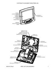
Motherboard Removal and Installation
Motherboard Removal and Installation
Motherboard Removal and Installation

Create successful ePaper yourself
Turn your PDF publications into a flip-book with our unique Google optimized e-Paper software.
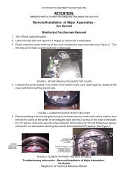
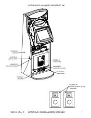
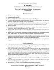
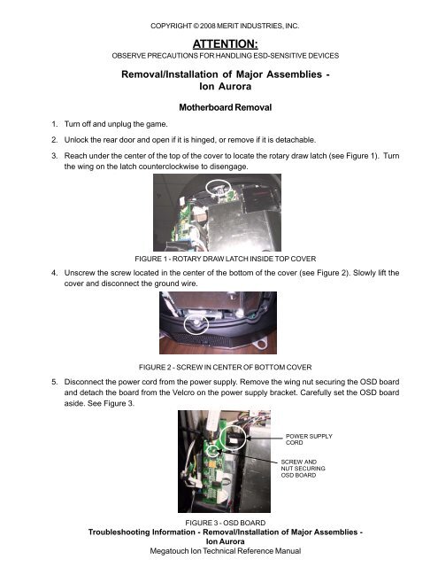
1. Turn off <strong>and</strong> unplug the game.COPYRIGHT © 2008 MERIT INDUSTRIES, INC.ATTENTION:OBSERVE PRECAUTIONS FOR HANDLING ESD-SENSITIVE DEVICES<strong>Removal</strong>/<strong>Installation</strong> of Major Assemblies -Ion Aurora<strong>Motherboard</strong> <strong>Removal</strong>2. Unlock the rear door <strong>and</strong> open if it is hinged, or remove if it is detachable.3. Reach under the center of the top of the cover to locate the rotary draw latch (see Figure 1). Turnthe wing on the latch counterclockwise to disengage.FIGURE 1 - ROTARY DRAW LATCH INSIDE TOP COVER4. Unscrew the screw located in the center of the bottom of the cover (see Figure 2). Slowly lift thecover <strong>and</strong> disconnect the ground wire.FIGURE 2 - SCREW IN CENTER OF BOTTOM COVER5. Disconnect the power cord from the power supply. Remove the wing nut securing the OSD board<strong>and</strong> detach the board from the Velcro on the power supply bracket. Carefully set the OSD boardaside. See Figure 3.POWER SUPPLYCORDSCREW ANDNUT SECURINGOSD BOARDFIGURE 3 - OSD BOARDTroubleshooting Information - <strong>Removal</strong>/<strong>Installation</strong> of Major Assemblies -Ion AuroraMegatouch Ion Technical Reference Manual
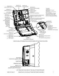
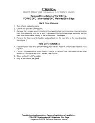
COPYRIGHT © 2008 MERIT INDUSTRIES, INC.ATTENTION:OBSERVE PRECAUTIONS FOR HANDLING ESD-SENSITIVE DEVICES<strong>Removal</strong>/<strong>Installation</strong> of Major Assemblies -Ion Aurora (cont’d)6. Remove the electronics tray by unscrewing the thumbscrew located in the middle of the rear of thetray <strong>and</strong> sliding the tray out. See Figure 4.THUMBSCREWSECURINGELECTRONICS TRAYFIGURE 4 - REAR VIEW OF ELECTRONICS TRAY7. If applicable, disconnect the three black connectors (10-, 11- <strong>and</strong> 12-pin) connecting the electronicstray to the game in order to slide the tray out further (see Figure 5). If your game does not havethese connectors, the harness is long enough to remove the tray.CONNECTORS CONNECTINGELECTRONICS TRAY TOGAME (3 PLACES)FIGURE 5 - REAR VIEW OF GAME8. Move the hard drive/power supply tower out of the way of the motherboard by tilting it on its hinge90 degrees to the left <strong>and</strong> supporting (if necessary). Remove all motherboard connections, notingtheir positions, <strong>and</strong> unscrew the motherboard in 6 places on a st<strong>and</strong>ard Aurora (see Figure 6), orin 2 places on an Aurora Widescreen (see Figure 7). Remove the motherboard from the tray.Troubleshooting Information - <strong>Removal</strong>/<strong>Installation</strong> of Major Assemblies -Ion AuroraMegatouch Ion Technical Reference Manual
COPYRIGHT © 2008 MERIT INDUSTRIES, INC.ATTENTION:OBSERVE PRECAUTIONS FOR HANDLING ESD-SENSITIVE DEVICES<strong>Removal</strong>/<strong>Installation</strong> of Major Assemblies -Ion Aurora (cont’d)SCREWSSECURINGMOTHERBOARD(6 PLACES)FIGURE 6 - SCREWS SECURING MOTHERBOARD TO GAMEIN STANDARD AURORASCREWSSECURINGMOTHERBOARD(2 PLACES)FIGURE 7 - SCREWS SECURING MOTHERBOARD TO GAMEIN AURORA WIDESCREENTroubleshooting Information - <strong>Removal</strong>/<strong>Installation</strong> of Major Assemblies -Ion AuroraMegatouch Ion Technical Reference Manual
COPYRIGHT © 2008 MERIT INDUSTRIES, INC.ATTENTION:OBSERVE PRECAUTIONS FOR HANDLING ESD-SENSITIVE DEVICES<strong>Removal</strong>/<strong>Installation</strong> of Major Assemblies -Ion Aurora (cont’d)<strong>Motherboard</strong> <strong>Installation</strong>1. Situate the new motherboard on top of the fish paper, <strong>and</strong> secure to the electronics tray with 6screws in a st<strong>and</strong>ard Aurora (see Figure 6) or 2 screws in an Aurora Widescreen (see Figure 7).2. Restore all motherboard connections. Restore the hard drive/power supply tower to its uprightposition, <strong>and</strong> slide the electronics tray back into place, making sure that the connectors on theback of the hard drive bracket click into the connectors on the wall of the game, if applicable (seeFigure 7). If you disconnected three connectors from the electronics tray to the game (see Figure5), reconnect them. Secure the tray by screwing in the thumbscrew. See Figure 4.CONNECTORSON GAME(3 PLACES) CONNECTORSON BACK OFHARD DRIVE(3 PLACES)NOTE: ELECTRONICS TRAYTURNED AROUND FORVIEWING PURPOSES.FIGURE 8 - CONNECTORS ON BACK OF HARD DRIVE BRACKET AND WALL OF GAMETroubleshooting Information - <strong>Removal</strong>/<strong>Installation</strong> of Major Assemblies -Ion AuroraMegatouch Ion Technical Reference Manual
COPYRIGHT © 2008 MERIT INDUSTRIES, INC.ATTENTION:OBSERVE PRECAUTIONS FOR HANDLING ESD-SENSITIVE DEVICES<strong>Removal</strong>/<strong>Installation</strong> of Major Assemblies -Ion Aurora (cont’d)3. Reconnect the power cord to the power supply. Reattach the OSD board to the Velcro on thepower supply bracket <strong>and</strong> secure with one wing nut. See Figure 3.4. Reconnect the ground wire to the rear cover <strong>and</strong> lower the cover into place, carefully lining up the2 tabs on the cover with the 2 mating holes on the sides of the game. See Figure 9. Make sure theplastic lip on the bottom of the rear cover is behind the metal base.TABMATING HOLENOTE: ONLY LEFT SIDE SHOWN.TAB AND MATING HOLE AREALSO ON RIGHT SIDE.Tighten the screw securing the bottom of the door. See Figure 2. Turn the wing on the draw latchclockwise to engage the latch (Figure 1).5. Close (or reattach) <strong>and</strong> lock the rear door.6. Plug in <strong>and</strong> turn on the game.FIGURE 9 - SIDE VIEW OF GAMETroubleshooting Information - <strong>Removal</strong>/<strong>Installation</strong> of Major Assemblies -Ion AuroraMegatouch Ion Technical Reference Manual