ELCT 501: Digital System Design
ELCT 501: Digital System Design
ELCT 501: Digital System Design
- No tags were found...

You also want an ePaper? Increase the reach of your titles
YUMPU automatically turns print PDFs into web optimized ePapers that Google loves.
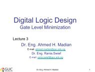
<strong>ELCT</strong> <strong>501</strong>:<strong>Digital</strong> <strong>System</strong> <strong>Design</strong>Lecture 7: <strong>System</strong> <strong>Design</strong>Dr. Mohamed Abd El Ghany,Department of Electronics and Electrical Engineering
Algorithmic State Machine (ASM)• For large machines, the designers often usea different form of representation, called thealgorithmic state machine chart.• An ASM chart is a type of flowchart that canbe used to represent the state transitionsand generated outputs for an FSM.Dr. Mohamed Abd el GhanyDepartment of Electronics and Electrical Engineering<strong>ELCT</strong> <strong>501</strong>: <strong>Digital</strong> <strong>System</strong><strong>Design</strong>Winter 20112
Elements used in ASM ChartsState nameState boxOutputsignals oractions(Moore type)0 (false) 1 (true)ConditionexpressionDecision boxConditional outputs oractions (Mealy type)Conditional output boxDr. Mohamed Abd el GhanyDepartment of Electronics and Electrical Engineering<strong>ELCT</strong> <strong>501</strong>: <strong>Digital</strong> <strong>System</strong><strong>Design</strong>Winter 20113
From FSM to ASM chartResetA0wB10Cw1Z0 1wDr. Mohamed Abd el GhanyDepartment of Electronics and Electrical Engineering<strong>ELCT</strong> <strong>501</strong>: <strong>Digital</strong> <strong>System</strong><strong>Design</strong>Winter 20114
From FSM to ASM chartResetA0Bw1z0 1wDr. Mohamed Abd el GhanyDepartment of Electronics and Electrical Engineering<strong>ELCT</strong> <strong>501</strong>: <strong>Digital</strong> <strong>System</strong><strong>Design</strong>Winter 20115
<strong>Design</strong> Example• <strong>Design</strong> A Bit-Counting Circuit to count thenumber of bits in a registerPseudocodeforthe bitcounterB = 0;While A ≠ 0 doif a0 = 1 thenB= B+1;end if;Right-shift A;End while;Dr. Mohamed Abd el GhanyDepartment of Electronics and Electrical Engineering<strong>ELCT</strong> <strong>501</strong>: <strong>Digital</strong> <strong>System</strong><strong>Design</strong>Winter 20116
ASM chart for thepseudo-codeResetS1B = 0;While A ≠ 0 doif a0 = 1 thenB= B+1;end if;Right-shift A;End while;Load AB
Datapath for the ASM chartData0nlog 2 n0LAEAwLEShift registerLBEBLECounterClockAlog 2 nnza0BDr. Mohamed Abd el GhanyDepartment of Electronics and Electrical Engineering<strong>ELCT</strong> <strong>501</strong>: <strong>Digital</strong> <strong>System</strong><strong>Design</strong>Winter 20118
ASM chart for thecontrol circuitResetS10S2LBs1EA0sS3Done1EBz100a01Dr. Mohamed Abd el GhanyDepartment of Electronics and Electrical Engineering<strong>ELCT</strong> <strong>501</strong>: <strong>Digital</strong> <strong>System</strong><strong>Design</strong>Winter 20119
VHDL for the bitcountingcircuitPart 1Dr. Mohamed Abd el GhanyDepartment of Electronics and Electrical Engineering<strong>ELCT</strong> <strong>501</strong>: <strong>Digital</strong> <strong>System</strong><strong>Design</strong>Winter 201110
VHDL for the bitcountingcircuitPart 2Dr. Mohamed Abd el GhanyDepartment of Electronics and Electrical Engineering<strong>ELCT</strong> <strong>501</strong>: <strong>Digital</strong> <strong>System</strong><strong>Design</strong>Winter 201111
VHDL for the bitcountingcircuitPart 3Dr. Mohamed Abd el GhanyDepartment of Electronics and Electrical Engineering<strong>ELCT</strong> <strong>501</strong>: <strong>Digital</strong> <strong>System</strong><strong>Design</strong>Winter 201112
VHDL for the bitcountingcircuitPart 4Dr. Mohamed Abd el GhanyDepartment of Electronics and Electrical Engineering<strong>ELCT</strong> <strong>501</strong>: <strong>Digital</strong> <strong>System</strong><strong>Design</strong>Winter 201113
ASM chart for themultiplierResetBinary1101x 1011--------------1101110100001101---------------10001111Load ALoad BP
Datapath circuit for the multiplier0 Data An nData BnClockLAEALEShift- leftregisterLBEBLEShift-rightregisterA2n+0Bnsum 2n 2nP selEP1 0DataP 2nEregisterzb02nDr. Mohamed Abd el GhanyDepartment of Electronics and Electrical EngineeringP<strong>ELCT</strong> <strong>501</strong>: <strong>Digital</strong> <strong>System</strong><strong>Design</strong>Winter 201117
ASM chart for themultiplier control circuitResetS1P sel =0, EPEP0s1S2P sel =1,EA, EBz10sS3Done10b001Dr. Mohamed Abd el GhanyDepartment of Electronics and Electrical Engineering<strong>ELCT</strong> <strong>501</strong>: <strong>Digital</strong> <strong>System</strong><strong>Design</strong>Winter 201118
VHDL for themultiplier circuitPart 1Dr. Mohamed Abd el GhanyDepartment of Electronics and Electrical Engineering<strong>ELCT</strong> <strong>501</strong>: <strong>Digital</strong> <strong>System</strong><strong>Design</strong>Winter 201119
VHDL for themultiplier circuitPart 2Dr. Mohamed Abd el GhanyDepartment of Electronics and Electrical Engineering<strong>ELCT</strong> <strong>501</strong>: <strong>Digital</strong> <strong>System</strong><strong>Design</strong>Winter 201120
VHDL for themultiplier circuitPart 3Dr. Mohamed Abd el GhanyDepartment of Electronics and Electrical Engineering<strong>ELCT</strong> <strong>501</strong>: <strong>Digital</strong> <strong>System</strong><strong>Design</strong>Winter 201121
VHDL for themultiplier circuitPart 4Dr. Mohamed Abd el GhanyDepartment of Electronics and Electrical Engineering<strong>ELCT</strong> <strong>501</strong>: <strong>Digital</strong> <strong>System</strong><strong>Design</strong>Winter 201122
Clock Synchronization• Clock Skew:If the circuit of clock enable is used,then the flip-flops without the enableinput will observe changes in theclock signal slightly earlier than theflip-flops that have the enable input.This situation , in which the clocksignal arrives at different times atdifferent flip-flops, is known as clockskew.Similar problems arise in a chip inwhich the clock signal is distributedto different flip-flops by wires whoselengths vary appreciably.clockEData D QQ’ClockenablecircuitDr. Mohamed Abd el GhanyDepartment of Electronics and Electrical Engineering<strong>ELCT</strong> <strong>501</strong>: <strong>Digital</strong> <strong>System</strong><strong>Design</strong>Winter 201123
Clock Synchronization• Clock Skew:For proper operation ofsynchronous sequentialcircuits, it is essential tominimize the clock skew asmuch as possible.The clock signal isdistributed to the flip-flopssuch that the length of wirebetween each flip-flop andclock source is the same.An H tree clockdistribution networkDr. Mohamed Abd el GhanyDepartment of Electronics and Electrical Engineering<strong>ELCT</strong> <strong>501</strong>: <strong>Digital</strong> <strong>System</strong><strong>Design</strong>Winter 201124