Active RC filters Design Techniques - GUC - Faculty of Information ...
Active RC filters Design Techniques - GUC - Faculty of Information ...
Active RC filters Design Techniques - GUC - Faculty of Information ...

Create successful ePaper yourself
Turn your PDF publications into a flip-book with our unique Google optimized e-Paper software.
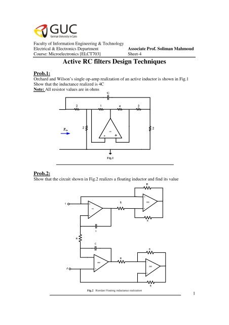
<strong>Faculty</strong> <strong>of</strong> <strong>Information</strong> Engineering & TechnologyElectrical & Electronics DepartmentCourse: Microelectronics [ELCT703]Associate Pr<strong>of</strong>. Soliman MahmoudSheet-4<strong>Active</strong> <strong>RC</strong> <strong>filters</strong> <strong>Design</strong> <strong>Techniques</strong>Prob.1:Orchard and Wilson’s single op-amp realization <strong>of</strong> an active inductor is shown in Fig.1Show that the inductance realized is 4CNote: All resistor values are in ohms∞Prob.2:Show that the circuit shown in Fig.2 realizes a floating inductor and find its value∞∞∞∞1
Prob.3:In this problem several realizations <strong>of</strong> third order Butterworth LPF having the followingtransfer function are consideredi. For the passive LPF shown in fig.3a, find to realize the transferfunction given by equation 1, Evaluate K.ii. Find the active <strong>RC</strong> LPF by using the synthetic inductance approach.iii. Apply Bruton’s transformation to the filter <strong>of</strong> fig.1, hence find the active <strong>RC</strong>realization (using the GIC to realize the FDNR)iv. Fig. 3b represents the active K<strong>RC</strong> realization <strong>of</strong> eqn.1 using the cascadeapproach. Takefind the values <strong>of</strong>v. Fig.3c represents a single op-amp realization <strong>of</strong> a third order LPF. Takefind the design values <strong>of</strong>1ΩLC1C21Ω( K −1)rr-+C 1 -R 3∞R 1 R 2C 2+C 3+∞+V outV in- -Fig.3b2
+-R 1 R 2 R 3C 1 C 3C 2K+V out-V in+Fig.3cProb.4:Synthesize the following real pole transfer functions using active <strong>RC</strong> circuits with no morethan one op-amp:a. b. c.d. e. f.Prob.5:A first order all-pass section characterized byfig.4. Develop the design equations.can be realized using the circuit inKRV in<strong>RC</strong>-∞V outR 1R 1Fig.43
Prob.6:Fig.5 represents two more first order all-pass networks:a. Find K to make all-pass.b. Sketch the phase versus for each <strong>of</strong> the two circuits.c. <strong>Design</strong> a circuit to provide a phase shift <strong>of</strong> at a radian frequency. (Take C=0.1µF)KR 1V inR 1C-+∞V outRFig.5aKR 1V inR 1R-+∞V outCFig.5b4
Prob.7:Realize the given transfer function T(s) using the Sallen-Key lowpass circuit in Fig.6using the equal R, equal C design and find H.Show that the circuit can be adopted to change toProb.8:Consider the Sallen-Key lowpass circuit in Fig.6 with the following choice made for thedesign <strong>of</strong> elements:<strong>Design</strong> 3 (Saraga <strong>Design</strong>):a. Find the design equationsb. Compute the sensitivities <strong>of</strong> and Q to all the circuit elements and comparewith the sensitivities in designs 1 and 2c. <strong>Design</strong> a LPF having ; Q=10 (Take )Prob.9:Repeat problem 4 for the following alternative design; <strong>Design</strong> 4:Note: in part (c) take5
Prob.10:<strong>Design</strong> a Sallen-Key filter for realizing the given T(s) using two op-amps, 4R and 4C onlyand find H. (obtain as large H as possible)Prob.11: Find the Leap Frog equivalent active network for the following circuit using6