SITC OF LT Switch gear for Doordarshan, HPT Vizag - All India Radio
SITC OF LT Switch gear for Doordarshan, HPT Vizag - All India Radio
SITC OF LT Switch gear for Doordarshan, HPT Vizag - All India Radio
Create successful ePaper yourself
Turn your PDF publications into a flip-book with our unique Google optimized e-Paper software.
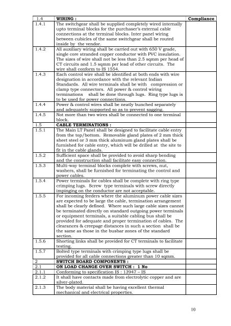
1.4 WIRING : Compliance1.4.1 The switch<strong>gear</strong> shall be supplied completely wired internallyupto terminal blocks <strong>for</strong> the purchaser’s external cableconnections at the terminal blocks. Inter panel wiringbetween cubicles of the same switch<strong>gear</strong> shall be routedinside by the vendor.1.4.2 <strong>All</strong> auxiliary wiring shall be carried out with 650 V grade,single core stranded copper conductor with PVC insulation.The sizes of wire shall not be less than 2.5 sqmm per head ofCT circuits and 1.5 sqmm per lead of other circuits. Thewire shall con<strong>for</strong>m to IS 1554.1.4.3 Each control wire shall be identified at both ends with wiredesignation in accordance with the relevant <strong>India</strong>nStandards. <strong>All</strong> wire terminals shall be with compression orclamp type connectors. <strong>All</strong> power & control wiringterminations shall be done through lugs. Ring type lugs isto be used <strong>for</strong> power connections.1.4.4 Power & control wires shall be neatly bunched separatelyand adequately supported so as to prevent sagging.1.4.5 Not more than two wires shall be connected to one terminalblock.1.5 CABLE TERMINATIONS :1.5.1 The Main <strong>LT</strong> Panel shall be designed to facilitate cable entryfrom the top/bottom. Removable gland plates of 2 mm thicksheet steel or 3 mm thick aluminum gland plates shall befurnished <strong>for</strong> cable entry, which will be drilled at the site tofit in the cable glands.1.5.2 Sufficient space shall be provided to avoid sharp bendingand the construction shall facilitate easy connection.1.5.3 Multi-way terminal blocks complete with screws, nut,washers, shall be furnished <strong>for</strong> terminating the control andpower cables.1.5.4 Power terminals <strong>for</strong> cables shall be complete with ring typecrimping lugs. Screw type terminals with screw directlyimpinging on the conductor are not acceptable.1.5.5 For incoming feeders where the aluminum power cable sizesare expected to be large the cable, termination arrangementshall be clearly defined. Where such large cable sizes cannotbe terminated directly on standard outgoing power terminalsor equipment terminals, a suitable cabling bus shall beprovided <strong>for</strong> adequate and proper termination of cables. Theclearances & creepage distances in such a section shall bethe same as those in the busbar zones of the standardsection.1.5.6 Shorting links shall be provided <strong>for</strong> CT terminals to facilitatetesting.1.5.7 Bolted type terminals with crimping type lugs shall beprovided <strong>for</strong> all cable connections greater than 10 sqmm.2 SWITCH BOARD COMPONENTS :2.1 ON LOAD CHANGE OVER SWITCH : 1 No2.1.1 Con<strong>for</strong>ming to specification IS : 13947 – IS2.1.2 It shall have contacts made from electrolytic copper and aresilver-plated.2.1.3 The body material shall be having excellent thermalmechanical and electrical properties.10


