

Diesel Distributor Fuel-Injection Pumps VE - Gnarlodious
Diesel Distributor Fuel-Injection Pumps VE - Gnarlodious
Diesel Distributor Fuel-Injection Pumps VE - Gnarlodious
- No tags were found...

You also want an ePaper? Increase the reach of your titles
YUMPU automatically turns print PDFs into web optimized ePapers that Google loves.
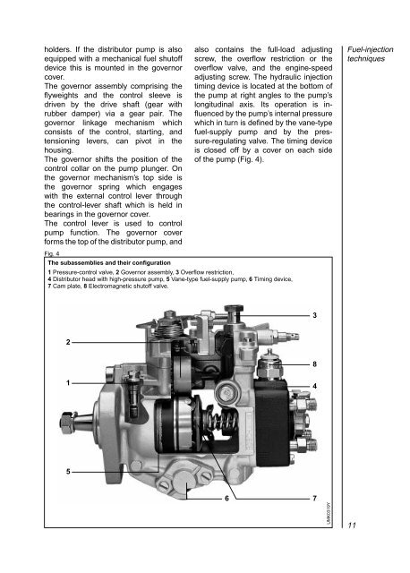
holders. If the distributor pump is alsoequipped with a mechanical fuel shutoffdevice this is mounted in the governorcover.The governor assembly comprising theflyweights and the control sleeve isdriven by the drive shaft (gear withrubber damper) via a gear pair. Thegovernor linkage mechanism whichconsists of the control, starting, andtensioning levers, can pivot in thehousing.The governor shifts the position of thecontrol collar on the pump plunger. Onthe governor mechanism’s top side isthe governor spring which engageswith the external control lever throughthe control-lever shaft which is held inbearings in the governor cover.The control lever is used to controlpump function. The governor coverforms the top of the distributor pump, andalso contains the full-load adjustingscrew, the overflow restriction or theoverflow valve, and the engine-speedadjusting screw. The hydraulic injectiontiming device is located at the bottom ofthe pump at right angles to the pump’slongitudinal axis. Its operation is influencedby the pump’s internal pressurewhich in turn is defined by the vane-typefuel-supply pump and by the pressure-regulatingvalve. The timing deviceis closed off by a cover on each sideof the pump (Fig. 4).<strong>Fuel</strong>-injectiontechniquesFig. 4The subassemblies and their configuration1 Pressure-control valve, 2 Governor assembly, 3 Overflow restriction,4 <strong>Distributor</strong> head with high-pressure pump, 5 Vane-type fuel-supply pump, 6 Timing device,7 Cam plate, 8 Electromagnetic shutoff valve.3281456 7UMK0319Y11
