

Diesel Distributor Fuel-Injection Pumps VE - Gnarlodious
Diesel Distributor Fuel-Injection Pumps VE - Gnarlodious
Diesel Distributor Fuel-Injection Pumps VE - Gnarlodious
- No tags were found...

You also want an ePaper? Increase the reach of your titles
YUMPU automatically turns print PDFs into web optimized ePapers that Google loves.
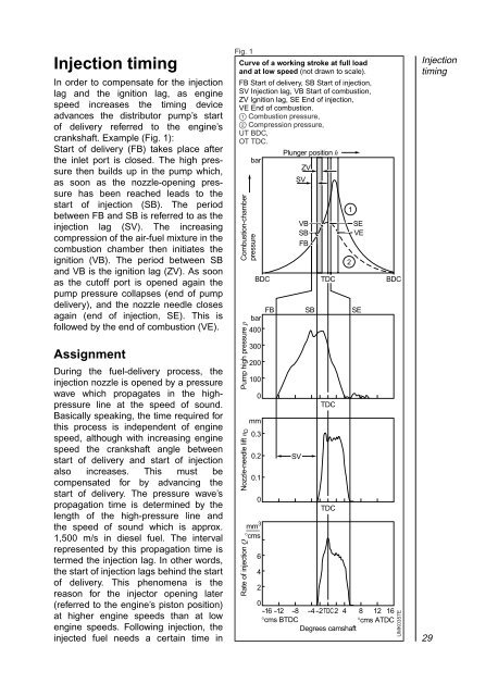
<strong>Injection</strong> timingIn order to compensate for the injectionlag and the ignition lag, as enginespeed increases the timing deviceadvances the distributor pump’s startof delivery referred to the engine’scrankshaft. Example (Fig. 1):Start of delivery (FB) takes place afterthe inlet port is closed. The high pressurethen builds up in the pump which,as soon as the nozzle-opening pressurehas been reached leads to thestart of injection (SB). The periodbetween FB and SB is referred to as theinjection lag (SV). The increasingcompression of the air-fuel mixture in thecombustion chamber then initiates theignition (VB). The period between SBand VB is the ignition lag (ZV). As soonas the cutoff port is opened again thepump pressure collapses (end of pumpdelivery), and the nozzle needle closesagain (end of injection, SE). This isfollowed by the end of combustion (<strong>VE</strong>).AssignmentDuring the fuel-delivery process, theinjection nozzle is opened by a pressurewave which propagates in the highpressureline at the speed of sound.Basically speaking, the time required forthis process is independent of enginespeed, although with increasing enginespeed the crankshaft angle betweenstart of delivery and start of injectionalso increases. This must becompensated for by advancing thestart of delivery. The pressure wave’spropagation time is determined by thelength of the high-pressure line andthe speed of sound which is approx.1,500 m/s in diesel fuel. The intervalrepresented by this propagation time istermed the injection lag. In other words,the start of injection lags behind the startof delivery. This phenomena is thereason for the injector opening later(referred to the engine’s piston position)at higher engine speeds than at lowengine speeds. Following injection, theinjected fuel needs a certain time inFig. 1Curve of a working stroke at full loadand at low speed (not drawn to scale).FB Start of delivery, SB Start of injection,SV <strong>Injection</strong> lag, VB Start of combustion,ZV Ignition lag, SE End of injection,<strong>VE</strong> End of combustion.1 Combustion pressure,2 Compression pressure,UT BDC,OT TDC.Plunger position hbarZVSVCombustion-chamberpressurePump high pressure pNozzle-needle lift n DRate of injection QBDC TDC BDCbar4003002001000mm0.30.20.10mm 3°cms642SVVBSBFBTDCTDCSE<strong>VE</strong>FB SB SE0-16 -12 -8 -4-2 TDC2 4 8 12 16°cms BTDC°cms ATDCDegrees camshaft12UMK0357E<strong>Injection</strong>timing29
