

Diesel Distributor Fuel-Injection Pumps VE - Gnarlodious
Diesel Distributor Fuel-Injection Pumps VE - Gnarlodious
Diesel Distributor Fuel-Injection Pumps VE - Gnarlodious
- No tags were found...

Create successful ePaper yourself
Turn your PDF publications into a flip-book with our unique Google optimized e-Paper software.
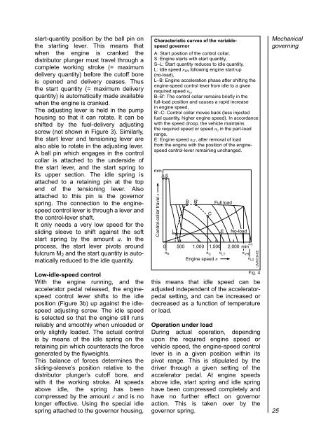
start-quantity position by the ball pin onthe starting lever. This means thatwhen the engine is cranked thedistributor plunger must travel through acomplete working stroke (= maximumdelivery quantity) before the cutoff boreis opened and delivery ceases. Thusthe start quantity (= maximum deliveryquantity) is automatically made availablewhen the engine is cranked.The adjusting lever is held in the pumphousing so that it can rotate. It can beshifted by the fuel-delivery adjustingscrew (not shown in Figure 3). Similarly,the start lever and tensioning lever arealso able to rotate in the adjusting lever.A ball pin which engages in the controlcollar is attached to the underside ofthe start lever, and the start spring toits upper section. The idle spring isattached to a retaining pin at the topend of the tensioning lever. Alsoattached to this pin is the governorspring. The connection to the enginespeedcontrol lever is through a lever andthe control-lever shaft.It only needs a very low speed for thesliding sleeve to shift against the softstart spring by the amount a. In theprocess, the start lever pivots aroundfulcrum M 2 and the start quantity is automaticallyreduced to the idle quantity.Low-idle-speed controlWith the engine running, and theaccelerator pedal released, the enginespeedcontrol lever shifts to the idleposition (Figure 3b) up against the idlespeedadjusting screw. The idle speedis selected so that the engine still runsreliably and smoothly when unloaded oronly slightly loaded. The actual controlis by means of the idle spring on theretaining pin which counteracts the forcegenerated by the flyweights.This balance of forces determines thesliding-sleeve’s position relative to thedistributor plunger’s cutoff bore, andwith it the working stroke. At speedsabove idle, the spring has beencompressed by the amount c and is nolonger effective. Using the special idlespring attached to the governor housing,Characteristic curves of the variablespeedgovernorA: Start position of the control collar,S: Engine starts with start quantity,S–L: Start quantity reduces to idle quantity,L: Idle speed n LN following engine start-up(no-load),L–B: Engine acceleration phase after shifting theengine-speed control lever from idle to a givenrequired speed n c ,B–B': The control collar remains briefly in thefull-load position and causes a rapid increasein engine speed,B'–C: Control collar moves back (less injectedfuel quantity, higher engine speed). In accordancewith the speed droop, the vehicle maintainsthe required speed or speed n c in the part-loadrange,E: Engine speed n LT , after removal of loadfrom the engine with the position of the enginespeedcontrol-lever remaining unchanged.mmA SControl-collar travel sB B' Full loadL E No-load0 500 1,000 1,500 2,000 min –1n A n C n LT n VHnLOEngine speed nthis means that idle speed can beadjusted independent of the acceleratorpedalsetting, and can be increased ordecreased as a function of temperatureor load.Operation under loadDuring actual operation, dependingupon the required engine speed orvehicle speed, the engine-speed controllever is in a given position within itspivot range. This is stipulated by thedriver through a given setting of theaccelerator pedal. At engine speedsabove idle, start spring and idle springhave been compressed completely andhave no further effect on governoraction. This is taken over by thegovernor spring.CUMK0348EFig. 4Mechanicalgoverning25
