

Diesel Distributor Fuel-Injection Pumps VE - Gnarlodious
Diesel Distributor Fuel-Injection Pumps VE - Gnarlodious
Diesel Distributor Fuel-Injection Pumps VE - Gnarlodious
- No tags were found...

Create successful ePaper yourself
Turn your PDF publications into a flip-book with our unique Google optimized e-Paper software.
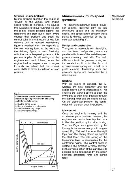
Overrun (engine braking)During downhill operation the engine is“driven” by the vehicle, and enginespeed tends to increase. This causesthe flyweights to move outwards so thatthe sliding sleeve presses against thetensioning and start levers. Both leverschange their position and push thecontrol collar in the direction of less fueldelivery until a reduced fuel-deliveryfigure is reached which corresponds tothe new loading level. At the extreme,the delivery figure is zero. Basically,with the variable-speed governor, thisprocess applies for all settings of theengine-speed control lever, when theengine load or engine speed changesto such an extent that the controlcollar shifts to either its full-load or stopposition.Fig. 6Characteristic curves of the minimummaximum-speedgovernor with idle springand intermediate springa Starting-spring range,b Range of starting and idle spring,d Intermediate-spring range,f Governor-spring range.mmControl-collar travel sa b d Uncontrolled fFull loadNo-loadMinimum-maximum-speedgovernorThe minimum-maximum-speed governorcontrols (governs) only the idle(minimum) speed and the maximumspeed. The speed range between thesepoints is directly controlled by the acceleratorpedal (Fig. 6).Design and constructionThe governor assembly with flyweights,and the lever configuration, are comparablewith those of the variable-speedgovernor already dealt with. The maindifference lies in the governor spring andits installation. It is in the form ofa compression spring and is held in aguide element. Tensioning lever andgovernor spring are connected by aretaining pin.StartingWith the engine at standstill, the flyweightsare also stationary and thesliding sleeve is in its initial position. Thisenables the starting spring to push theflyweights to their inner position throughthe starting lever and the sliding sleeve.On the distributor plunger, the controlcollar is in the start-quantity position.Idle controlOnce the engine is running and theaccelerator pedal has been released, theengine-speed control lever is pulled backto the idle position by its return spring.The centrifugal force generated by theflyweights increases along with enginespeed (Fig. 7a) and the inner flyweightlegs push the sliding sleeve up againstthe start lever. The idle spring on thetensioning lever is responsible for thecontrolling action. The control collar isshifted in the direction of “less delivery”by the pivoting action of the start lever, itsposition being determined by interactionbetween centrifugal force and springforce.MechanicalgoverningEngine speed n min –1UMK0351E27
