

Diesel Distributor Fuel-Injection Pumps VE - Gnarlodious
Diesel Distributor Fuel-Injection Pumps VE - Gnarlodious
Diesel Distributor Fuel-Injection Pumps VE - Gnarlodious
- No tags were found...

Create successful ePaper yourself
Turn your PDF publications into a flip-book with our unique Google optimized e-Paper software.
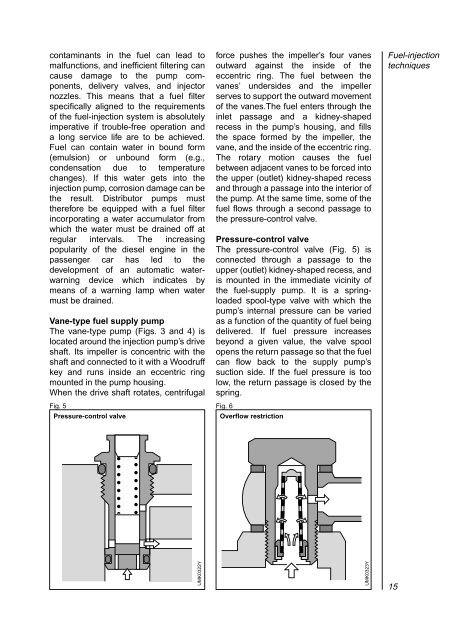
contaminants in the fuel can lead tomalfunctions, and inefficient filtering cancause damage to the pump components,delivery valves, and injectornozzles. This means that a fuel filterspecifically aligned to the requirementsof the fuel-injection system is absolutelyimperative if trouble-free operation anda long service life are to be achieved.<strong>Fuel</strong> can contain water in bound form(emulsion) or unbound form (e.g.,condensation due to temperaturechanges). If this water gets into theinjection pump, corrosion damage can bethe result. <strong>Distributor</strong> pumps musttherefore be equipped with a fuel filterincorporating a water accumulator fromwhich the water must be drained off atregular intervals. The increasingpopularity of the diesel engine in thepassenger car has led to thedevelopment of an automatic waterwarningdevice which indicates bymeans of a warning lamp when watermust be drained.Vane-type fuel supply pumpThe vane-type pump (Figs. 3 and 4) islocated around the injection pump’s driveshaft. Its impeller is concentric with theshaft and connected to it with a Woodruffkey and runs inside an eccentric ringmounted in the pump housing.When the drive shaft rotates, centrifugalFig. 5Pressure-control valveforce pushes the impeller’s four vanesoutward against the inside of theeccentric ring. The fuel between thevanes’ undersides and the impellerserves to support the outward movementof the vanes.The fuel enters through theinlet passage and a kidney-shapedrecess in the pump’s housing, and fillsthe space formed by the impeller, thevane, and the inside of the eccentric ring.The rotary motion causes the fuelbetween adjacent vanes to be forced intothe upper (outlet) kidney-shaped recessand through a passage into the interior ofthe pump. At the same time, some of thefuel flows through a second passage tothe pressure-control valve.Pressure-control valveThe pressure-control valve (Fig. 5) isconnected through a passage to theupper (outlet) kidney-shaped recess, andis mounted in the immediate vicinity ofthe fuel-supply pump. It is a springloadedspool-type valve with which thepump’s internal pressure can be variedas a function of the quantity of fuel beingdelivered. If fuel pressure increasesbeyond a given value, the valve spoolopens the return passage so that the fuelcan flow back to the supply pump’ssuction side. If the fuel pressure is toolow, the return passage is closed by thespring.Fig. 6Overflow restriction<strong>Fuel</strong>-injectiontechniquesUMK0322YUMK0323Y15
