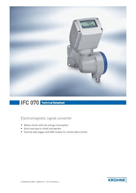
IFC 070 Technical Datasheet
IFC 070 Technical Datasheet
IFC 070 Technical Datasheet
- No tags were found...

You also want an ePaper? Increase the reach of your titles
YUMPU automatically turns print PDFs into web optimized ePapers that Google loves.
CONTENTS<strong>IFC</strong> <strong>070</strong>1 Product features 31.1 Solution for the water and wastewater industry ............................................................. 31.2 Features............................................................................................................................ 51.3 Measuring principle.......................................................................................................... 72 <strong>Technical</strong> data 82.1 <strong>Technical</strong> data................................................................................................................... 82.2 Measuring accuracy ....................................................................................................... 112.3 Dimensions and weights ................................................................................................ 123 Installation 133.1 Notes on installation ......................................................................................................133.2 Mounting position and flange deviation ......................................................................... 133.3 Vibration.......................................................................................................................... 143.4 Magnetic field ................................................................................................................. 144 Electrical connections 154.1 Safety instructions.......................................................................................................... 154.2 Installation of converter ................................................................................................. 154.3 Grounding ....................................................................................................................... 154.4 Connection of signal cable ............................................................................................. 164.5 Terminal assignment of converter................................................................................. 175 Notes 182 www.krohne.com 04/2009 - 4000572101 - TD <strong>IFC</strong> <strong>070</strong> R02 en
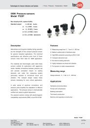
<strong>IFC</strong> <strong>070</strong>PRODUCT FEATURES 11.1 Solution for the water and wastewater industryThe <strong>IFC</strong> <strong>070</strong> electromagnetic signal converter is designed for use in water industry such aspotable water distribution networks, for revenue billing and for water abstraction. It is batterypowered, making it especially suitable for applications where no power connection is availableand provides certainty in case of power failure. Optional a GSM and data logger module isavailable for the remote transmission of measurement data and status information.1 Battery-powered totaliser2 Rigid flow sensor04/2009 - 4000572101 - TD <strong>IFC</strong> <strong>070</strong> R02 enwww.krohne.com3
<strong>IFC</strong> <strong>070</strong>PRODUCT FEATURES 11.2 FeaturesGSM and data logger moduleThere is an increased demand by utilities forremote reading. Often water meters areinstalled at remote locations in thedistribution network or below the ground forexample in busy city centers. The <strong>IFC</strong> <strong>070</strong> canbe supplied with a state-of-the-art data loggerand GSM modem. The stored data istranmitted (for example once a day) by SMSand can be forwarded to the customer'smanagement system.Quick to install and easy to operate - Remoteor CompactThe <strong>IFC</strong> <strong>070</strong> signal converter can be suppliedin either compact or remote design. In case ofa remote design, the converter can beinstalled on the wall or on a pipe. Thefunctionality of the compact and remoteversions is identical.04/2009 - 4000572101 - TD <strong>IFC</strong> <strong>070</strong> R02 enwww.krohne.com5
1 PRODUCT FEATURES<strong>IFC</strong> <strong>070</strong>Low energy consumptionThe <strong>IFC</strong> <strong>070</strong> signal converter has an extremelow power consumption. It delivers preciseand reliable measurements for many yearsoperating on batteries. With a sampling rate of1/15 Hz, the water meter can operate for morethan fifteen years.Long term reliabilityIn addition to a long battery lifetime of up to 15years, the <strong>IFC</strong> <strong>070</strong> provides diagnosticinformation. The <strong>IFC</strong> <strong>070</strong> has two statusoutputs for self checking, battery warningsand counter overrun.6www.krohne.com04/2009 - 4000572101 - TD <strong>IFC</strong> <strong>070</strong> R02 en
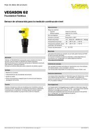
<strong>IFC</strong> <strong>070</strong>PRODUCT FEATURES 11.3 Measuring principleAn electrically conductive fluid flows inside an electrically insulating pipe through a magneticfield. This magnetic field is generated by a current, flowing through a pair of field coils. Inside ofthe fluid, a voltage U is generated:U = v * k * B * Din which:v = mean flow velocityk = factor correcting for geometryB = magnetic field strengthD = inner diameter of flow meterThe signal voltage U is picked off by electrodes and is proportional to the mean flow velocity vand thus the flow rate q. The signal voltage is quite small (typically 1 mV at v = 3 m/s / 10 ft/s andfield coil power of 1 W). Finally, a signal converter is used to amplify the signal voltage, filter it(separate from noise) and convert it into signals for totalising, recording and output processing.1 Voltage (induced voltage proportional to flow velocity)2 Electrodes3 Magnetic field4 Field coils04/2009 - 4000572101 - TD <strong>IFC</strong> <strong>070</strong> R02 enwww.krohne.com7
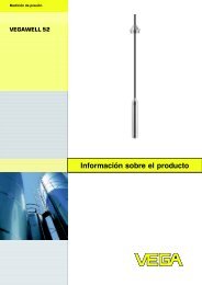
2 TECHNICAL DATA<strong>IFC</strong> <strong>070</strong>2.3 Dimensions and weightsCompact versiona = 170 mm / 6.7"b = 122 mm / 4.8"c = 140 mm / 5.5"Sizes of sensor can be found in the relevantdatasheet.Remote version, signal converterb = 122 mm / 4.8"c = 335 mm / 13.2"H = 310 mm / 12.2"12www.krohne.com04/2009 - 4000572101 - TD <strong>IFC</strong> <strong>070</strong> R02 en
<strong>IFC</strong> <strong>070</strong>INSTALLATION 33.1 Notes on installationInspect the cartons carefully for damage or signs of rough handling. Report damage to thecarrier and to the local office of the manufacturer.Check the packing list to check if you received completely all that you ordered.Look at the device nameplate to ensure that the device is delivered according to your order.Check for the correct supply voltage printed on the nameplate.3.2 Mounting position and flange deviationFigure 3-1: Mounting position and flange deviation1 L max2 L min• Mount flowmeter either with converter aligned upwards or downwards.• Install flowmeter in line with the pipe axis.• Pipe flange faces must be parallel to each other.Max. permissible deviation of pipe flange faces: L max - L min ≤ 0.5 mm04/2009 - 4000572101 - TD <strong>IFC</strong> <strong>070</strong> R02 enwww.krohne.com13
3 INSTALLATION<strong>IFC</strong> <strong>070</strong>3.3 VibrationFigure 3-2: Avoid vibrations3.4 Magnetic fieldFigure 3-3: Avoid magnetic fields14www.krohne.com04/2009 - 4000572101 - TD <strong>IFC</strong> <strong>070</strong> R02 en
<strong>IFC</strong> <strong>070</strong>ELECTRICAL CONNECTIONS 44.1 Safety instructions4.2 Installation of converter4.3 GroundingAll work on the electrical connections may only be carried out with the power disconnected. Takenote of the voltage data on the nameplate!Observe the national regulations for electrical installations!Observe without fail the local occupational health and safety regulations. Any work done on theelectrical components of the measuring device may only be carried out by properly trainedspecialists.Look at the device nameplate to ensure that the device is delivered according to your order.Check for the correct supply voltage printed on the nameplate.Only applicable for remote versions.• Mount converter with mounting plate on wall or standpipe.• Keep distance between sensor and signal converter as short as possible.• Observe length of the delivered signal cable.Figure 4-1: Grounding04/2009 - 4000572101 - TD <strong>IFC</strong> <strong>070</strong> R02 enwww.krohne.com15
4 ELECTRICAL CONNECTIONS<strong>IFC</strong> <strong>070</strong>4.4 Connection of signal cableThe signal cable is only used with remote versions. The standard cable includes both electrodeand field current leads, the optional type A / B cable is only used for the electrodes. In that case,the field current cable is no part of the supply.Figure 4-2: Cable connection at converter side, standard cable1 cable length: 13 cm / 5"2 cable length: 5 cm / 2"3 brown + white cable, used for field current4 purple and blue cable, used for electrode signals5 cable length: 8 cm / 3"6 Shield (terminal 1 of connector X2 + U-clamp• Prepare appropiate cable lengths (1...3)• Connect the shield to the U-clamp, the brown cable to terminal 7 and the white to terminal 8.• Connect the shield to terminal 1, the purple cable (red in case of type A or B cable) to terminal2 and the blue (white in case of type A or B cable) to terminal 3.16www.krohne.com04/2009 - 4000572101 - TD <strong>IFC</strong> <strong>070</strong> R02 en
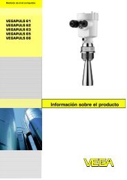
<strong>IFC</strong> <strong>070</strong>ELECTRICAL CONNECTIONS 44.5 Terminal assignment of converterFigure 4-3: Removing side capFigure 4-4: Terminal assignment1 Status output 12 Status output 23 Not connected4 Ground5 Pulse output A6 Pulse output BElectrical values• Pulse output passive:f ≤ 500 Hz; I ≤ 10 mA; U: 5...24 VDC (P ≤ 100 mW)• Status output passive:I ≤ 10 mA; U: 5...24 VDC (P ≤ 100 mW)04/2009 - 4000572101 - TD <strong>IFC</strong> <strong>070</strong> R02 enwww.krohne.com17
5 NOTES<strong>IFC</strong> <strong>070</strong>18www.krohne.com04/2009 - 4000572101 - TD <strong>IFC</strong> <strong>070</strong> R02 en
<strong>IFC</strong> <strong>070</strong>NOTES 504/2009 - 4000572101 - TD <strong>IFC</strong> <strong>070</strong> R02 enwww.krohne.com19
KKKKROHNE product overview© KROHNE 04/2009 - 4000572101 - TD <strong>IFC</strong> <strong>070</strong> R02 en - Subject to change without notice.• Electromagnetic flowmeters• Variable area flowmeters• Ultrasonic flowmeters• Mass flowmeters• Vortex flowmeters• Flow controllers• Level meters• Temperature meters• Pressure meters• Analysis products• Measuring systems for the oil and gas industry• Measuring systems for sea-going tankersHead Office KROHNE Messtechnik GmbH & Co. KGLudwig-Krohne-Str. 5D-47058 DuisburgTel.:+49 (0)203 301 0Fax:+49 (0)203 301 10389info@krohne.deThe current list of all KROHNE contacts and addresses can be found at:www.krohne.com