F-16 ARF Assembly Manual - E-flite
F-16 ARF Assembly Manual - E-flite
F-16 ARF Assembly Manual - E-flite
- No tags were found...

You also want an ePaper? Increase the reach of your titles
YUMPU automatically turns print PDFs into web optimized ePapers that Google loves.
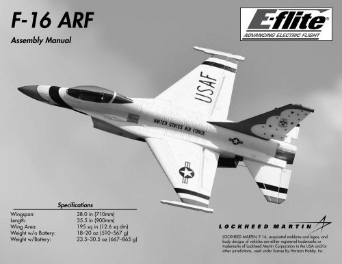
Table of ContentsIntroduction......................................................................................................................... 2Using the <strong>Manual</strong>................................................................................................................ 2Product Registration............................................................................................................. 3Contents of Kit/Parts Layout................................................................................................. 3Recommended Radio Equipment........................................................................................... 3Recommended Sport Ducted Fan Setup................................................................................. 3Recommended High Power Ducted Fan Setup........................................................................ 4Optional Accessories........................................................................................................... 4Required Tools and Adhesives.............................................................................................. 4Notes Regarding Servos and ESC......................................................................................... 4Note on Lithium Polymer Batteries......................................................................................... 4Warning............................................................................................................................. 4Ducted Fan Installation......................................................................................................... 5Wing and Stabilizer Installation............................................................................................ 7Elevator and Aileron Servo Installation.................................................................................. 9Landing Gear Installation Sport Ducted Fan Installation........................................................ 13Landing Gear Installation High-Power Ducted Fan Installation............................................... 17Speed Control and Receiver Installation Sport Ducted Fan Installation.................................... 21Speed Control and Receiver Installation High-Powered Ducted Fan Installation....................... 22Vertical and Ventral Fin Installation..................................................................................... 24Motor Battery Installation Sport Ducted Fan Installation........................................................ 25Motor Battery Installation High-Power Ducted Fan Installation............................................... 26Missile Installation (Optional).............................................................................................. 26Removing Fan and Motor for Servicing or Replacement....................................................... 27Radio Programming........................................................................................................... 28Control Throws.................................................................................................................. 28Center of Gravity............................................................................................................... 29Preflight............................................................................................................................ 29Range Test Your Radio........................................................................................................ 30Flying Your F-<strong>16</strong>................................................................................................................ 30Safety Do’s and Don’ts for Pilots......................................................................................... 30Age Requirements.............................................................................................................. 30Safety, Precautions and Warnings....................................................................................... 31Warranty Information........................................................................................................ 31Instructions for Disposal of WEEE by Users in the European Union........................................ 332008 Official Academy of Model Aeronautics Safety Code.................................................. 33Building and Flying Notes:................................................................................................. 35IntroductionThe F-<strong>16</strong> Fighting Falcon was originally designedin 1971 to be a multi-role fighter in both air-to-aircombat and air-to-surface attacks. Today the F-<strong>16</strong> isknown for its amazing maneuverability, precision strikeand attack capabilities and speed. The F-<strong>16</strong>’s versatilityallows it to be equipped with a variety of weapons,including missiles or bombs. The Fighting Falconis still in use today and is currently serving manycountries. The USAF uses F-<strong>16</strong>s in their Thunderbirddemonstrations.E-<strong>flite</strong>’s F-<strong>16</strong> 400 DF (ducted fan) is designed toreplicate the full-scale F-<strong>16</strong> as a performance sportscale model. Constructed of lightweight, durableinjection molded foam, the F-<strong>16</strong> is beautifully finishedwith a highly visible USAF Thunderbirds trim scheme.The F-<strong>16</strong> 400 DF also includes molded panel lines andcustom applied decals for added scale appearance.It is highly prefabricated with molded servo pockets,prehinged flight surfaces and a magnetic battery hatchto get you in the air faster.The F-<strong>16</strong> is capable of smooth, aerobatic maneuverssure to please any crowd and the USAF Thunderbirdstrim scheme will make all of your friends jealous. TheE-<strong>flite</strong> F-<strong>16</strong> 400 DF will offer the ambitious sport scalemodeler just the thrill he’s been looking for.Using the <strong>Manual</strong>This manual is divided into sections to help makeassembly easier to understand, and to provide breaksbetween each major section. In addition, check boxeshave been placed next to each step to keep trackof its completion. Steps with a single circle () areperformed once, while steps with two circles ( )indicate that the step will require repeating, such as fora right or left wing panel, two servos, etc.Remember to take your time and follow the directions.2 E-<strong>flite</strong> F-<strong>16</strong> <strong>ARF</strong> <strong>Assembly</strong> <strong>Manual</strong>
Product RegistrationRegister your product online at:www.e-<strong>flite</strong>rc.com/register/Contents of Kit/Parts LayoutReplacement PartsEFL7077EFL7078EFL7079EFL7080EFL7081EFL7082EFL7083Canopy/HatchStabilizer SetExhaust Nozzle and Nose ConeMissiles and Launch RailsLanding Gear Set w/HardwareGear Doors and Ventral FinsPushrod KitRecommended Radio EquipmentYou will need a minimum 4-channel transmitter,receiver, and four or five servos (if using nose gearsteering). You can choose to purchase a completeradio system. If you are using an existing transmitter,just purchase the other required equipment separately.We recommend the crystal-free, interference-freeSpektrum DX6i 2.4GHz DSM ® 6-channel system. Ifusing your own transmitter, we recommend the E-<strong>flite</strong>S60 Super Sub-Micro servos .If you own the Spektrum DX6i radio, just addthe AR6200 DSM2 6-channel receiver and fouror five (nose gear steering) E-<strong>flite</strong> S60 SuperSub-Micro servos.Complete Radio SystemSPM6600 DX6i DSM2 6CH systemOr Purchase SeparatelySPMAR6200 AR6200 DSM2 6-Channel Full-Range Receiver (for DX6i orDX7)AndEFLRS60 S60 Super Sub-Micro Servo (4,5 if using nose gear steering)Note: If you are not using a computer radio,you will be required to purchase the followingitems:EFLRYH3EXRA3203-inch Y-Harness, LightweightY-Harness 6-inch/ReverserStandardRecommended SportDucted Fan SetupFan and Motor: Delta-V 480 65mm EDF System(EFLDF480)ESC:40-Amp Lite Pro Switch-ModeBEC Brushless ESC (EFLA1040L)Transmitter: Spektrum 2.4 GHz DX6i6-Channel Air System(SPM6600)Receiver:DSM2 AR6200 6-Channel(SPMAR6200)Battery: 2100mAh 3-Cell/3S 11.1V20C Pro Lite V2 LiPo,<strong>16</strong>AWG(THP21003SPL2)EFLREX3L 3-inch Extension, Lightweight (2)EFLREX9L 9-inch Extension, Lightweight (2)The Spektrum trademark is used with permissionE-<strong>flite</strong> F-<strong>16</strong> <strong>ARF</strong> <strong>Assembly</strong> <strong>Manual</strong>of Bachmann Industries, Inc.3
m5. Remove the decal from the fan assembly. Thiswill allow the epoxy to be applied directly to thehousing in the next step.m7. Insert the fan assembly into the fuselage,making sure to guide the wires into the notch in thefuselage. If not, the fan hatch will not fit correctlywhen it is time to install. Use low-tack tape to keepthe fan held in position until the epoxy fully cures.Use a black or dark blue marker on the edgesof the hatch and fuselage where the decal isplaced to hide their edges when the hatch isinstalled. Test your marker where it can’t beseen to make sure it won’t attack the foam.Make sure the tape does not come in contactwith the fuselage decals. If it does, the tape couldremove the decal from your model. Make sure topay attention to ALL the decals near the fan hatchon both the top and bottom of the fuselage.m9. Once the hatch has been fit, use a small amountof 6-minute epoxy to glue the hatch in position. Thehatch only required a few dots of epoxy to keep inposition. Using too much epoxy will make it difficultto remove the hatch if the fan assembly or motorrequire maintenance.m6. Mix a small amount of epoxy and apply a fewdots of it to the fan housing where it will contact thefuselage. Do not use an excess of epoxy in case thefan requires removal for maintenance.m8. Remove the tape from the fuselage. Test fit thefan hatch over the fan. Press the hatch tightlyagainst the fan housing so the tabs on the housingleave indentations on the inside of the hatch. Ifthe hatch does not fit the fuselage flush after theindentions have been made use a hobby knife toenlarge the indentions.6 E-<strong>flite</strong> F-<strong>16</strong> <strong>ARF</strong> <strong>Assembly</strong> <strong>Manual</strong>
m4. Fit the remaining wing panel to the fuselage.Stand 6–9 feet (2–3 meters) from the front of theairframe. When viewed from the front, both panelsshould be flat (parallel) along the bottom to beproperly aligned. Use sandpaper to lightly sand theplastic joiner to correct the alignment.Note: You can use a paper towel that has hadrubbing alcohol applied to it to remove anyexcess epoxy from your airframe. Use carenot to get the alcohol on the decals as it coulddamage them.m 7. Check the fit of the stabilizer to the fuselage.Note that the control horn on the stabilizer willface toward the bottom of the fuselage when thestabilizer is installed.m 3. Slide the wing panel back into position onthe fuselage, pressing the wing tightly againstthe fuselage. It is best to hold the wing panel inposition until the epoxy cures, as tape willdamage the decal if it is applied directly to thedecal. Be sure to check the alignment of the wingwhile the glue is drying. Use the picture in thenext step for reference.m5. After fitting and aligning the second wingpanel, repeat Steps 2 and 3 to glue the wingpanel to the fuselage.m 6. Before installing the stabilizer, you will need tobreak in the elevator hinges. This is done by flexingthe elevator up and down a few times. Don’t movethe elevator too far and damage the hinge. Startwith small movements and work up to an amountthat will be slightly greater than the suggested highrate elevator control throw found on Page 31.8 E-<strong>flite</strong> F-<strong>16</strong> <strong>ARF</strong> <strong>Assembly</strong> <strong>Manual</strong>
m 8. Use two 2mm x 12mm self-tapping screws anda #1 Phillips screwdriver to secure the stabilizerto the fuselage. Use care not to over-tighten thescrews and cause damage to the fuselage orstabilizer.Elevator and Aileron Servo InstallationRequired PartsServo (4) Assembled airframeRadio system Fuselage decal (right and left)Standard single-sided servo arm (4)2 7 /8-inch (73mm) pushrod wire w/clevis (2)5 7 /8-inch (150mm) pushrod wire w/clevis (2)1. Use a hobby knife to trim the decal on thebottom of the wing to expose the pocket for theaileron servo. Prepare both the right and left wingat this time.There are to different sets of servo extensions listedfor the F-<strong>16</strong>. The high power setup requires adifferent length of extensions so that the receivercan be placed farther forward and the battery inthe aft compartment to achieve the correct CG.9. Repeat Steps 6 through 8 to attach theremaining stabilizer to the fuselage.Required for Sport Ducted Fan:3-inch (76mm) servo extension (2)9-inch (228mm) servo extension (2)Required for High-Power Ducted Fan:6-inch (152mm) servo extension (2)12-inch (305mm) servo extension (2)Required Tools and Adhesives6-minute epoxy Mixing cupMixing stick Epoxy brushPaper towel Rubbing alcoholSandpaper Pin drillDental Floss/String Felt-tipped penDrill bit: 1/<strong>16</strong>-inch (1.5mm)Phillips screwdriver: #00Hobby knife w/#11 bladeYou can use compressed air to blowaway the remains of the decal.Note: Before preparing the aileron andelevator servos for installation, it is suggestedto read through the Radio Programmingsection of this manual beginning on Page18. This section will guide you throughsetting up the necessary mixing required tooperate the servos installed in your F-<strong>16</strong>. Thismixing reduces the amount of complexity andextensions required, keeping the weight at itslowest for the best performance for your model.Note: The stabilizer tips will be lower than thecenter of the stabilizer at the fuselage when thefuselage is upright. This is scale for the F-<strong>16</strong>and is correct.E-<strong>flite</strong> F-<strong>16</strong> <strong>ARF</strong> <strong>Assembly</strong> <strong>Manual</strong>9
2. Use your radio system to center the servos thatwill be used for the ailerons. Remove the stockservo horns from the servos using a #00 Phillipsscrewdriver and install the standard single-sidedservo arm on the servos as shown. Make sure toprepare a right and left servo as shown.m 4. Remove the servo and scuff the surface of theservo where it contacts the wing using sandpaper.Clear any residue left from the sanding processusing a paper towel and rubbing alcohol. Mix asmall amount of 6-minute epoxy. Place a smallamount of epoxy in the servo pocket, then installthe servo, pressing it into the epoxy. This will keepthe servo secure in the wing during the operationof your model.6. Use your radio system to center the servos thatwill be used for the elevators. Remove the stockservo horns from the servos using a #00 Phillipsscrewdriver and install the standard single-sidedservo arm on the servos as shown. Make sure toprepare a right and left servo as shown.m 3. Test fit the aileron servo into the pocket in thebottom of the wing. Note that the servo output willface to the front of the aircraft.5. Repeat Steps 3 and 4 to install the aileron servoin the opposite wing panel.Be very careful to use only a small amount ofepoxy when attaching the servos. Using anexcessive amount of glue could cause some ofthe excess to seep inside of the servo case andcould bind the servo, resulting in servo failure.7. Test fit the elevator servo into the pocket on theside of the fuselage. Note that the servo output willface to the front of the aircraft. Remove the servoand scuff the surface of the servo that contacts thefuselage using sandpaper. Clear any residue leftfrom the sanding process using a paper towel andrubbing alcohol. Mix a small amount of 6-minuteepoxy. Place a small amount of epoxy in theservo pocket, then install the servo, pressing it intothe epoxy. This will keep the servo secure in thefuselage during the operation of your model.10 E-<strong>flite</strong> F-<strong>16</strong> <strong>ARF</strong> <strong>Assembly</strong> <strong>Manual</strong>
8. Connect a 9-inch (228mm) (Sport Ducted Fan)or 12-inch (305mm) (High-Power Ducted Fan)servo extension to the lead on the elevator servo.Tie a piece of string or dental floss around theconnection to prevent the two from unpluggingaccidentally. Install an extension for both elevatorservos at this time.10. Carefully lay the extension from the elevatorservos into the channel on each side of thefuselage. The aileron extension will than be placedon top of the elevator extension. Both extensionsare then inserted into the fuselage where thechannel turns to enter the fuselage.11. Locate the decal to cover the channel for theaileron and elevator extensions. A right and leftdecal has been supplied to cover the channels.Make sure to use the correct decal on each side ofyour aircraft.9. Connect a 3-inch (76mm) (Sport Ducted Fan)or 6-inch (152mm) (High-Power Ducted Fan)servo extension to the lead on the aileron servo.Tie a piece of string or dental floss around theconnection to prevent the two from unpluggingaccidentally. Install an extension for both aileronservos at this time.Before inserting the extension leads through thefuselage, mark each lead according to which servoit is connected to. (Right Elevator, Left Elevator-thiswill help with set up later). You can use a smallfelt-tipped marker or a piece of tape for this.12. Remove the backing from the decal. Startingat the front, hold the rear of the decal up andalign the trim scheme from the decal to thescheme on the aircraft. Carefully work towardthe rear of the fuselage, pressing the decal downand guiding the extensions under the decal toremain in the channel.E-<strong>flite</strong> F-<strong>16</strong> <strong>ARF</strong> <strong>Assembly</strong> <strong>Manual</strong>11
A water-based dark blue paint can be used topaint the exposed white foam that is shown onthe wing where the servo lead runs through.mmm 13. Insert the end of the 5 7 /8-inch (150mm)pushrod wire with the clevis and “Z” bendinto the hole of the servo arm that is in onehole from the end of the horn as shown. Thepushrod will enter from the top of the horn.Insert the wire so it appears as shown in thesecond image.mmm 14. Attach the clevis on the pushrod to theouter hole of the elevator control horn. Snapthe clevis together so it is secure on thecontrol horn.<strong>16</strong>. Repeat Steps 13 and 14 to install the 2 7 /8-inch(73mm) pushrod wire with clevis for the ailerons.The end at the servo will attach to the outermosthole in the aileron servo arm, and the clevis willattach to the outer hole on the control horn asshown. Make sure to install both the left and rightaileron linkages at this time.15. Repeat Steps 13 and 14 to install the secondelevator linkage. The left and right linkages will bemirror images of each other when installed.You may have to slightly enlarge the hole in theservo horns for the pushrod wire. Use a pin drilland 1/<strong>16</strong>-inch (1.5mm) drill bit to do so.12 E-<strong>flite</strong> F-<strong>16</strong> <strong>ARF</strong> <strong>Assembly</strong> <strong>Manual</strong>
Landing Gear InstallationSport Ducted Fan InstallationRequired Parts2mm nutServoRadio system Assembled fuselageLong 3D servo hornNose gear wire w/wheelGear door (right and leftMain landing gear w/wheels2mm x 10mm machine screwBrass steering arm bushing1/<strong>16</strong>-inch wheel collar w/screwNose gear steering arm w/screw2mm x 8mm self-tapping screw (4)Required Tools and AdhesivesSide cutter Pin drill6-minute epoxy Mixing cupMixing stick Epoxy brushPaper towel Rubbing alcoholThreadlock SandpaperHobby knife w/#11 bladeDrill bit: 5/64-inch (2mm)Phillips screwdriver: #00, #1m 1. Use a #1 Phillips screwdriver and two 2mm x8mm self-tapping screws to attach the landing geardoor to the fuselage. The two holes for the screwshave small holes so they can be located on thebottom of the fuselage. Note the direction of thegear door as shown with the narrow end of thedoor facing the front of the aircraft.2. Repeat Step 1 to install the remaining gear dooron the bottom of the fuselage.3. Use a hobby knife with a #11 blade to removethe decal from the bottom of the fuselage to exposethe slot for the main landing gear.4. Insert the main landing gear into the slot in thebottom of the fuselage. You will need to flex thegear inward slightly to get it to fit into the slot.Note: The landing gear assembly is optional.The F-<strong>16</strong> can be flown with or without thelanding gear.E-<strong>flite</strong> F-<strong>16</strong> <strong>ARF</strong> <strong>Assembly</strong> <strong>Manual</strong>13
5. Lift the canopy hatch from the top of thefuselage. The hatch is held in position using foursmall magnets and will take a light amount of forceto remove.7. Use a pin drill and 5/64-inch (2mm) drill bit toenlarge the outer hole on the servo arm.9. Slide the brass steering arm bushing throughthe slot in the steering arm. Note the direction ofthe screw in relationship to the steering arm.6. Locate a long 3D servo arm and use side cuttersto remove one of the arms from the horn as shown.Note: Before installing the steering servoarm, it is suggested to read through the RadioProgramming section of this manual found onPage 30.8. Slide the 2mm x 10mm machine screw throughthe brass steering arm bushing.10. Use a #1 Phillips screwdriver to start the screwin to the outermost hole in the servo arm. Tightenthe screw so the brass steering arm bushing is tightagainst the servo arm.14 E-<strong>flite</strong> F-<strong>16</strong> <strong>ARF</strong> <strong>Assembly</strong> <strong>Manual</strong>
11. Thread a 2mm nut onto the screw fromunderneath the servo arm. Tighten the screw andnut to secure the bushing and steering arm. Alwaysuse threadlock on metal-to-metal fasteners toprevent them from vibrating loose.13. Test fit the steering servo into the pocket insidethe fuselage. Note that the servo output faces to therear of the aircraft. Remove the servo and scuff thesurface of the servo that contacts the fuselage usingsandpaper. Clear any residue left from the sandingprocess using a paper towel and rubbing alcohol.Mix a small amount of 6-minute epoxy. Place asmall amount of epoxy in the servo pocket, theninstall the servo, pressing it into the epoxy. This willkeep the servo secure in the fuselage during theoperation of your model.15. There are also two small flat areas on the nosegear that will face to the front of the aircraft. Pleaseremember these flat areas for later in the nose gearinstallation.12. Remove the original servo arm from the servousing a #00 Phillips screwdriver. After centering thesteering servo, install the long 3D arm prepared inthe previous steps on the servo as shown.<strong>16</strong>. Use a hobby knife and #11 blade to removethe decal from the bottom of the fuselage to exposethe slot for the nose gear wire.14. Locate the nose gear. Notice there is a slightbend to the gear wire. This bend will angle thegear forward in a scale-like manner when it hasbeen installed.E-<strong>flite</strong> F-<strong>16</strong> <strong>ARF</strong> <strong>Assembly</strong> <strong>Manual</strong>15
Landing Gear InstallationHigh-Power Ducted Fan InstallationRequired Parts2mm nutServoSteering servo mounting blockAssembled fuselageLong 3D servo hornNose gear wire w/wheelGear door (right and leftMain landing gear w/wheels2mm x 10mm machine screwBrass steering arm bushing1/<strong>16</strong>-inch wheel collar w/screwNose gear steering arm w/screw2mm x 8mm self-tapping screw (4)Required Tools and AdhesivesSide cutter Pin drill6-minute epoxy Mixing cupMixing stick Epoxy brushPaper towel Rubbing alcoholThreadlock SandpaperFileHobby knife w/#11 bladeDrill bit: 5/64-inch (2mm)Phillips screwdriver: #00, #1m 1. Use a #1 Phillips screwdriver and two 2mm x8mm self-tapping screws to attach the landing geardoor to the fuselage. The two holes for the screwshave small holes so they can be located on thebottom of the fuselage. Note the direction of thegear door as shown with the narrow end of thedoor facing the front of the aircraft.2. Repeat Step 1 to install the remaining gear dooron the bottom of the fuselage.3. Use a hobby knife with a #11 blade to removethe decal from the bottom of the fuselage to exposethe slot for the main landing gear.4. Insert the main landing gear into the slot in thebottom of the fuselage. You will need to flex thegear inward slightly to get it to fit into the slot.Note: The landing gear assembly is optional.The F-<strong>16</strong> can be flown with or without thelanding gear.E-<strong>flite</strong> F-<strong>16</strong> <strong>ARF</strong> <strong>Assembly</strong> <strong>Manual</strong>17
5. Lift the canopy hatch from the top of thefuselage. The hatch is held in position using foursmall magnets and will take a light amount of forceto remove.6. Locate a long 3D servo arm and use side cuttersto remove one of the arms from the horn as shown.9. Slide the brass steering arm bushing throughthe slot in the steering arm. Note the direction ofthe screw in relationship to the steering arm.7. Use a pin drill and 5/64-inch (2mm) drill bit toenlarge the outer hole on the servo arm.6. Use 6-minute epoxy to glue the steering servomounting block in the fuselage. Note that the notchin the block faces to the front of the fuselage.10. Use a #1 Phillips screwdriver to start the screwinto the outermost hole in the servo arm. Tightenthe screw so the brass steering arm bushing is tightagainst the servo arm.Note: Before installing the steering servoarm, it is suggested to read through the RadioProgramming section of this manual found onPage 30.8. Slide the 2mm x 10mm machine screw throughthe brass steering arm bushing.18 E-<strong>flite</strong> F-<strong>16</strong> <strong>ARF</strong> <strong>Assembly</strong> <strong>Manual</strong>
11. Thread a 2mm nut onto the screw fromunderneath the servo arm. Tighten the screw andnut to secure the bushing and steering arm. Alwaysuse threadlock on metal-to-metal fasteners toprevent them from vibrating loose.13. Test fit the steering servo into the steering servomounting block inside the fuselage. Note thatthe servo output faces to the rear of the aircraft.Remove the servo and scuff the surface of the servothat contacts the fuselage using sandpaper. Clearany residue left from the sanding process usinga paper towel and rubbing alcohol. Mix a smallamount of 6-minute epoxy. Place a small amountof epoxy in the servo pocket, then install the servo,pressing it into the epoxy. This will keep the servosecure in the fuselage during the operation of yourmodel.15. There are also two small flat areas on the nosegear that will face to the front of the aircraft.<strong>16</strong>. Use a file to make a flat on the opposite side ofthe one near the top of the nose gear wire as shown.12. Remove the original servo arm from the servousing a #00 Phillips screwdriver. After centering thesteering servo, install the long 3D arm prepared inthe previous steps on the servo as shown.14. Locate the nose gear. Notice there is a slightbend to the gear wire. This bend will angle thegear forward in a scale-like manner when it hasbeen installed.E-<strong>flite</strong> F-<strong>16</strong> <strong>ARF</strong> <strong>Assembly</strong> <strong>Manual</strong>19
17. Use a hobby knife and #11 blade to removethe decal from the bottom of the fuselage to exposethe slot for the nose gear wire.18. Slide the nose gear into the slot from thebottom of the fuselage. You will need to slide thegear wire through the 1/<strong>16</strong>-inch wheel collarbefore it continues its journey into the fuselage asshown in the following photos.19. The nose gear will slide into the hole in thesteering arm as its final destination. The screwat the steering arm will then be tightened so it isresting in the flat area made in Step <strong>16</strong>. Use a#1 Phillips screwdriver to tighten the screw in thesteering arm. Always remember to use threadlockon metal-to-metal fasteners to prevent them fromvibrating loose.20. Position the gear so there is a slight gapbetween the steering arm and the servo hornso they do not bind during the operation of thenose gear. With the wheel collar resting lightlyagainst the fuselage as shown, use a #1 Phillipsscrewdriver to tighten the screw in the wheel collar.The screw at the wheel collar will be tightened so itis resting in the flat area as indicated back in Step14. Always remember to use threadlock on metalto-metalfasteners to prevent them from vibratingloose.Note: The steering arm and wheel will beparallel to each other as shown in the followingillustration.You can place a piece of paper between thesteering arm and servo arm to achieve the correctamount of gap before securing the wheel collar.20 E-<strong>flite</strong> F-<strong>16</strong> <strong>ARF</strong> <strong>Assembly</strong> <strong>Manual</strong>
Speed Control and Receiver InstallationSport Ducted Fan Installation2. Apply a small piece of hook and loop tape tothe bottom of the speed control.Required PartsSpeed controlReceiverAssembled airframeHook and loop tapeNote: Due to the current draw of the systemand the location of the electronics, werecommend that throttle management is usedduring each flight. Using full power throughoutthe duration of the flight will result in shorterflight times and could result in a shorter lifespan for the electronics and batteries.1. Plug the wires from the speed control and motortogether. The wires from the motor will be just longenough that they can be accessed from the cockpitarea of your model.Note: Work through Step 3 before removingthe backing from the hook and loop tape.Installation of the speed control can be tricky,and the stickiness of the hook and loop tapewill make the installation even trickier. Keepingthe backing on until ready will allow you topractice the installation of the speed controlbefore your final performance.ESC LocationNote: Before plugging in the servos, itis suggested to read through the RadioProgramming section of this manualbeginning on Page 27. This section will guideyou through setting up the necessary mixingrequired to operate the servos installed inyour F-<strong>16</strong>. This mixing reduces the amountof complexity and extensions required,keeping the weight at its lowest for the bestperformance from your model.3. Install the speed control back in the fuselage asindicated on the photos. You will need to guide themotor wires into the fuselage while installing thespeed control.Be sure to refer to your motor and ESC manualsas to the correct setup of the power system. Youmay need to change the PWM switching frequencyand or the timing according to your setup.E-<strong>flite</strong> F-<strong>16</strong> <strong>ARF</strong> <strong>Assembly</strong> <strong>Manual</strong>21
4. Plug the extensions from the ailerons andelevators into the proper ports of the receiver.Also plug the lead from the steering servo andspeed control into their proper ports on thereceiver as well.Receiver LocationSpeed Control and Receiver InstallationHigh-Powered Ducted Fan InstallationRequired PartsSpeed control Assembled airframeReceiverHook and loop tape3-inch (76mm) servo extensionRequired ToolsPin drillDrill bit: 1/8-inch (3mm)5. Use a small piece of hook and loop tapeto mount the receiver in the fuselage as shown.The edge of the receiver should be flush withthe edge of the cockpit opening as seen in thefollowing step.6. Use a small piece of hook and loop tape tomount the remote receiver alongside of the steeringservo. Make sure the position of the remote receiverwill not interfere with the operation of the steeringservo when it is installed.Note: Due to the current draw of the systemand the location of the electronics, werecommend that throttle management is usedduring each flight. Using full power throughoutthe duration of the flight will result in shorterflight times and could result in a shorter lifespan for the electronics and batteries.1. Plug the wires from the speed control and motortogether. The wires from the motor will be just longenough that they can be accessed from the cockpitarea of your model.22 E-<strong>flite</strong> F-<strong>16</strong> <strong>ARF</strong> <strong>Assembly</strong> <strong>Manual</strong>
2. Apply a small piece of hook and loop tape tothe bottom of the speed control.3. Install the speed control back in the fuselage asindicated on the photos. You will need to guide themotor wires into the fuselage while installing thespeed control. The speed control must be positionedat least 2 1 / 8 -inches (54mm) behind the edge of thecanopy opening or the motor battery will not fitinto the fuselage.Note: Before plugging in the servos, itis suggested to read through the RadioProgramming section of this manualbeginning on Page 27. This section will guideyou through setting up the necessary mixingrequired to operate the servos installed inyour F-<strong>16</strong>. This mixing reduces the amountof complexity and extensions required,keeping the weight at its lowest for the bestperformance from your model.Note: Work through Step 3 before removingthe backing from the hook and loop tape.Installation of the speed control can be tricky,and the stickiness of the hook and loop tapewill make the installation even trickier. Keepingthe backing on until ready will allow you topractice the installation of the speed controlbefore your final performance.4. Use a 3-inch (76mm) servo extension on thespeed control to connect it to the receiver. Plug theextensions from the ailerons and elevators into theproper ports of the receiver. Also plug the leadfrom the steering servo into the rudder port on thereceiver as well.2 1 / 8-inches(54mm)ESC LocationBe sure to refer to your motor and ESC manualsas to the correct setup of the power system. Youmay need to change the PWM switching frequencyand or the timing according to your setup.E-<strong>flite</strong> F-<strong>16</strong> <strong>ARF</strong> <strong>Assembly</strong> <strong>Manual</strong>23
5. Use a small piece of hook and loop tape tomount the receiver in the front of the fuselage asshown. The receiver should be as close to the nosegear steering block as possible. Use a hobby knifeto cut a small notch for the antenna to rest in.Vertical and Ventral Fin InstallationRequired PartsVertical fin Assembled airframeVentral fin (right and left)Required Tools and Adhesives6-minute epoxy Mixing cupMixing stick Epoxy brushPaper towel Rubbing alcoholSandpaper Hobby knife w/#11 bladem 2. Test fit the ventral fin in the slot on the bottom ofthe fuselage. The taller portion of the fin will faceto the front of the fuselage and the decal will faceto the wing tip. Once satisfied with the fit removethe fin from the fuselage. Mix a small amount of6-minute epoxy. Apply the epoxy in the slot andinsert the ventral fin in the slot. Allow the epoxy tofully cure before proceeding to the fin installation.m 1. Use a hobby knife w/#11 blade to trim thedecal from the opening on the bottom of thefuselage for the ventral fin. Prepare the slots forboth the left and right ventral fins at this time.6. Use a small piece of hook and loop tape tomount the remote receiver in the front of thefuselage as shown. You will need to use a pin drilland 1/8-inch (3mm) drill bit to drill a hole for theantenna as shown.3. Repeat Steps 1 and 2 to install the remainingventral fin on the bottom of the fuselage.24 E-<strong>flite</strong> F-<strong>16</strong> <strong>ARF</strong> <strong>Assembly</strong> <strong>Manual</strong>
Motor Battery InstallationHigh-Power Ducted Fan InstallationRequired PartsMotor battery Assembled airframeHook and loop tape3. Place the battery into the battery compartmentin the fuselage. The battery will be positioned inthe compartment to achieve the correct Center ofGravity when you are using the recommendedsetup. The forward end of the battery should justclear the nose wheel steering arm.Missile Installation (Optional)Required PartsMissile (2)Required Tools and AdhesivesMedium CAAssembled airframe1. Apply the hook and loop tape to the bottom ofthe battery. Use the softer fabric side of the hookand loop tape on the battery.Note: The installation of the missiles on yourmodel is not scale for this paint scheme andis considered optional. The missiles will beattached permanently and will not affect theflight performance.m 1. Locate the missile included with your model.Inspect each missile to locate the flat areas betweenthe fins of the missile. These flat areas are thegluing surfaces used for their installation.2. Apply the hook and loop tape inside thefuselage in the battery compartment. Use theharder plastic side of the hook and loop tape onthe battery.26 E-<strong>flite</strong> F-<strong>16</strong> <strong>ARF</strong> <strong>Assembly</strong> <strong>Manual</strong>
m 2. The missile rails on the wing have flat spots thatwill correspond to the flat areas on the missile.Removing Fan and Motorfor Servicing or ReplacementRequired Tools and Adhesives6-minute epoxy Mixing cupMixing stick Epoxy brushPaper towel Rubbing alcoholSandpaper Hobby knife w/#11 blade2. Once you are sure that you have cut through thehatch joints, use a small amount of force to rockthe hatch in a rolling motion side to side. A smallamount of movement should break any missed gluejoints. Remove the hatch/fan assembly.Please note that the hatch is glued in with smallamounts of glue as instructed earlier in this manual.If you have removed your hatch we suggest that youglue it back in at the same glue locations with a smallamount of 6-minute epoxy. We also suggest that youuse a fresh sharp #11 blade to make all cuts. This willhelp make the process easier and the cut line will besmaller, cleaner and much less noticeable.m 3. Use medium CA to glue the missile to the mountat the wing tip. Allow the CA to fully cure beforeinstalling the remaining missile.1. Use a hobby knife with a #11 blade, or a razorsaw with a fine tooth blade, to cut through the gluejoints on the hatch.When gluing the hatch back in position makesure that the motor wires are routed in the sloton the top of the fuselage. If they are not inthis slot the hatch will not seat properly. Followthe procedure at the beginning of the manualto replace the fan assembly and hatch.4. Repeat Steps 1 through 3 to install the remainingmissile to the mount on the opposite wing tip.E-<strong>flite</strong> F-<strong>16</strong> <strong>ARF</strong> <strong>Assembly</strong> <strong>Manual</strong>27
Radio ProgrammingThe programming listed is showing the base radio setup for the Spektrum DX6i radio. This programming willallow you to use the gear channel (channel #5) for thesecond elevator servo. This will eliminate the need forany servo reversers or Y-harnesses. It will also showyou how to use a P-MIX to turn off the gear channelswitch when using this channel for a control surface. Ifyou choose not to use a computer radio for your F-<strong>16</strong>,you will be required to use a Y-harness for the ailerons(EFLRYH3) and a servo reversing Y-harness (EXRA320)for the elevators.Travel Adjust, Sub Trim and Dual Rates arenot listed and should be adjusted accordingto each individual model and preference.Note: The programming listed is using theelectronics that we have recommended. Usingother types of equipment may require changesto the set up.Channel ListServo Receiver PortThrottleTHRORight Aileron AILERight Elevator ELEVRudderRUDDLeft ElevatorGEARLeft Aileron AUX 1ReversingThrottleRight AileronRight ElevatorRudderGear/Left ElevatorAux1/Left AileronNNRRRNWing and Tail MixDUALAILE ACT (This will activatethe left aileron)V-tailINHELEVONINHMIX 1 (This mix will deactivate the gear channelswitch)GEARGEAR ACTRate D -100%, U -100%SW ONTRIM INHMIX 2 (This mix will activate the left elevator half)ELEVGEAR ACTRate D +100%, U +100%SW ONTRIM ACTControl Throws1. Turn on the transmitter and receiver of yourF-<strong>16</strong>. Check the movement of the rudder usingthe transmitter. When the stick is moved right,the rudder should also move right. Reverse thedirection of the servo at the transmitter if necessary.2. Check the movement of the elevator with theradio system. Moving the elevator stick down willmake the airplane elevator move up.3. Check the movement of the ailerons with theradio system. Moving the aileron stick right willmake the right aileron move up and the left aileronmove down.4. Use a ruler to adjust the throw of the elevator,ailerons and rudder. Adjust the position of thepushrod at the control horn to achieve the followingmeasurements when moving the sticks to theirendpoints.The sport power setup usually results in aforward CG location. The use of high rateelevator throw is recommended for this setup.28 E-<strong>flite</strong> F-<strong>16</strong> <strong>ARF</strong> <strong>Assembly</strong> <strong>Manual</strong>
Aileron High RateUp 1-inch (25mm)Down 7/8-inch (22mm)Aileron Low RateUp 3/4-inch (19mm)Down 5/8-inch (<strong>16</strong>mm)Elevator High RateUp 3/8-inch (10mm)Down 3/8-inch (10mm)Elevator Low RateUp 1/4-inch (7mm)Down 1/4-inch (7mm)Note: Measurements are taken at the inner orwidest point on the control surface.Nose Wheel Steering (High Rate or Taxi)Left 7/<strong>16</strong>-inch (12mm)Right 7/<strong>16</strong>-inch (12mm)Nose Wheel Steering (Low Rate or Takeoff)Left 1/4-inch (7mm)Right 1/4-inch (7mm)Note: Steering measurement is taken at the endof the Aluminum Steering Arm over the steeringservo arm.These are general guidelines measured from our ownflight tests. You can experiment with higher rates tomatch your preferred style of flying.Center of GravityAn important part of preparing the aircraft for flight isproperly balancing the model.Caution: Do not inadvertently skip this step!The recommended Center of Gravity (CG) location forthe F-<strong>16</strong> is 2 3 / <strong>16</strong> –2 9 / <strong>16</strong> -inch (55–65mm) back fromthe leading edge of the wing. Mark the location for theCenter of Gravity on the bottom of the wing next to thefuselage as shown.When balancing your F-<strong>16</strong>, support the planerightside-up at the marks made on the bottom of thewing with your fingers or a commercially availablebalancing stand. Adjust components as necessaryso the model hangs level or slightly nose down. Thisis the correct balance point for your model. Youmight find with the different power and landing gearconfigurations that you need to shift the battery slightlyin the compartment or add a small amount of weightto either the front or back of the fuselage to achievethe correct balance.Check Your RadioPreflightBefore going to the field, be sure that your batteriesare fully charged per the instructions included withyour radio. Charge both the transmitter and receiverpack for your airplane. Use the recommended chargersupplied with your particular radio system, followingthe instructions provided with the radio. In most cases,the radio should be charged the night before goingout flying.Note: Keep loose items that can get drawn intothe intake away from the intake. These itemsinclude loose clothing, or other objects such aspencils and screwdrivers.Double-check that all controls (aileron, elevator, rudderand throttle) move in the correct direction.Check the radio installation and make sure all thecontrol surfaces are moving correctly (i.e. the correctdirection and with the recommended throws). Test runthe motor and make sure it transitions smoothly fromoff to full throttle and back. Also ensure the engine isinstalled according to the manufacturer’s instructions,and it will operate consistently.Check all the control horns, servo horns, andclevises to make sure they are secure and in goodcondition. Replace any items that would be consideredquestionable. Failure of any of these components inflight would mean the loss of your aircraft.After the first flights, the CG position can be adjustedfor your personal preference.E-<strong>flite</strong> F-<strong>16</strong> <strong>ARF</strong> <strong>Assembly</strong> <strong>Manual</strong>29
Range Test Your RadioFlying Your F-<strong>16</strong>Safety Do’s and Don’ts for Pilots1. Before each flying session, be sure to rangecheck your radio. This is accomplished by turningon your transmitter with the antenna collapsed.Turn on the receiver in your airplane. Withyour airplane on the ground and the enginerunning, you should be able to walk 30 paces(approximately 100 feet) away from your airplaneand still have complete control of all functions.If not, don’t attempt to fly! Have your radioequipment checked out by the manufacturer.2. Double-check that all controls (aileron, elevator,rudder and throttle) move in the correct direction.3. Be sure that your transmitter batteries arefully charged, per the instructions included withyour radio.Flying the F-<strong>16</strong> is a thrill and a treat all in one. Enjoyflying airshow maneuvers as you pretend to be thelead solo pilot for the USAF Thunderbirds airshowteam. You will find that the lightweight, agile F-<strong>16</strong> isvery capable in the air yet docile for slow speed flight,approach and landings.If you elect to fly the F-<strong>16</strong> without the landing gear,you will need to hand launch the model. Hold themodel underneath the wing around the same areaas where the main landing gear would be mounted.Launch the model with full power and a slightly nosehighattitude. You will find that the F-<strong>16</strong> does notrequire a hard launch and will fly out of your handwithout hesitation.When using the landing gear, we suggest using thelower rate throws listed in the control throws sectionfor the nose gear on takeoff and landing due to thenarrow stance of the gear on an F-<strong>16</strong>. Line the modelup pointing into the wind and apply full power. Holda small amount of up elevator. The F-<strong>16</strong> will rotatesmoothly around 150 feet. After rotation, ease off ofthe up elevator and climb to altitude.• Check all control surfaces prior to each takeoff.• Do not fly your model near spectators, parkingareas or any other area that could result in injuryto people or damage of property.• Do not fly during adverse weather conditions.Poor visibility can cause disorientation and lossof control of your aircraft. Strong winds cancause similar problems.• Do not take chances. If at any time during flightyou observe any erratic or abnormal operation,land immediately and do not resume flight untilthe cause of the problem has been ascertainedand corrected. Safety can never be taken lightly.• Do not fly near power lines.Age RequirementsAge Recommendation: 14 years or over. This is nota toy. This product is not intended for use by childrenwithout direct adult supervision.The F-<strong>16</strong> tracks well in the air and is capable ofmany basic aerobatic maneuvers like loops, rolls,and inverted flight. We do recommend that you usethrottle management during the whole flight. Using fullpower throughout the duration of the flight will resultin shorter flight times and could result in a shorterlife span for the electronics and batteries. Once youare ready to land, pull the power back and begin aslightly nose-high approach using throttle to controlyour descent. The F-<strong>16</strong> will land at a slightly nose-highangle and roll out down the runway.Happy Landings!30 E-<strong>flite</strong> F-<strong>16</strong> <strong>ARF</strong> <strong>Assembly</strong> <strong>Manual</strong>
Safety, Precautions and WarningsAs the user of this product, you are solely responsiblefor operating it in a manner that does not endangeryourself and others or result in damage to the productor the property of others.Carefully follow the directions and warnings forthis and any optional support equipment (chargers,rechargeable battery packs, etc.) that you use.This model is controlled by a radio signal that issubject to interference from many sources outsideyour control. This interference can cause momentaryloss of control so it is necessary to always keep a safedistance in all directions around your model, as thismargin will help to avoid collisions or injury.• Always operate your model in an open area awayfrom cars, traffic or people.• Avoid operating your model in the street whereinjury or damage can occur.• Never operate the model out into the street orpopulated areas for any reason.• Never operate your model with low transmitterbatteries.• Carefully follow the directions and warnings forthis and any optional support equipment (chargers,rechargeable battery packs, etc.) that you use.• Keep all chemicals, small parts and anythingelectrical out of the reach of children.• Moisture causes damage to electronics. Avoid waterexposure to all equipment not specifically designedand protected for this purpose.Warranty PeriodWarranty InformationExclusive Warranty- Horizon Hobby, Inc., (Horizon)warranties that the Products purchased (the “Product”)will be free from defects in materials and workmanshipat the date of purchase by the Purchaser.Limited Warranty(a) This warranty is limited to the original Purchaser(“Purchaser”) and is not transferable. REPAIROR REPLACEMENT AS PROVIDED UNDER THISWARRANTY IS THE EXCLUSIVE REMEDY OF THEPURCHASER. This warranty covers only those Productspurchased from an authorized Horizon dealer. Thirdparty transactions are not covered by this warranty.Proof of purchase is required for warranty claims.Further, Horizon reserves the right to change or modifythis warranty without notice and disclaims all otherwarranties, express or implied.(b) Limitations- HORIZON MAKES NO WARRANTYOR REPRESENTATION, EXPRESS OR IMPLIED,ABOUT NON-INFRINGEMENT, MERCHANTABILITYOR FITNESS FOR A PARTICULAR PURPOSE OF THEPRODUCT. THE PURCHASER ACKNOWLEDGESTHAT THEY ALONE HAVE DETERMINED THAT THEPRODUCT WILL SUITABLY MEET THE REQUIREMENTSOF THE PURCHASER’S INTENDED USE.(c) Purchaser Remedy- Horizon’s sole obligationhereunder shall be that Horizon will, at its option,(i) repair or (ii) replace, any Product determinedby Horizon to be defective. In the event of a defect,these are the Purchaser’s exclusive remedies. Horizonreserves the right to inspect any and all equipmentinvolved in a warranty claim. Repair or replacementdecisions are at the sole discretion of Horizon.This warranty does not cover cosmetic damage ordamage due to acts of God, accident, misuse, abuse,negligence, commercial use, or modification of orto any part of the Product. This warranty does notcover damage due to improper installation, operation,maintenance, or attempted repair by anyone otherthan Horizon. Return of any goods by Purchaser mustbe approved in writing by Horizon before shipment.Damage LimitsHORIZON SHALL NOT BE LIABLE FOR SPECIAL,INDIRECT OR CONSEQUENTIAL DAMAGES, LOSSOF PROFITS OR PRODUCTION OR COMMERCIALLOSS IN ANY WAY CONNECTED WITH THEPRODUCT, WHETHER SUCH CLAIM IS BASED INCONTRACT, WARRANTY, NEGLIGENCE, OR STRICTLIABILITY. Further, in no event shall the liability ofHorizon exceed the individual price of the Product onwhich liability is asserted. As Horizon has no controlover use, setup, final assembly, modification or misuse,no liability shall be assumed nor accepted for anyresulting damage or injury. By the act of use, setup orassembly, the user accepts all resulting liability.If you as the Purchaser or user are not preparedto accept the liability associated with the use ofthis Product, you are advised to return this Productimmediately in new and unused condition to the placeof purchase.Law: These Terms are governed by Illinois law (withoutregard to conflict of law principals).Safety PrecautionsThis is a sophisticated hobby Product and not a toy.It must be operated with caution and common senseand requires some basic mechanical ability. Failure tooperate this Product in a safe and responsible mannercould result in injury or damage to the Product orother property. This Product is not intended for use bychildren without direct adult supervision. The Productmanual contains instructions for safety, operation andmaintenance. It is essential to read and follow allthe instructions and warnings in the manual, prior toassembly, setup or use, in order to operate correctlyand avoid damage or injury.E-<strong>flite</strong> F-<strong>16</strong> <strong>ARF</strong> <strong>Assembly</strong> <strong>Manual</strong>31
Questions, Assistance, and RepairsYour local hobby store and/or place of purchasecannot provide warranty support or repair. Onceassembly, setup or use of the Product has beenstarted, you must contact Horizon directly. This willenable Horizon to better answer your questionsand service you in the event that you may need anyassistance. For questions or assistance, please directyour email to productsupport@horizonhobby.com,or call 877.504.0233 toll free to speak to a servicetechnician.Inspection or RepairsIf this Product needs to be inspected or repaired,please call for a Return Merchandise Authorization(RMA). Pack the Product securely using a shippingcarton. Please note that original boxes may beincluded, but are not designed to withstand the rigorsof shipping without additional protection. Ship via acarrier that provides tracking and insurance for lostor damaged parcels, as Horizon is not responsiblefor merchandise until it arrives and is accepted at ourfacility. A Service Repair Request is available at www.horizonhobby.com on the “Support” tab. If you donot have internet access, please include a letter withyour complete name, street address, email addressand phone number where you can be reached duringbusiness days, your RMA number, a list of the includeditems, method of payment for any non-warrantyexpenses and a brief summary of the problem.Your original sales receipt must also be included forwarranty consideration. Be sure your name, address,and RMA number are clearly written on the outside ofthe shipping carton.Warranty Inspection and RepairsTo receive warranty service, you must include youroriginal sales receipt verifying the proof-of-purchasedate. Provided warranty conditions have been met,your Product will be repaired or replaced free ofcharge. Repair or replacement decisions are at the solediscretion of Horizon Hobby.Non-Warranty RepairsShould your repair not be covered by warranty therepair will be completed and payment will be requiredwithout notification or estimate of the expense unlessthe expense exceeds 50% of the retail purchase cost.By submitting the item for repair you are agreeingto payment of the repair without notification. Repairestimates are available upon request. You must includethis request with your repair. Non-warranty repairestimates will be billed a minimum of 1/2 hour oflabor. In addition you will be billed for return freight.Please advise us of your preferred method of payment.Horizon accepts money orders and cashiers checks,as well as Visa, MasterCard, American Express, andDiscover cards. If you choose to pay by credit card,please include your credit card number and expirationdate. Any repair left unpaid or unclaimed after 90days will be considered abandoned and will bedisposed of accordingly. Please note: non-warrantyrepair is only available on electronics and modelengines.United States:Electronics and engines requiring inspection or repairshould be shipped to the following address:Horizon Service Center4105 Fieldstone RoadChampaign, Illinois 61822USAAll other Products requiring warranty inspection orrepair should be shipped to the following address:Horizon Product Support4105 Fieldstone RoadChampaign, Illinois 61822USAPlease call 877-504-0233 or e-mail us atproductsupport@horizonhobby.com with any questionsor concerns regarding this product or warranty.United Kingdom:Electronics and engines requiring inspection or repairshould be shipped to the following address:Horizon Hobby UKUnits 1-4 Ployters RdStaple TyeHarlow, EssexCM18 7NSUnited KingdomPlease call +44 (0) 1279 641 097 or e-mail us atsales@horizonhobby.co.uk with any questions orconcerns regarding this product or warranty.Germany:Electronics and engines requiring inspection or repairshould be shipped to the following address:Horizon Technischer ServiceHamburger Strasse 1025335 ElmshornGermanyPlease call +49 4121 46199 66 or e-mail us atservice@horizonhobby.de with any questions orconcerns regarding this product or warranty32 E-<strong>flite</strong> F-<strong>16</strong> <strong>ARF</strong> <strong>Assembly</strong> <strong>Manual</strong>
Instructions for Disposal of WEEE byUsers in the European UnionThis product must not be disposed of with other waste.Instead, it is the user’s responsibility to dispose of theirwaste equipment by handing it over to a designatedcollection point for the recycling of waste electricaland electronic equipment. The separate collectionand recycling of your waste equipment at the timeof disposal will help to conserve natural resourcesand ensure that it is recycled in a manner thatprotects human health and the environment. For moreinformation about where you can drop off your wasteequipment for recycling, please contact your local cityoffice, your household waste disposal service or whereyou purchased the product.2008 Official Academy of ModelAeronautics Safety CodeGENERAL1. A model aircraft shall be defined as a nonhuman-carryingdevice capable of sustainedflight in the atmosphere. It shall not exceedlimitations established in this code and isintended to be used exclusively for recreationalor competition activity.2. The maximum takeoff weight of a model aircraft,including fuel, is 55 pounds, except for thoseflown under the AMA Experimental AircraftRules.3. I will abide by this Safety Code and all rulesestablished for the flying site I use. I will notwillfully fly my model aircraft in a reckless and/or dangerous manner.4. I will not fly my model aircraft in sanctionedevents, air shows, or model demonstrations untilit has been proven airworthy.5. I will not fly my model aircraft higher thanapproximately 400 feet above ground level,when within three (3) miles of an airport withoutnotifying the airport operator. I will yield theright-of-way and avoid flying in the proximityof full-scale aircraft, utilizing a spotter whenappropriate.6. I will not fly my model aircraft unless it isidentified with my name and address, or AMAnumber, inside or affixed to the outside of themodel aircraft. This does not apply to modelaircraft flown indoors.7. I will not operate model aircraft with metal-bladepropellers or with gaseous boosts (other thanair), nor will I operate model aircraft with fuelscontaining tetranitromethane or hydrazine.8. I will not operate model aircraft carryingpyrotechnic devices which explode burn, orpropel a projectile of any kind. Exceptionsinclude Free Flight fuses or devices that burnproducing smoke and are securely attached tothe model aircraft during flight. Rocket motorsup to a G-series size may be used, providedthey remain firmly attached to the model aircraftduring flight. Model rockets may be flown inaccordance with the National Model RocketrySafety Code; however, they may not be launchedfrom model aircraft. Officially designated AMAAir Show Teams (AST) are authorized to usedevices and practices as defined within the AirShow Advisory Committee Document.9. I will not operate my model aircraft while underthe influence of alcohol or within eight (8) hoursof having consumed alcohol.10. I will not operate my model aircraft while usingany drug which could adversely affect my abilityto safely control my model aircraft.11. Children under six (6) years old are only allowedon a flightline or in a flight area as a pilot orwhile under flight instruction.12. When and where required by rule, helmetsmust be properly worn and fastened. They mustbe OSHA, DOT, ANSI, SNELL or NOCSAEapproved or comply with comparable standards.RADIO CONTROL1. All model flying shall be conducted in a mannerto avoid flight over unprotected people.2. I will have completed a successful radioequipment ground-range check before the firstflight of a new or repaired model aircraft.3. I will not fly my model aircraft in the presence ofspectators until I become a proficient flier, unless Iam assisted by an experienced pilot.E-<strong>flite</strong> F-<strong>16</strong> <strong>ARF</strong> <strong>Assembly</strong> <strong>Manual</strong>33
4. At all flying sites a line must be established,in front of which all flying takes place. Onlypersonnel associated with flying the modelaircraft are allowed at or in front of the line. Inthe case of airshows demonstrations straight linemust be established. An area away from the linemust be maintained for spectators. Intentionalflying behind the line is prohibited.5. I will operate my model aircraft using onlyradio-control frequencies currently allowed bythe Federal Communications Commission (FCC).Only individuals properly licensed by the FCCare authorized to operate equipment on AmateurBand frequencies.6. I will not knowingly operate my model aircraftwithin three (3) miles of any preexisting flyingsite without a frequency-management agreement.A frequency management agreement may bean allocation of frequencies for each site, aday-use agreement between sites, or testingwhich determines that no interference exists.A frequency-management agreement mayexist between two or more AMA charteredclubs, AMA clubs and individual AMAmembers, or individual AMA members.Frequency-management agreements, includingan interference test report if the agreementindicates no interference exists, will be signedby all parties and copies provided to AMAHeadquarters.7. With the exception of events flown under officialAMA rules, no powered model may be flownoutdoors closer than 25 feet to any individual,except for the pilot and located at the flightline.10. The operator of a radio-controlled modelaircraft shall control it during the entire flight,maintaining visual contact without enhancementother than by corrective lenses that areprescribed for the pilot. No model aircraft shallbe equipped with devices which allow it to beflown to a selected location which is beyond thevisual range of the pilot.F-<strong>16</strong> Safe Operating Recommendations- Inspect your model before every flight to makecertain it is airworthy.- Be aware of any other radio frequency user whomay present an interference problem.- Always be courteous and respectful of otherusers of your selected flight area.- Choose an area clear of obstacles and largeenough to safely accommodate your flyingactivity.- Make certain this area is clear of friends andspectators prior to launching your aircraft.- Be aware of other activities in the vicinity of yourflight path that could cause potential conflict.- Carefully plan your flight path prior to launch.- Abide by any and all established AMA NationalModel Aircraft Safety Code.8. Under no circumstances may a pilot or otherperson touch a model aircraft in flight while it isstill under power, except to divert it from strikingan individual.9. Radio-controlled night flying is limited to lowperformancemodel aircraft (less than 100 mph).The model aircraft must be equipped with alighting system which clearly defines the aircraft’sattitude and direction at all times.34 E-<strong>flite</strong> F-<strong>16</strong> <strong>ARF</strong> <strong>Assembly</strong> <strong>Manual</strong>
Building and Flying Notes:E-<strong>flite</strong> F-<strong>16</strong> <strong>ARF</strong> <strong>Assembly</strong> <strong>Manual</strong>35
© 2009 Horizon Hobby, Inc.4105 Fieldstone RoadChampaign, Illinois 61822USA(877) 504-0233horizonhobby.comE-<strong>flite</strong>RC.comPrinted 06/09 13446.1