Gypsy EP ARF Park Flyer - E-flite
Gypsy EP ARF Park Flyer - E-flite
Gypsy EP ARF Park Flyer - E-flite
- No tags were found...

Create successful ePaper yourself
Turn your PDF publications into a flip-book with our unique Google optimized e-Paper software.
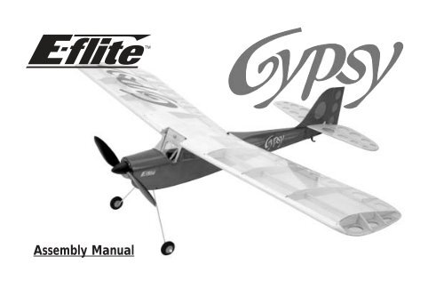
Assembly Manual
Table of ContentsIntroduction ................................................................2Table of Contents ........................................................2Warning ....................................................................3Additional Required Equipment ..................................3Additional Tools and Adhesives ..................................3Contents of Kit/Parts Layout ........................................4Warranty Information ................................................5Before Starting Assembly ............................................6Using the Manual ......................................................6Checking the Wing Washout ......................................7Attach the Wing ........................................................8Join the Vertical Fin and Horizontal Stabilizer ..............9Attach the Tail to the Fuselage ..................................12Radio Installation ......................................................14Linkage Installation ..................................................18Landing Gear Installation ..........................................22Motor Break-in ........................................................25Motor Installation ......................................................25Battery Installation ....................................................28Control Throws ........................................................29Center of Gravity ......................................................31Range Test Your Radio ..............................................322004 Official AMANational Model Aircraft Safety Code ........................34IntroductionThe <strong>Gypsy</strong> <strong>EP</strong> <strong>ARF</strong> <strong>Park</strong> <strong>Flyer</strong> is a nostalgic old timer,perfect for leisure and sport flyers who want relaxingflights. The <strong>Gypsy</strong> offers a great flying experience withexcellent climb performance, high wing stability,quality balsa and plywood construction, and qualityUltraCote ® covered with an eye catching appeal.SpecificationsWingspan: 35.25 in (895 mm)Length: 27.5 in (698.5 mm)Wing Area: 266 sq in (17.16 sq dm)Weight w/o Battery: 13.5–14.5 oz (382–411g)2
WarningAn RC aircraft is not a toy! If misused, it can causeserious bodily harm and damage to property. Fly onlyin open areas, preferably at AMA (Academy of ModelAeronautics) approved flying sites, following allinstructions included with your radio.Additional Required EquipmentRecommended JR® SystemsServos: JR 241 Sub-micro servo (2)Receiver: JR R610M 6-channel micro FM RxBattery and Speed Control RequirementsLi-Po Battery: 7.4V 1900 2-Cell7-cell Ni-MH 730mAh batterySpeed Control: 10 amp (EFLA104)Additional Tools and AdhesivesToolsSquareSide cuttersHobby knife Heat gunRulerSmall pliersPhillips screwdriver Hex wrench: 3/32"Felt-tipped penDrill bit: 1/16" (1.5mm), 1/8" (3mm)AdhesivesMedium CAOtherHeat gunMotor/Gearbox370-size with 5.33:1 gearbox (included)Propeller (10x4.7) (included)20mm diameter w/gearbox brushless (optional)3
Contents of Kit/Parts LayoutReplacement Parts:Main WingFuselageTail AssemblyWindshieldBattery HatchEFL2051EFL2052EFL2053EFL2057EFL2058Items not shown:Pushrod SetEFL2054Main Landing GearEFL2055Wheel SetEFL2056Decal SetEFL2059Micro Control HornsEFLA200Micro Pushrod KeepersEFLA201TailskidEFLA202Micro Control ConnectorsEFLA203370 Motor w/5.33:1 gearbox EFLM205Micro Rubber SpinnerEFLA20410x4.7 Slow <strong>Flyer</strong> Propeller EFLP1047Double-sided tape/Hinge Tape EFL20604
Optional Parts<strong>Park</strong> 370 Brushless Motor, 4100Kv EFLM100010x7 Slow <strong>Flyer</strong> Propeller (2) EFLP107011x4.7 Slow <strong>Flyer</strong> Propeller (2) EFLP114711x7 Slow <strong>Flyer</strong> Propeller (2) EFLP117012x3.8 Slow <strong>Flyer</strong> Propeller (2) EFLP123812x6 Slow <strong>Flyer</strong> Propeller (2) EFLP1260Celectra 1-2 cell Li-Po Charger EFLC3000Celectra 1-3 cell Li-Po Charger EFLC3005Before Starting AssemblyBefore beginning the assembly of your <strong>Gypsy</strong>, removeeach part from its bag for inspection. Closely inspectthe fuselage, wing panels, rudder and stabilizer fordamage. If you find any damaged or missing parts,contact the place of purchase.Using the ManualThis manual is divided into sections to help makeassembly easier to understand, and to provide breaksbetween each major section.Remember to take your time and follow the directions.5
Warranty InformationHorizon Hobby, Inc. guarantees this kit to be free fromdefects in both material and workmanship at the dateof purchase. This warranty does not cover anycomponent parts damage by use or modification. In nocase shall Horizon Hobby’s liability exceed the originalcost of the purchased kit. Further, Horizon Hobbyreserves the right to change or modify this warrantywithout notice.In that Horizon Hobby has no control over the finalassembly or material used for the final assembly, noliability shall be assumed nor accepted for anydamage resulting from the use of the final assembledproduct. By the act of using the assembled product, theuser accepts all resulting liability.Please note that once assembly of the model hasbeen started, you must contact Horizon Hobby, Inc.directly regarding any warranty question. Please donot contact your local hobby shop regarding warrantyissues, even if that is where you purchased it. Thiswill enable Horizon to better answer your questionsand service you in the event that you may needany assistance.If the buyer is not prepared to accept the liabilityassociated with the use of this product, the buyer isadvised to return this kit immediately in new andunused condition to the place of purchase.Horizon Hobby, Inc.4105 Fieldstone RoadChampaign, Illinois 61822(877) 504-0233www.horizonhobby.com6
Checking the Wing WashoutRequired PartsWingRequired Tools and AdhesivesHeat gun❍ 1. Place the wing on a flat surface and check thewing washout. There must be 1/2" (13mm)between the trailing edge of the wing at the tipand work surface when the center of the wingis flat against the work surface. If the wing isnot twisted correctly, hold the wing in a twistedposition and use a heat gun to remove thewrinkles from the covering. Repeat the processuntil the correct washout is present. Thewashout makes the plane more stable in flight.7
Attach the WingRequired PartsWingRequired Tools and AdhesivesHeat gunHex wrench: 3/32"❍ 2. Secure the wing to the fuselage using a 4-40 x1/2" socket head bolt and a #4 flat washer.❍ 1. Place the wing onto the fuselage by guidingthe wing dowel into the hole on theforward former.Note: The 4-40 socket head screw uses the3/32" hex wrench.8
Join the Vertical Fin and HorizontalStabilizerRequired PartsVertical finHorizontal stabilizerRequired Tools and AdhesivesMedium CASquareFelt-tipped penHobby knife❍ 1. Draw two lines on the top of the stabilizerextending back from the sides of the notch inthe front to the trailing edge. Use a square tomake the lines 90-degrees to the trailing edgeof the stabilizer.Note: The hole for the control horn will be on theleft side when the top is facing up.9
❍ 2. Carefully remove the covering along the linesusing a sharp hobby knife. Be very careful notto cut into the underlying wood and weakenthe stabilizer. If the stabilizer is weakened, itcould fail in flight.❍ 3. Align a straight edge along the bottom of thefin. Use a felt-tipped pen to draw a line ontothe lower front section of the fin. Draw lines onboth sides of the fin.10
❍ 4. Remove the covering from the lower frontsection of the fin 3/16" (5mm) below thelines drawn in the last step. Also make surethere is no covering on the bottom of the finas indicated. Leave the covering on the topforward fin as shown.❍ 5. Place the fin onto the top of the stabilizer.The positioning of the fin will be as far backin the notch as possible, aligned with thecovering removed from the stabilizer, andsquare to the stabilizer. Use medium CA toglue the fin to the stabilizer, keeping in mindthe three alignments.11
Attach the Tail to the FuselageRequired PartsTail assemblyFuselageClear tapeRequired Tools and AdhesivesMedium CAFelt-tipped penHobby knife❍ 2. Place the tail assembly onto the fuselage. Tracethe outline of the fuselage onto the stabilizerusing a felt-tipped pen.❍ 1. Carefully remove the covering from thefuselage from the slot in the top to the fuselageto the very tip of the fuselage.12
❍ 3. Separate the tail assembly from the fuselage.Remove the covering from inside the linesusing a sharp hobby knife.❍ 4. Place the tail assembly back in position. Beforeusing medium CA to attach the tail assembly tothe fuselage, stand about 10 feet away andsee if the stabilizer and wing are parallel.Apply the CA to the slot in the fuselage wherethe fin fits, and to the top of the fuselagewhere the stabilizer rests. Allow the CA to fullycure before continuing.❍ 5. Use hinge tape on both sides of the fuselageand rudder to hinge the bottom section of therudder to the fuselage13
Radio InstallationRequired PartsFuselageMicro control connector (2)Control connector backplate (2)Two-sided tape (2)Required Tools and AdhesivesPhillips screwdriverSide cuttersServo (2)Speed controlReceiverDrill bit: 1/16" (1.5mm)❍ 2. Remove the covering from the front opening onthe bottom of the fuselage. This will allowcooling air to pass through the fuselage, andwill also help when installing the servos.❍ 1. Install the servo eyelets and grommets usingthe instructions provided with your particularradio system.14
❍ 3. Connect the servos and battery to your radiosystem as shown in the radio instructions.Center the trim levers and turn on the radio.This will center the servos. It is your job toremove the servo arms and position them sothey are perpendicular to the servo.❍ 4. Locate the micro control connector andconnector backplate. Slide the connectorthrough the servo arm and secure its locationusing the connector backplate. Prepare twoservos with the connectors opposed to eachother as shown in the photo.15
❍ 5. Unplug the servos from the receiver. Removethe servo arms that are not in use, using sidecutters. Place the servos into the fuselage withthe connectors towards the outside of thefuselage, and the servo arms towards the frontof the fuselage.❍ 6. Use a 1/16" (1.5mm) drill bit to drill thelocations for the servo mounting screws.16
❍ 7. Secure the servos using the screws providedwith your radio system.❍ 8. Pass the servo leads through the opening infront of the servos. Plug the servos into thereceiver, making sure the rudder and elevatorservos are in the correct channels. Plug thespeed control into the receiver at this time too.17
❍ 9. Use two-sided tape to mount the receiver andspeed control to the sides of the fuselage.Linkage InstallationRequired PartsFuselagePushrod wire (2)Micro pushrod keeper (2)Control horn (2)Control horn backplate (2)Required Tools and AdhesivesMedium CASmall pliers❍ 1. Remove the covering in the elevator andrudder for the control horns.❍ 10. Route the receiver antenna outside thefuselage. Use tape to attach the antenna to thetail. DO NOT cut the antenna, as this willgreatly reduce the radio range.18
❍ 2. Locate one of the control horns and slide itthrough the hole in the bottom of the elevator.Secure the control horn by snapping thecontrol horn backplate onto the top of thecontrol horn. Put a couple drops of mediumCA onto the control horn backplate to preventit from coming loose in flight.❍ 3. Repeat Step 2 for the rudder control horn.Note that the rudder control horn will be onthe opposite side of the fuselage from theelevator control horn.19
❍ 4. Make an L-bend in one of the pushrod wiresusing small pliers.❍ 5. Slide the pushrod wire into the pushrod tubeon the same side as the elevator control horn.The wire will pass through the hole in themicro control connector on the elevator servo.❍ 6. Insert the L-bend in the pushrod through themiddle hole in the control horn.20
❍ 7. Slide the micro pushrod keeper onto the L-bend of the pushrod wire. The keeper thensnaps onto the pushrod wire, securing the wireto the control horn.❍ 8. Use a ruler to center the elevator in the neutralposition. With the radio system on, tighten thescrew in the micro control connector to securethe pushrod wire at the servo.❍ 9. Repeat steps 4 thought 8 to install and connectthe rudder linkage.21
Landing Gear InstallationRequired PartsFuselageMain landing gearWheels (2)Wheel retainers (2)Tailskid4-40 x 1/2" socket head cap screw#4 washerRequired Tools and AdhesivesMedium CAHex wrench: 3/32"Drill bit: 1/8" (3mm)❍ 1. Locate the main landing gear. Slide the gearinto the slot in the fuselage. Use a 4-40 x 1/2"socket head screw and #4 washer to securethe main landing gear.22
❍ 2. Slide one of the main wheels onto the landinggear. Secure the wheel using a plastic wheelretainer. A drop of medium CA on the outsideof the retainer will keep it in position. Repeatthis step for the other main wheel.❍ 3. Drill a 1/8" (3mm) hole in the bottom ofthe fuselage 2" (51mm) forward of the endof the fuselage.Note: Do not get CA between the wheel andlanding gear.23
❍ 4. Position the tailskid so the front pin is alignedwith the hole drilled in Step 3. Mark thelocation of the aft pin onto the fuselage using afelt-tipped pen.❍ 5. Drill the location made in Step 4 using a1/8" (3mm) drill bit.❍ 6. Use medium CA to glue the tailskid tothe fuselage.24
Motor Break-inRequired PartsMotorRequired Tools and AdhesivesLow voltage battery sourceIt is suggested to break-in the motor properly andto extend the life of the motor. Place a drop of oilon both the front and rear bushing of the motor,then run the motor for a few minutes on a lowervoltage source, such as 4.8 volts. This will seat thebrushes to the commutator, giving the bestperformance. Apply a drop of oil after every 5–6flights for good measure.Motor InstallationRequired PartsFuselageMotorGearbox w/motor3 x 10mm self-tapping screw (4)Required Tools and AdhesivesPhillips screwdriver❍ 1. Remove the stick mount from thegearbox assembly.25
❍ 2. Connect the motor and speed control wires.Install the gearbox into the fuselage. Use four3 x 10mm self-tapping screws to secure thegearbox to the firewall.❍ 3. Attach the propeller to the gearbox outputshaft. The single hex nut is behind thepropeller, and the washer and remaining nutare on the front side of the propeller.Note: It is highly suggested to make theadjustments to the speed control before installingthe propeller. Use the instructions provided with thespeed control for this step.Note: The text on the propeller faces the frontof the airplane.26
❍ 4. Press the safety spinner onto thegearbox output shaft.27
Battery InstallationRequired PartsFuselageBattery hatch4-40 x 1/2" socket head cap screw#4 washerRequired Tools and AdhesivesBatteryHex wrench: 3/32"❍ 1. Turn on the radio system and plug the batteryand speed control together. Place the batteryinto the battery compartment.❍ 2. Place the battery hatch onto the fuselage. Usea 3/32" hex wrench to install the 4-40 x 1/2"screw and #4 washer.28
Control ThrowsRequired PartsFuselageBatteryRequired Tools and AdhesivesRuler❍ 2. Check the movement of the elevator with theradio system. Moving the elevator stick downwill make the airplane elevator move up.❍ 1. Turn on the transmitter and receiver of your<strong>Gypsy</strong>. Check the movement of the rudderusing the transmitter. When the stick is movedright, the rudder should also move right.Reverse the direction of the servo at thetransmitter if necessary.29
❍ 3. Use a ruler to adjust the throw of the elevatorand rudder. Adjust the position of the pushrodat the control horn to achieve the flowingmeasurements when moving the sticks to theirendpoints. Moving the linkage at the controlhorn can increase or decrease the throw.Moving the linkage to the top of the horn willdecrease the throw, while moving toward thebottom of the horn will increase the throw.Elevator: 1/2" (13mm) Up 1/2" (13mm) DownRudder: 5/8" (16mm) Right 5/8" (16mm) Left30
Center of GravityAn important part of preparing the aircraft forflight is properly balancing the model.Caution: Do not inadvertently skip this step!The recommended Center of Gravity (CG) locationfor the <strong>Gypsy</strong> is 2 3 /8" (60mm) behind the leadingedge of the wing against the fuselage. Ifnecessary, move the battery pack towards the noseor the tail until the correct balance is achieved.31
Range Test Your Radio❍ 1. Before each flying session, be sure to rangecheck your radio. This is accomplished byturning on your transmitter with the antennacollapsed. Turn on the receiver in yourairplane. With your airplane on the groundand the engine running, you should be able towalk 30 paces (approximately 100 feet) awayfrom your airplane and still have completecontrol of all functions.If not, don’t attempt to fly! Have your radioequipment checked out by the manufacturer.❍ 2. Double-check that all controls (aileron,elevator, rudder and throttle) move inthe correct direction.32❍ 3. Be sure that your batteries are fully charged,per the instructions included with your radio.
Compact enough for any small park, E-<strong>flite</strong>'s electric Ascent <strong>ARF</strong> park glider is the perfect plane for experiencedpark or slow flyers who want to break into the glider set. It comes out of the box already 90% prebuilt, and thehigh-quality, lightweight fiberglass fuselage and bolt-on wing guarantee you'll spend less time building and moretime flying. It includes a sturdy Speed 400 motor that provides plenty of power. The innovative folding propeliminates drag and improves aerodyamics. And the Ascent is covered with bright, easy-to-see FluorescentTransparent Red UltraCote ® , which not only gives it a striking sheen, but also ensures you won't lose sight of it inthe sky.33
2004 Official AMANational Model Aircraft Safety CodeGENERAL1) I will not fly my model aircraft in sanctioned events,air shows or model flying demonstrations until it hasbeen proven to be airworthy by having beenpreviously, successfully flight tested.2) I will not fly my model higher than approximately400 feet within 3 miles of an airport without notifyingthe airport operator. I will give right-of-way and avoidflying in the proximity of full-scale aircraft. Wherenecessary, an observer shall be utilized to superviseflying to avoid having models fly in the proximity offull-scale aircraft.3) Where established, I will abide by the safety rulesfor the flying site I use, and I will not willfully ordeliberately fly my models in a careless, recklessand/or dangerous manner.4) The maximum takeoff weight of a model is 55pounds, except models flown under ExperimentalAircraft rules.5) I will not fly my model unless it is identified withmy name and address or AMA number, on or in themodel. (This does not apply to models while beingflown indoors.)6) I will not operate models with metal-bladedpropellers or with gaseous boosts, in which gasesother than air enter their internal combustionengine(s); nor will I operate models with extremelyhazardous fuels such as those containingtetranitromethane or hydrazine.RADIO CONTROL1) I will have completed a successful radio equipmentground range check before the first flight of a new orrepaired model.2) I will not fly my model aircraft in the presence ofspectators until I become a qualified flier, unlessassisted by an experienced helper.34
3) At all flying sites a straight or curved line(s) mustbe established in front of which all flying takes placewith the other side for spectators. Only personnelinvolved with flying the aircraft are allowed at or inthe front of the flight line. Intentional flying behind theflight line is prohibited.4) I will operate my model using only radio controlfrequencies currently allowed by the FederalCommunications Commission. (Only properly licensedAmateurs are authorized to operate equipment onAmateur Band frequencies.)5) Flying sites separated by three miles or more areconsidered safe from site-to site interference, evenwhen both sites use the same frequencies. Anycircumstances under three miles separation require afrequency management arrangement, which may beeither an allocation of specific frequencies for each siteor testing to determine that freedom from interferenceexists. Allocation plans or interference test reports shallbe signed by the parties involved and provided toAMA Headquarters. Documents of agreement andreports may exist between (1) two or more AMAChartered Clubs, (2) AMA clubs and individual AMAmembers not associated with AMA Clubs, or (3) two ormore individual AMA members.6) For Combat, distance between combat engagementline and spectator line will be 500 feet per cubic inchof engine displacement. (Example: .40 engine = 200feet.); electric motors will be based on equivalentcombustion engine size. Additional safety requirementswill be per the RC Combat section of the currentCompetition Regulations.7) At air shows or model flying demonstrations, asingle straight line must be established, one side ofwhich is for flying, with the other side for spectators.8) With the exception of events flown under AMACompetition rules, after launch, except for pilots orhelpers being used, no powered model may be flowncloser than 25 feet to any person.9) Under no circumstances may a pilot or other persontouch a powered model in flight.35
6728© 2004 Horizon Hobby, Inc.4105 Fieldstone RoadChampaign, Illinois 61822(877) 504-0233www.horizonhobby.com