Create successful ePaper yourself
Turn your PDF publications into a flip-book with our unique Google optimized e-Paper software.
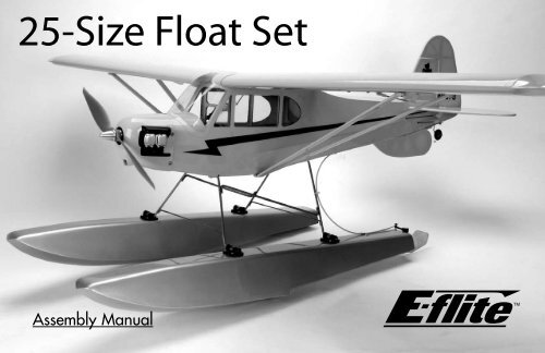
<strong>Float</strong> Installation (J-3 Cub)Required Parts• Fuselage• Landing gear• Ventral fin mount • Ventral fin• 3mm setscrew (4) • Hex wrench: 1.5mm• Nylon bracket (4)• 5/32" wheel collar (4)• 3mm x 12mm sheet metal screw (16)• 2mm x 12mm sheet metal screw (3)• Nylon strap (2)Required Tools and Adhesives• Phillips screwdriver • File or rotary tool• Threadlock• Hobby knife• 6-minute epoxy 1. Remove the packing material from the landinggear. Attach it to the fuselage using the twonylon straps that were used to hold on the maingear and the two nylon straps included with thefloat kit. Use 2mm x 12mm screws to install thenylon straps.
2. Attach two of the brackets to each float usingeight 3mm x 12mm sheet metal screws. Eachfloat uses two brackets, so you’ll install fourbrackets in all. 3. Use a file or rotary tool to make a flat on the topof each of the landing gear extensions.
4. Attach the floats using the four 5/32" wheelcollars and four 3mm setscrews. Make sure to usethreadlock when tightening the setscrews onto theflats made in the previous step.Note: One float has holes drilled in the aft endfor the rudder bracket. This float is mounted onthe same side as the rudder linkage.
5. Attach the ventral fin mount using three 2mm x12mm sheet metal screws. 6. Remove the bottom 1/8" (3mm) of covering fromthe ventral fin using a hobby knife.10
7. Attach the ventral fin to the mount using 6-minuteepoxy. Make sure the fin is in line with the verticalcenterline of the fuselage.Linkage InstallationRequired Parts• Fuselage w/floats • Nylon bracket• Steering arm • 5/32" wheel collar• 3mm setscrew (2) • Pushrod connector (2)• Tie wrap• Half brass strap• Full brass strap (3) • Connector backplate (2)• Rudder shaft assembly• 3mm x 12mm sheet metal screw (4)• 29 3 / 4 " (755mm) pushrod cable• <strong>25</strong> 3 / 4 " (655mm) pushrod tube• 2mm x 10mm sheet metal screw (7)Required Tools and Adhesives• Phillips screwdriver • Hobby knife• Pliers• Threadlock• Drill• Drill bit: 5/64" (2mm)• Hex wrench: 1.5mm, 3/32”11
1. Attach a nylon bracket to the rear of the floatusing four 3mm x 12mm sheet metal screws. 2. Place a 5/32" wheel collar in the center of thenylon bracket. Slide the rudder assembly throughthe nylon bracket and the wheel collar. Secure thesteering arm at the top and the wheel collar using3mm setscrews.Note: Remember to use threadlock on .both setscrews.12
3. Enlarge the middle hole in the steering armwith a 5/64" (2mm) drill bit. Secure a pushrodconnector on the steering arm using a pushrodconnector backplate. 4. Enlarge the outboard hole in the rudder controlhorn using a 5/64" (2mm) drill bit. Secure apushrod connector on the rudder horn using apushrod connector backplate.13
5. With the pushrod cable inside the pushrod tube,attach the tube to the float using a full brass strapand two 2mm x 10mm sheet metal screws. Theend of the pushrod tube is 1 1 / 2 " (38mm) fromthe end of the float. 6. Use two full brass straps and the half brass strapto attach the pushrod tube to the bottom of thefuselage. Leave the straps slightly loose so it canbe moved around for the next step.Note: These straps are secured onto thecrossbraces on the bottom of the fuselage.14
7. Use a tie wrap to attach the pushrod tube to thelanding gear. Slide the tube as necessary. Onceattached, go back and tighten the screws for thebrass straps. 8. With the rudder centered, secure the pushrodcable using a 3mm setscrew. Place the steeringarm parallel with the end of the float andsecure the cable at the steering arm end usinga 3mm setscrew.15
9. Position the water rudder parallel to the rudderof the aircraft. It may be necessary to loosen thesetscrew at the steering arm to do so. 10. Test the operation of the water rudder with theaircraft rudder. The water rudder will move leftwhen the aircraft rudder moves left, and rightwhen the aircraft rudder moves right. 11. Adjust the water rudder to move up and downby tightening or loosening the 4-40 sockethead screw on the rudder shaft. The waterrudder should be able to deflect up if it hits anobstruction in the water. 12. Now that your floats have been installed, youMUST verify that the Center of Gravity of yourmodel is still correct. Use the Center of Gravityprovided in the manual included with yourparticular aircraft.16
<strong>Float</strong> Installation (Ultra Stick <strong>25</strong>e)Required Parts• Fuselage• Landing gear• 3mm setscrew (4)• Nylon bracket (4)• 4-40 x 1/2" socket head screw (3)• 5/32" wheel collar (4)• 3mm x 12mm sheet metal screw (16)Required Tools and Adhesives• Phillips screwdriver • File or rotary tool• Threadlock• Hobby knife• Hex wrench: 3/32"Note: The Ultra Stick <strong>25</strong>e comes with thenecessary landing gear mounts for theinstallation of the floats. You will also find 4molded 3.5mm spacer blocks in the Ultra Stick<strong>25</strong>e kit which will be used when mounting thefloat mounts onto the floats. Use these parts inaddition to the float hardware to complete theinstallation. 1. Locate the holes on the fuselage for the rearlanding gear. These are located behind the airexit on the fuselage. Use a hobby knife toremove the covering. Attach the landing gearto the fuselage using three 4-40 x 1/2" sockethead screws.17
2. Remove the wheels and wheel collars from themain gear. 3. Attach two of the brackets and float mounts toeach float using eight 3mm x 12mm sheet metalscrews. Each float uses two brackets and two floatmounts, so you'll install eight pieces in all.18
4. Use a file or rotary tool to make a flat on the topof each of the four axles. 5. Attach the floats using the four 5/32" wheelcollars and four 3mm setscrews. Make sure to usethreadlock when tightening the setscrews onto theflats made in the previous step.19
Note: One float has holes drilled in the aft endfor the rudder bracket. This float is mounted onthe same side as the rudder linkage.Linkage InstallationRequired Parts• Fuselage w/floats • Nylon bracket• Steering arm • 5/32" wheel collar• 3mm setscrew (4) • Pushrod connector (2)• Rudder shaft assembly • Tie wrap• Full brass strap (3) • Connector backplate (2)• 3mm x 12mm sheet metal screw (4)• 29 3 / 4 " (755mm) pushrod cable• <strong>25</strong> 3 / 4 " (655mm) pushrod tube• 2mm x 10mm sheet metal screw (6)Required Tools and Adhesives• Phillips screwdriver • Hobby knife• Pliers• Threadlock• Drill• Drill bit: 5/64" (2mm)• Hex wrench: 1.5mm, 3/32”20
1. Attach a nylon bracket to the rear of the floatusing four 3mm x 12mm sheet metal screws. 2. Place a 5/32" wheel collar in the center of thenylon bracket. Slide the rudder assembly throughthe nylon bracket and the wheel collar. Secure thesteering arm at the top and the wheel collar using3mm setscrews.Note: Remember to use threadlock on .both setscrews.21
3. Enlarge the middle hole in the steering armwith a 5/64" (2mm) drill bit. Secure a pushrodconnector on the steering arm using a pushrodconnector backplate. 4. Enlarge the outboard hole in the rudder controlhorn using a 5/64" (2mm) drill bit. Secure apushrod connector on the rudder horn using apushrod connector backplate.22
5. With the pushrod cable inside the pushrod tube,attach the tube to the float using a full brass strapand two 2mm x 10mm sheet metal screws. Theend of the pushrod tube is 1 1 / 2 " (38mm) from theend of the float. 6. Bend two full brass straps to attach the pushrodtube to the top of the fuselage. Leave the strapsslightly loose so it can be moved around for thenext step.23
7. Use a tie wrap to attach the pushrod tube to thelanding gear. Slide the tube as necessary. Onceattached, go back and tighten the screws for thebrass straps. 8. With the rudder centered, secure the pushrodcable using a 3mm setscrew. Place the steeringarm parallel with the end of the float andsecure the cable at the steering arm end usinga 3mm setscrew.24
9. Position the water rudder parallel to the rudderof the aircraft. It may be necessary to loosen thesetscrew at the steering arm to do so. 10. Test the operation of the water rudder with theaircraft rudder. The water rudder will move leftwhen the aircraft rudder moves left, and rightwhen the aircraft rudder moves right. 11. Adjust the water rudder to move up and downby tightening or loosening the 4-40 sockethead screw on the rudder shaft. The waterrudder should be able to deflect up if it hits anobstruction in the water. 12. Now that your floats have been installed, youMUST verify that the Center of Gravity of yourmodel is still correct. Use the Center of Gravityprovided in the manual included with yourparticular aircraft.<strong>25</strong>
<strong>Float</strong> FlyingFlying from floats can be great fun. There are a few thingsto remember when you hit the lake. First, make sure youpick a location where you can take off and land parallelto the shore line with no obstructions. You will want tomake sure you are taking off and landing into the wind.Verify your water rudder is down and the plane ispowered up. <strong>Set</strong> the plane into the water and begin totaxi out. It is common to hold full up elevator (back stick)during all taxi maneuvers. This helps to eliminate propsplash and keeps the water rudder deep in the water forimproved steering. You may want to use a high rate foryour rudder during this operations as well. You will switchto a low rate rudder for takeoff.Taxi slow to get the hang of the rudder. Once you havelined up for takeoff, set your rudder dual rate to low. Thewater rudder becomes very effective during takeoff. Applyfull up elevator and apply throttle slowly at first. As theplane picks up speed, you will notice it coming up on step.At this time, you can relax the elevator input and fly offthe water the same way you take off from hard ground.Once in the air, you will find the plane to behave slightlydifferent that before. The added weight below the modelacts similar to a pendulum effect in flight. It will slightlyeffect the aerobatic performance as well. You will notice ahigher power setting from normal due to the added dragand weight of the floats.26
Landing on water is very similar to landing on hardground. <strong>Set</strong> up like you normally would and turn ontofinal approach. Maintain power during the approach,as a plane with floats tends to land slightly faster thanwhen equipped with landing gear. As you come down,begin to flair and hold it until touchdown. Once youhave touched down on the water, as the plane slowsdown, begin to feed in up elevator as the plane settles.Once you are slowed down, taxi back to shore and getready for another day at the lake.Please refer to the instruction manual for the J-3 Cub orUltra Stick <strong>25</strong>e for further information on flying with floats.We hope you enjoy flying off water as much as we do.Happy <strong>Float</strong> Flying.<strong>Float</strong> Flying27
2006 Official AMA National Model Aircraft Safety CodeGENERAL1) I will not fly my model aircraft in sanctioned events,air shows or model flying demonstrations until ithas been proven to be airworthy by having beenpreviously, successfully flight tested.2) I will not fly my model higher than approximately400 feet within 3 miles of an airport without notifyingthe airport operator. I will give right-of-way and avoidflying in the proximity of full-scale aircraft. Wherenecessary, an observer shall be utilized to superviseflying to avoid having models fly in the proximity offull-scale aircraft.3) Where established, I will abide by the safety rulesfor the flying site I use, and I will not willfully ordeliberately fly my models in a careless, reckless and/or dangerous manner.4) The maximum takeoff weight of a model is 55pounds, except models flown under ExperimentalAircraft rules.5) I will not fly my model unless it is identified withmy name and address or AMA number on or in themodel. (This does not apply to models while beingflown indoors.)6) I will not operate models with metal-bladedpropellers or with gaseous boosts, in which gasesother than air enter their internal combustionengine(s); nor will I operate models with extremelyhazardous fuels such as those containingtetranitromethane or hydrazine.RADIO CONTROL1) I will have completed a successful radio equipmentground range check before the first flight of a new orrepaired model.2) I will not fly my model aircraft in the presenceof spectators until I become a qualified flier, unlessassisted by an experienced helper.28
2006 Official AMA National Model Aircraft Safety Code3) At all flying sites a straight or curved line(s) mustbe established in front of which all flying takes placewith the other side for spectators. Only personnelinvolved with flying the aircraft are allowed at or infront of the flight line. Intentional flying behind theflight line is prohibited.4) I will operate my model using only radio controlfrequencies currently allowed by the FederalCommunications Commission. (Only properly licensedAmateurs are authorized to operate equipment onAmateur Band frequencies.)5) Flying sites separated by three miles or moreare considered safe from site-to-site interference,even when both sites use the same frequencies. Anycircumstances under three miles separation require afrequency management arrangement, which may beeither an allocation of specific frequencies for each siteor testing to determine that freedom from interferenceexists. Allocation plans or interference test reports shallbe signed by the parties involved and provided toAMA Headquarters.Documents of agreement and reports may existbetween (1) two or more AMA Chartered Clubs,(2) AMA clubs and individual AMA members notassociated with AMA Clubs, or (3) two or moreindividual AMA members.6) For Combat, distance between combat engagementline and spectator line will be 500 feet per cubic inchof engine displacement. (Example: .40 engine = 200feet.); electric motors will be based on equivalentcombustion engine size. Additional safety requirementswill be per the RC Combat section of the currentCompetition Regulations.7) At air shows or model flying demonstrations, asingle straight line must be established, one side ofwhich is for flying, with the other side for spectators.8) With the exception of events flown under AMACompetition rules, after launch, except for pilots orhelpers being used, no powered model may be flowncloser than <strong>25</strong> feet to any person.9) Under no circumstances may a pilot or other persontouch a powered model in flight.29
30Notes
Notes31
8688© 2006 Horizon Hobby, Inc.4105 Fieldstone RoadChampaign, Illinois 61822(877) 504-0233horizonhobby.comE-<strong>flite</strong>RC.com


