Equi-Flow Valve IFU
Equi-Flow Valve IFU
Equi-Flow Valve IFU

You also want an ePaper? Increase the reach of your titles
YUMPU automatically turns print PDFs into web optimized ePapers that Google loves.
ACKNOWLEDGEMENTSThis report was researched and written by TheEnvironmental Integrity Project’s Senior ManagingAttorney, Mary Greene.THE ENVIRONMENTAL INTEGRITYPROJECTThe Environmental Integrity Project (EIP) is anonpartisan, nonprofit organization established inMarch of 2002 by former EPA enforcement attorneysto advocate for effective enforcement of environmentallaws. EIP has three goals: 1) to provide objectiveanalyses of how the failure to enforce or implementenvironmental laws increases pollution and affectspublic health; 2) to hold federal and state agencies, aswell as individual corporations, accountable for failingto enforce or comply with environmental laws; and3) to help local communities obtain the protection ofenvironmental laws. Visit our website athttp://www.environmentalintegrity.org.For questions about this report, contact Director ofCommunications Tom Pelton at (202) 888-2703 ortpelton@environmentalintegrity.org.PHOTO CRE DI TSPhoto on the cover of drilling rig was purchased from iStockphoto, as werethe photos on pages 4, 6, 7, 14, and 16 and the back cover.Aerial photographs on pages 1, 5, and 6 of this report were taken of sites insouthwest Pennsylvania by Robert Donnan for the Environmental IntegrityProject.Photo on page 2 from the Monroe County (Ohio) Emergency ManagementAgency.Map of Pennsylvania on page 13 reprinted with permission from the PittsburghPost-Gazette. Copyright ©, Pittsburgh Post-Gazette, 2014, all rights reserved.
Figure 1/Figure 1/Abbildung 1/Figura 1/Figura 1 (Continued)Captions/Légendes/Bildtexte/Didascalie/Textos• Pressure/Pression/Druck/Pressione/Presión• Water Hydrostatic Pressure/Pression Hydrostatique/Hydrostatischer Wasserdruck/Acqua Pressione/Presión Hidrostática de Agua• <strong>Flow</strong> Rate (ml/hr)/Débit (ml/h)/Flussrate (ml/Std.)/Flusso (ml/ora)/Velocidad de Flujo (ml/h)Performance Level 1.5Niveau de Performance 1,5Leistungsebene 1,5Livello di Prestazione 1,5Nivel de Funcionamiento 1,5Performance Level 2.0Niveau de Performance 2,0Leistungsebene 2,0Livello di Prestazione 2,0Nivel de Funcionamiento 2,03
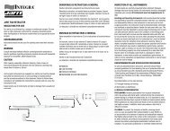
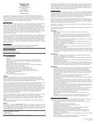
EnglishOccluderSiliconeDomeReservoirTantalumPressureDotsTantalumDirectionalArrowOccluderSiphonLimitingDeviceInletConnectorReinforcedSheetingPolypropyleneNeedle GuardSiliconeMembraneOutletConnectorDESCRIPTIONThe Integra <strong>Equi</strong>-<strong>Flow</strong> <strong>Valve</strong> is a multi-function membrane valve incorporating a normally open Siphon LimitingDevice, occluders, and integral tubing connectors. It is used in treatment of patients with hydrocephalus when shuntingcerebrospinal fluid (CSF) from ventricles of the brain. It incorporates a central reservoir for pumping and injection,proximal and distal occluders, a Siphon Limiting Device and a fully flexible profile. The Siphon Limiting Device limitsthe reduction of intraventricular pressure and volume caused by the siphoning effect of hydrostatic pressure in the DistalCatheter.The <strong>Equi</strong>-<strong>Flow</strong> <strong>Valve</strong> design includes a flat silicone membrane, which provides resistance to CSF flow. The flat siliconemembrane seats on a conical polypropylene base which is integral to the Siphon Limiting Device. The Siphon LimitingDevice contains a rigid outlet port. This design allows for accurate and precise regulation of CSF flow due to itsstructural integrity. The flat silicone membrane also prevents retrograde flow of CSF.The <strong>Equi</strong>-<strong>Flow</strong> <strong>Valve</strong> is available in two sizes: Regular and Small. Both sizes are available in 4 pressure/flowcharacteristics ranges: Performance levels 0.5, 1.0, 1.5 and 2. The pressure/flow characteristics of both sizes of theIntegra <strong>Equi</strong>-<strong>Flow</strong> <strong>Valve</strong> are shown in the graph (Figure 1) and chart (Figure 3). These pressure values are derived as thevalve is tested at flow rates varying from 5 to 50 ml/hr. Each valve is individually tested to obtain its pressure/flowcharacteristics, closing pressure (Figure 2), and its ability to prevent retrograde fluid flow. The tantalum impregnatedsilicone arrow and pressure dot code on the valve housing allow identification of the pressure/flow rating. Each valve isdot-coded based on its horizontal and vertical operating pressures measured at the time of manufacture. The pressure ofeach valve has been verified to be within the pressure range limits indicated on the package label.The <strong>Equi</strong>-<strong>Flow</strong> <strong>Valve</strong> is designed with a fully flexible profile to conform to the curvature of the skull.The <strong>Valve</strong>’s integral tubing connectors present an outer diameter of 1.8 mm for connection to standard catheters.The <strong>Equi</strong>-<strong>Flow</strong> <strong>Valve</strong> may be flushed in either the proximal or distal direction by pressing one of the occluders on thevalve and pressing the reservoir. The reservoir is designed to allow penetration with a 25-gauge or smaller beveledneedle. The reservoir contains a polypropylene needle guard to prevent overpenetration of the needle. The valvemembrane is further protected from needle punctures by a rigid polypropylene cartridge.Magnetic Resonance Imaging (MRI)/CT CompatibilityThe <strong>Equi</strong>-<strong>Flow</strong> <strong>Valve</strong> is made of materials that are known not to interfere with CT scans or MRI imaging. Caution shouldbe exercised to ensure that the device is not connected to components that may contain interfering or non-compatiblematerials.MaterialsThe entire bottom surface of the <strong>Equi</strong>-<strong>Flow</strong> <strong>Valve</strong> is constructed of barium-sulfate impregnated silicone elastomer. It alsocontains polyester reinforced sheeting, which is fully encapsulated by silicone elastomer to prevent contact with tissuesor fluids. The <strong>Equi</strong>-<strong>Flow</strong> <strong>Valve</strong> is latex free.Materials in contact with body tissues or body fluids are silicone elastomer with or without barium sulfate,polypropylene with or without barium sulfate, silicone ink and stainless steel.ConfigurationsThe System is available in different configurations; a system generally consists of a ventricular (proximal) catheter, avalve unit, and a drainage (distal) catheter. The drainage catheter may be integral (attached to the valve) or separate.Some configurations contain a burr hole cap and a burr hole reservoir. Included with the <strong>Equi</strong>-<strong>Flow</strong> shunt systems thathave a ventricular catheter are one introducing rod (stylet) and one Right-Angle Guide (RAG).4
EnglishVentricular Catheters feature numbered length markers located 5 and 10 cm from the proximal end. Length marker dotsare located at 1 cm increments 3 to 14 cm from the proximal end. The proximal end contains fourty (40) flow holes.Distal Catheter are 91 cm silicone elastomer barium sulfate striped tubings. Numbered length markers are located 5, 10,15, 20, 25 and 30 cm from the distal end to assist catheter placement. The distal end of the catheter has four staggeredrows of 5.5-mm slits, which are not easily visible.Burr Hole Reservoirs are made of radiopaque polypropylene and measure 6.4 mm in diameter and 0.8 mm in depth.INDICATIONSThe Integra <strong>Equi</strong>-<strong>Flow</strong> <strong>Valve</strong> and Shunt Systems are used in the treatment of patients with hydrocephalus. The device isdesigned to shunt cerebrospinal fluid from the ventricles of the brain to an appropriate drainage site, such as the atrium ofthe heart or to the peritoneal cavity. The <strong>Equi</strong>-<strong>Flow</strong> <strong>Valve</strong> is indicated in patients where excessive reduction ofintraventricular pressure or volume may be caused by the siphoning effect of hydrostatic pressure in the distal catheter ofthe shunt system.CONTRAINDICATIONSHydrocephalus shunt systems should not be implanted when the patient has known or suspected infections in the vicinityof any of the implanted components (meningitis, ventriculitis, skin infections, bacteremia, septicemia, peritonitis, etc.).Avoid implanting hydrocephalus shunt systems if infection is present anywhere in the body. Shunting into the atrium ofpatients with congenital heart disease or other cardiopulmonary anomalies is contraindicated.WARNINGS:• Patients with hydrocephalus shunt systems should be closely observed postoperative for signs and symptomsof shunt obstruction or overdrainage of CSF.• Obstruction of the shunt system may lead to signs and symptoms of increased intracranial pressure. For aninfant, the signs may be increased tension on the fontanelle, congestion of scalp veins, listlessness,drowsiness, nuchal rigidity, irritability, and vomiting. For older patients, the signs may be headaches,vomiting, diminished consciousness, nuchal rigidity, and blurred vision.• Overdrainage by the shunt system may lead to signs and symptoms of reduced intracranial pressure and thedevelopment of a subdural hematoma, subdural hygroma, or collapse of the lateral ventricular walls leadingto obstruction of the Ventricular Catheter.• Shunt obstruction or overdrainage requires immediate surgical intervention. The surgeon is advised to usetechniques to which he/she is accustomed.• The Ventricular Catheter may become bound to the choroid plexus or by fibrous tissue. Use gentle rotationto free it. Forcible removal of the catheter may result in an intraventricular hemorrhage.• Placement of the distal catheter into the right atrium of the heart may lead to embolization of thepulmonary arterial tree with resulting corpulmonale and pulmonary hypertension.PRECAUTIONS• Patients or their representatives should be informed of the warnings and potential complications associated with useof this device prior to implantation.• Avoid cutting or occluding catheter tubing when securing tubing to valve connector with ligatures. Do not kinkcatheters at any point. Other than trimming catheters or valve tubing, modifications are not recommended.• Avoid use of sharp metal instruments when handling silicone components to avoid any damage.• If a hypodermic injection into the reservoir is required, use a 25-gauge or smaller beveled needle and only inject intothe reservoir dome.• Have duplicates of each component available during implantation.• Do not lubricate valves. They will be lubricated adequately by the CSF.• Avoid contaminants such as glove talc and contact with skin oils when handling tubing.• Do not puncture the Siphon Limiting Device with a needle.• Do not place the <strong>Equi</strong>-<strong>Flow</strong> <strong>Valve</strong> under the skin of the neck, chest or abdomen.COMPLICATIONSComplications associated with use of this device may be similar to those associated with medication and anestheticmethods used in other surgical procedures, as well as the patient’s degree of reaction or sensitivity to any foreign objectimplanted in the body.Common complications associated with the shunt system itself may include shunt obstruction, infection, mechanicalfailure of system components, and excessive lowering of intracranial pressure.5
EnglishKinking of the catheters may cause mechanical failure and result in obstruction of the shunt system. Shunt obstructions inthe Ventricular Catheter are commonly caused by particulate matter, blood clots, fibrin, tumor cell aggregates, etc. TheVentricular Catheter may become obstructed by being bound by choroid plexus, embedded within the brain, or bycoaptation of ventricular walls. Shunt obstructions in the Distal Catheter are commonly caused by particulate matter,blood clots, debris, tumor cell aggregates within the lumen, adhesions surrounding slit openings at the tip, bacterialcolonization, or withdrawal of catheter from the atrium or peritoneal cavity due to the growth of the infant or child.Placement of the Distal Catheter into the peritoneal cavity may result in obstruction due to intraluminal debris,investment in the greater omentum or bowel, or perforation of surrounding tissues.Growth of the infant or child may result in Distal Catheter withdrawal from the atrium into the jugular vein or from theperitoneal cavity into tissue planes where fluid cannot be easily absorbed.Local or systemic infection is a common and serious adverse effect of shunt implantation, and is primarily caused by skincontaminations at the surgical wound site. However, infections can also be caused by pathogens circulating in thebloodstream and/or skin lesions arising from irritation and breakdown of skin over the implanted shunt. Ventriculoatrialshunting may predispose the spread of bacteria to other areas of the body including vital organs.Mechanical failure of the shunt system may occur if any components become disengaged or fractured. This may alsoresult in migration of shunt components into the peritoneal cavity, the right atrium, lateral ventricle of the brain, orsurrounding areas.Placement of the distal catheter into the right atrium of the heart may lead to embolization of the pulmonary arterial treewith resulting corpulmonale and pulmonary hypertension.The incidence of epilepsy has been reported with the use of hydrocephalus shunt systems. Also, the incidence of seizureshas increased with multiple catheter revisions.In the infant, excessive reduction of CSF pressure will cause marked depression of the anterior fontanelle. It may alsocause overriding of cranial bones and change communicating into non-communicating hydrocephalus.HOW SUPPLIEDIntegra <strong>Equi</strong>-<strong>Flow</strong> <strong>Valve</strong> and Shunt Systems are supplied sterile and non-pyrogenic in a double-wrap packaging.This product is for single use only. Do not reuse. This product is sterilized with ethylene oxide. Do not use if the packageis open or damaged. Use the device prior to the "Use by" date on the package label.Caution - Do not resterilize. Integra will not be liable for any direct, indirect, incidental, consequential or punitivedamages resulting from or related to resterilization.INSTRUCTIONS FOR USESurgical ProcedureThe implantation of a shunt system including placement of the Ventricular Catheter, Distal Catheter, and <strong>Valve</strong> may beaccomplished through a variety of surgical techniques. The surgeon is best advised to use the method which his/her ownpractice and discretion dictate to be best for the patient.It is recommended the valve be placed in a surgically created subgaleal pocket and not under a scalp incision. The valveshould not be placed under the skin of the neck, chest or abdomen.Ventricular Catheter PlacementIt is recommended that catheter insertion is the last step of the shunt placement to minimize CSF loss during theprocedure. For systems with burr hole cap and reservoir, the burr hole should be larger than 6.5 mm.A stainless steel sytlet is provided with the catheter, inserted in the central lumen, to assist its introduction into theventricle. Once the catheter is placed the stylet can be removed from the catheter.If the right angle guide is used, follow these steps:1. The right angle guide may be used as a marker to plan the depth of catheter insertion. Prior to insertion, slide theright angle guide the approximate desired distance from the proximal tip of catheter.2. Use the right angle guide to bend the Ventricular Catheter at a right angle where it exits the twist drill or burr hole.3. After placement of the Ventricular Catheter, press the extracranial portion of the catheter into the split tubularsegment of the right angle guide to form a right angle bend. Wetting the catheter with sterile isotonic fluid mayfacilitate sliding the right angle guide over the catheter.6
English4. Secure the right angle guide to surrounding tissue with sutures.Note: If the right angle guide is not used, it may be removed at the time of surgery. It is recommended that thesurgeon trim the rim of the twist drill or burr hole to provide a beveled notch for proper catheter curvature.Distal Catheter Patency CheckPrior to use, check distal end of catheter to ensure slits are open. This is accomplished through the following:1. Using thumb and forefinger, hold the section of catheter containing slits. Gently roll catheter slits between thumband forefinger.2. Next, hold catheter on both sides of slits, then push slits together.3. Once again, gently roll slits between thumb and forefinger to ensure all slits are properly seated.To flush Distal Catheter before use, insert a full syringe of sterile fluid (e.g. irrigation water, physiological saline) intoproximal end of catheter, and gently flush. A blunt 17-gauge needle may be used if necessary.Distal Catheter PlacementDuring implantation, the proximal end of catheter may be trimmed to the appropriate length required for its particular use(Note: This applies to shunts with a separate Distal Catheter only). The distal end may be trimmed if wall slits are notrequired.Integra subcutaneous catheter passers are available for tunneling of the catheter.Assembling the Shunt1. To connect Ventricular Catheter to the valve, insert valve’s proximal connector into open end of catheter. Forsystems with burr hole cap, a burr hole reservoir is provided already connected to the cap: ensure the assembly iscorrectly connected and insert the ventricular catheter into the burr hole reservoir. Ensure catheter covers theentire connector.2. Secure the connection with an encircling ligature.Note: If the Distal Catheter is not pre-attached to valve, follow steps 3 and 4 below.3. Insert valve’s distal connector into open end of catheter. Ensure Distal Catheter covers the entire connector.4. Secure the connection with an encircling ligature.InjectionThe reservoir is designed to allow penetration with a 25-gauge, or smaller, beveled needle. The reservoir contains apolypropylene needle guard to prevent overpenetration of the needle. The valve membrane is protected from needlepunctures by a polypropylene cartridge. However, care should be taken to avoid this area when inserting a needle.Puncturing the valve membrane may affect the pressure/flow characteristics of the valve.Note: Neither catheter tubing nor occluders should be used as injection sites.CAUTION: Low tear strength is a natural property of most non-reinforced silicone materials. Use care duringinsertion and removal of the needle. Insert needle at an angle approximately 45° from the scalp or base of thevalve. If valve reservoir is to be punctured several times, insert needle at different locations to avoid multiplepunctures at a single point. Take care not to puncture the Siphon Limiting Device.Flushing the <strong>Valve</strong>1. To flush CSF from valve in both distal and proximal directions, use finger pressure to transcutaneaously depress thereservoir.2. To flush in one direction only, depress the occluder opposite the reservoir from the catheter to be flushed, and pumpreservoir.Note: A reservoir dome with noticeable resistance to compression could indicate an occluded catheter.CAUTION: Avoid unnecessary testing and pumping of valve. Frequent pumping can lead to overdrainage of theventricles, particularly if ventricle size is small.Pre-Implant <strong>Valve</strong> Patency Test1. Place inlet connector of valve into sterile fluid (e.g. irrigation water, physiological saline).2. Repetitively depress reservoir until fluid flows from valve’s outlet connector. <strong>Valve</strong> is patent if fluid flows fromoutlet connector with each press of the reservoir.3. Ensure diaphragm of Siphon Limiting Device opens completely. If diaphragm does not open completely, gentlysqueeze sides of Siphon Limiting Device and repeat test.7
English4. Finally, be sure to remove all large bubbles from the shunt system. It is not necessary to remove small bubbles.Note: If Distal Catheter slits are stuck together, fill the shunt system with sterile fluid, then roll slits gently betweenfingers to lubricate and open the slits.Note: To perform an alternative patency test, attach a syringe to the valve’s proximal inlet connector and gentlyflush with sterile fluid.Pre-Implant <strong>Valve</strong> Pressure TestEvery Integra <strong>Equi</strong>-<strong>Flow</strong> <strong>Valve</strong> is individually tested to ensure it meets rigorous specifications and pressure/flowcharacteristics. If, however, the surgeon wishes to verify the closing pressure of the valve is as stated in thespecifications, the following procedure may be performed in the operating room.CAUTION: Use extreme care to maintain sterility and avoid particulate contamination.<strong>Equi</strong>pment needed (sterile)1. Fluid reservoir or water bath2. 30 cm or larger manometer, graduated in centimeters wih a 3-way stopcock3. 30 cc – 60 cc syringe4. Tubing5. Blunt needle to connect syringe to tubing6. Sterile distilled water or physiological salineTest procedure1. Connect tubing to both sides of the manometer.2. Place one tube into water bath.3. Align the manometer so the zero mark is level with fluid in the water bath.4. Purge all air from system by flushing with syringe.5. Attach the proximal connector of valve to be tested to the tube submerged in water bath.6. Gently flush valve with sterile fluid and submerge completely in the water bath.7. Fill manometer to approximately 30 cm H 2 O.8. While maintaining a gentle flow of fluid through valve using the syringe, isolate syringe from valve with the 3-waystopcock.9. The water column will begin to fall as fluid flows through valve. After 2 – 2.5 minutes, read fluid level inmanometer. The valve must be submerged in the water bath to obtain the correct results.Closing Pressure ResultsPerformance Level (Regular or Small)Acceptable Closing Pressure<strong>Flow</strong> Rate0.5 1.0 – 5.0 cm H 2 O1.0 1.0 – 7.0 cm H 2 O1.5 3.5 – 9.5 cm H 2 O2.0 5.0 – 13.0 cm H 2 OFig. 2Pressure/<strong>Flow</strong> CharacteristicsPerformance Level0.5 1.0 1.5 2.05 ml/hr, 0 cm H 2 O Hydrostatic Pressure 1-4 cm H 2 O 1-7 cm H 2 O 4.5-9.5 cm H 2 O 6-13 cm H 2 O50 ml/hr, 0 cm H 2 O Hydrostaticpressure5 ml/hr, -50 cm H 2 O HydrostaticPressure50 ml/hr, -50 cm H 2 O HydrostaticPressure<strong>Valve</strong> Marking2-6 cm H 2 O 2-9 cm H 2 O 6.5-11.5 cm H 2 O 8-14 cm H 2 O1-6.5 cm H 2 O 1-9.5 cm H 2 O 4.5-12.5 cm H 2 O 6-15.5 cm H 2 O2-8.5 cm H 2 O 2-11.5 cm H 2 O 6.5-14.5 cm H 2 O 8-17 cm H 2 OFig. 38
EnglishPRODUCT INFORMATION DISCLOSUREINTEGRA HAS EXERCISED REASONABLE CARE IN THE SELECTION OF MATERIALS AND THEMANUFACTURE OF THESE PRODUCTS. INTEGRA EXCLUDES ALL WARRANTIES, WHETHER EXPRESSEDOR IMPLIED, INCLUDING BUT NOT LIMITED TO, ANY IMPLIED WARRANTIES OF MERCHANTABILITYOR FITNESS FOR A PARTICULAR PURPOSE. INTEGRA SHALL NOT BE LIABLE FOR ANY INCIDENTAL ORCONSEQUENTIAL LOSS, DAMAGE, OR EXPENSE, DIRECTLY OR INDIRECTLY ARISING FROM USE OFTHIS PRODUCT. INTEGRA NEITHER ASSUMES NOR AUTHORIZES ANY PERSON TO ASSUME FOR IT ANYOTHER OR ADDITIONAL LIABILITY OR RESPONSIBILITY IN CONNECTION WITH THESE PRODUCTS.Returned Goods PolicyProducts must be returned in unopened packages with manufacturer’s seals intact to be accepted for replacement or creditunless returned due to a complaint of product defect.Determination of a product defect will be made by Integra.Products will not be accepted for replacement if they have been in the possession of the customer for more than 90 days.Product Order InformationAll products can be ordered through your Integra NeuroSpecialist or customer service representative or by contacting:Integra NeuroSciences311 Enterprise DrivePlainsboro, NJ 08536, USATelephone: 1-800-654-2873Outside the US: 1-609-275-0500Fax: 1-609-275-5363Integra NeuroSciences Implants S.A.2905 Route des Dolines06921 Sophia Antipolis cedex, FranceTelephone: +33 4 93 95 56 00Fax: +33 4 93 65 40 30Integra NeuroSciences LtdNewbury RoadAndoverHampshire SP10 4DR, EnglandTelephone: +44 (0) 1264 345 700Fax: +44 (0) 1264 332 1139