CEBAF 12 GeV Personnel Safety Systems - JLab Tech Notes Home ...
CEBAF 12 GeV Personnel Safety Systems - JLab Tech Notes Home ...
CEBAF 12 GeV Personnel Safety Systems - JLab Tech Notes Home ...

Create successful ePaper yourself
Turn your PDF publications into a flip-book with our unique Google optimized e-Paper software.
<strong>CEBAF</strong> <strong>12</strong> <strong>GeV</strong> <strong>Personnel</strong> <strong>Safety</strong> <strong>Systems</strong> – PreliminaryDesign1 <strong>CEBAF</strong> at <strong>12</strong> <strong>GeV</strong>The <strong>CEBAF</strong> upgrade to <strong>12</strong> <strong>GeV</strong> will include extending the present <strong>CEBAF</strong> safety systems inthe accelerator and add a “Tagger/Hall D” PSS segment. This note describes the intendedequipment and modifications to the existing <strong>JLab</strong> PSS.2 Introduction<strong>Personnel</strong> <strong>Safety</strong> <strong>Systems</strong> (PSS) are engineered controls designed to protect personnelfrom hazards created by accelerator operation. The personnel protection functions mitigatehazards including prompt ionizing radiation, non-ionizing radiation, exposed magnet leads,and oxygen deficiency. <strong>JLab</strong> Prompt Radiation Control Policy a requires that personnel areprotected from prompt ionizing radiation and that personnel are not allowed access to areaswhere prompt ionizing radiation may be present.PSS systems associated with the <strong>12</strong><strong>GeV</strong> upgrade will be functionally similar to thosepresently used in the <strong>CEBAF</strong> accelerator yet use available safety certified hardware. The<strong>CEBAF</strong> accelerator was the first large accelerator project to use industrial programmablelogic controllers (PLCs) as safety system logic interlock controls. Since the initial <strong>CEBAF</strong>design and commissioning, a new class of PLCs designed and certified specifically for use insafety applications is available. The <strong>12</strong><strong>GeV</strong> upgrade and Hall D safety interlock systems willuse redundant safety PLCs as the backbone of the PSS. This will not only increase the safetyreliability of the system, it will also increase the overall availability of the accelerator. The<strong>JLab</strong> <strong>Safety</strong> <strong>Systems</strong> Group will take advantage of the experience and lessons learned fromthe Large Hadron Collider project at CERN, which is presently using hardware similar to thatplanned for the <strong>CEBAF</strong> <strong>12</strong> <strong>GeV</strong> upgrade safety systems, and from recent projects like theSNS at Oakridge and LCLS at SLAC
3 Assumptions3.1 Machine ConfigurationThe <strong>12</strong><strong>GeV</strong> <strong>CEBAF</strong> machine configuration is assumed to be:• 5 and one half passes• 5 additional cryomodules in each linac• An additional arc line in the west arc• Tagger and Hall D buildings located at the northeast end of the North Linac• There are sufficient inter-building conduits and cableways to support PSS isolatedconduit and cabling4 Scope of work4.1 Design and DevelopmentThe design of the <strong>12</strong> <strong>GeV</strong> upgrade safety systems will follow the standards of practice set outin international standards IEC61511 and IEC61508. These standards represent accepted goodpractice for the design and implementation of safety systems. The design will include allsteps necessary to produce a baseline design and cost information for the safety systems.The <strong>12</strong><strong>GeV</strong> <strong>CEBAF</strong> PSS systems will be designed to meet the applicable portions of thefollowing design basis documents:IEC61508 Parts 1-3IEC61511 Parts 1-2DOE Accelerator Order 420.2bDOE Accelerator Order 420.2b GuidanceNCRP Report 88 Radiation Alarms and Access Control <strong>Systems</strong>ICRP Report 188 Radiological <strong>Safety</strong> Aspects for the Operation of Electron LinearAcceleratorsNFPA 70E Standard for Electrical <strong>Safety</strong> in the Workplace, 2004 EditionNFPA 79, Electrical Standard for Industrial Machinery, 2007 EditionNFPA 101 Life <strong>Safety</strong> Code, 2006 EditionANSI/ISA RP92.2 Operation and Maintenance of Oxygen Monitoring <strong>Systems</strong>
4.2 InstallationThe <strong>12</strong> <strong>GeV</strong> PSS upgrade will involve the following changes and modifications to the<strong>CEBAF</strong> <strong>Personnel</strong> <strong>Safety</strong> System:4.2.1 North Linac• Upgrade the North Linac Quantum PLC drop to the Modicon Quantum family.• Add a beam stopper suite between station number 1590-NS and 1620-NS composedof:o PSS Beam Current Monitorso Beam Diffusero Two beam stoppers• Add 5 RF Interface Chassis for RF zones 1L22-1L26• Add magnet box supply interface for Arc 10• Add 3 Run/Safe Boxes to North Linac Transport Tunnel Extension• Add Interlocked Door or Gate at base upper section of Tagger Transport Tunnel• Extend the North Linac ODH alarm system to the North Stub.• Extend the North Linac Public Address System to the North Stub.4.2.2 South Linac• Upgrade the South Linac Quantum PLC drop to the Modicon Quantum family.• Add 5 RF Interface Chassis for RF zones 2L22-2L264.2.3 Tagger/Hall D• Add 3 PSS Racks to Hall D• Add 3 PSS Racks to Tagger Building• Install redundant safety PLC master drop in the Machine Control Center (MCC)• Install Redundant <strong>Safety</strong> PLC remote I/O in Hall D• Install Redundant <strong>Safety</strong> PLC remote I/O to Tagger building• Install Redundant <strong>Safety</strong> PLC remote I/O in the Injector (Hall D drop)• Triplicate(2oo3) DC current monitors to Tagger current bus• Triplicate (2oo3) DC current monitors to North stub vertical bend bus• One (redundant) PSS Beam Current Monitor to the Hall D Photon Line• High T c Permanent Magnet in the Hall D photon line
• 10 run/safe boxes to Hall D and Tagger Building• Add magnet interface in Tagger Building for Hall D Arc Dipoles• Add access control point to Tagger Building and Hall D• Add Oxygen Deficiency Monitoring and Alarm System to Hall D• Install Public Address system in Tagger Building and Hall D• Install Emergency Crash EStop in Hall D control room.4.3 TrainingExisting PSS Operator training material will be updated to incorporate additional equipmentand operational modes.5 Description of work5.1 New modesEven though the RF separator and beam transport systems will support simultaneousoperation of only three endstations at one time, the PSS logic must be complete anddeterministic for all possible combinations of beam termination points. Therefore thecomplexity of the PSS for endstation operating modes is increased from 10 to 19 possiblemodes. Each mode is determined by the status of critical devices as well as PSS operatorcontrols.a <strong>JLab</strong> Prompt Radiation Control Policy, EH&S Manual 6310-T2
PSS Mode Description Injector North Linac South Linac BSY Hall A Hall B Hall C Hall DMode1 Injector Only <strong>12</strong> IN/NL Only 23 Beam to BSY4 Beam to Hall A5 Beam to Hall B6 Beam to Hall C7 Beam to Halls A and B8 Beam to Halls A and C9 Beam to Halls B and C10 Beam to Halls A, B, and C11 IN/NL Beam to Hall D 3<strong>12</strong> Recirculated Beam to Hall D Note 413 Beam to Halls A and D14 Beam to Halls B and D15 Beam to Halls C and D16 Beam to Halls A, B, and D17 Beam to Halls A, C, and D18 Beam to Halls B, C, and D19 Beam to Halls A, B, C, D 5Table 1. Allowed Beam Permit Modes for <strong>12</strong> <strong>GeV</strong> Upgrade Operations.Shaded areas represent machine segments that must be in “Beam Permit” for a given operational mode.Table 1 <strong>12</strong><strong>GeV</strong> Operating ModesModes 1-10areExisting<strong>CEBAF</strong>ModesModes 11-19areNew<strong>CEBAF</strong>Modes1 This mode is for ≤ 500keV beam setup only.2 This mode is used for low level beam operations up to the injection point of the North Linac. There is no beam in the linac.3 This mode allows one pass beam from the north linac only to Hall D. It is used for tune-up, accelerator physics, and commissioning.4 Although it is not functionally necessary to lock up the BSY for Beam to Hall D, there is no radiological isolation between the South Linac and BSY.Therefore the BSY must be locked up in order to transit beam through the South Linac.5 Although this mode is supported by the PSS, it is not physically possible to send beam to all four endstations at once.
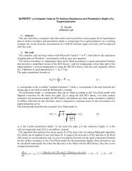
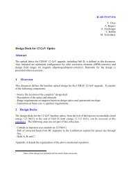
5.2 <strong>Tech</strong>nical ApproachThe <strong>12</strong><strong>GeV</strong> upgrade <strong>Personnel</strong> <strong>Safety</strong> <strong>Systems</strong> (PSS) are built on the technology used in thepresent systems used throughout the <strong>JLab</strong> campus. Programmable Logic Controllers (PLCs)monitor interlock and status indicators on all access control and interlocked equipment.Advances in PLC technology plus the implementation of international standards for the use ofprogrammable systems in safety applications has led to the development of “safety” PLCsdesigned and certified for use in safety systems. A master safety PLC will be installed in themachine Control Center (MCC) building. <strong>Safety</strong> rated (IEC61508) remote I/O will be used inthe Tagger building, Hall D, and the Injector Service Building (Figure 1.)Although in theory the reliability of the safety PLC is such that one <strong>Safety</strong> PLC could beused, i.e. no need for PLC redundancy, the system will be implemented fully redundantly inorder to gain experience with the new technology. The <strong>Safety</strong> PLCs incorporate extensiveself test as well as field wiring diagnostics. All detected unsafe failure modes result in thesystem shutting down hazardous equipment. An undetected unsafe failure of one leg of thesystem will not affect the ability of the second system perform the safety function.
INJHLDNLNAMCCTaggerBuildingHall DW2SLFigure 1 PSS Equipment LocationsSAExisting PSS Rack LocationNew PSS Rack Location
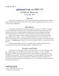
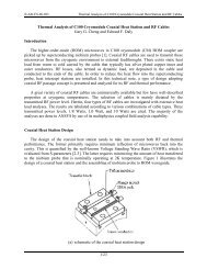
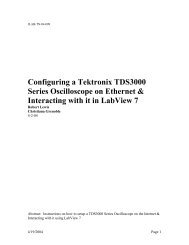
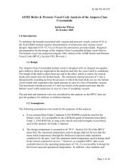
5.2.1 Critical DevicesDevices that isolate an occupied area from a beam operations area are termed “CriticalDevices.” It is <strong>JLab</strong> policy to use at least three critical devices, implemented by at least twodistinct technologies to protect personnel in occupied areas downstream of beam operations.The standard suite of critical devices includes two beam stoppers and control of magnets thatbend the beam in the direction of the downstream target.No device short of a full power 1 MW beam dump is designed to take the full <strong>CEBAF</strong> beampower indefinitely. The beam stoppers are designed such that a beam burn through willrupture an internal nitrogen filled chamber, spoiling the vacuum and dispersing the beamwithin the tunnel. Of course, such drastic measures are only required for the most catastrophicof circumstances. It is therefore necessary to take steps to ensure that beam on the beamstoppers is removed before catastrophic damage to the stopper occurs. <strong>JLab</strong> has solved thisproblem using two approaches.1.) All beamstoppers are protected by a PSS beam current monitoring system. If beamimpinges on the beam stopper the BCM system will shut off the beam in less than 1millisecond.2.) All beam stoppers are protected by a beam diffuser. The beam diffuser is a thincylinder designed to disperse a tightly focused beam in order to spread the beampower over a larger surface area on the stopper face.The existing beam diffuser and the beam current monitor are designed to operate with <strong>12</strong><strong>GeV</strong>beam. No design changes are required. Figure 2 shows a preliminary layout of theTagger/Hall D critical devices.5.2.2 Beam ContainmentIt is critical that beam transport from the entrance of the Hall D vertical bend to the Taggerdump be monitored to ensure that errant beam does not create a radiation area or highradiation area outside of the concrete shielding. It is also vital that beam entering the Taggerarea not transport downstream to Hall D.A new beam transport monitor (Figure 3) will be designed that will measure the DC current inthe upward vertical bend magnets and the Tagger downward vertical bend magnets. The
currents must remain proportional within a given tolerance or a fault will be declared and thePSS will shut down the beam. The BTM will include both warning and trip thresholds.
PSS BeamStoppersPSS Permitto MagnetPowerMagnetPowerSupplyPSS BCMandDiffuserFigure 2 Tagger/Hall D Critical Device Layout
WarnError >WarnThresholdError >TripThresholdTrip-Figure 3. Beam Transport Monitor Functional Diagram
5.2.3 Interdependencies with other systemsThe PSS systems interface with the magnet, RF, and electron gun power supplies. ThePSS provides a “Permit” to operate signal and each device sends an on/off status signalback to the PSS. In the <strong>12</strong><strong>GeV</strong> upgrade, these interfaces remain functionally unchanged.In addition to the interface with power supplies, the Hall D beam line is equipped with abeam diffuser and two beam stoppers. These devices are designed and fabricated by themechanical engineering group to safety system group (SSG) specifications.System Design Responsibility Owner PSS Interface Change frompresent systemsRF High Power Electrical Engineering EES Permit,NoneAmplifier PowerSupplyGroupEmergency OFF,Ready, OFF/SafeMagnet Box PowerSupplyElectrical EngineeringGroupEES Permit, OFF/Safe New supplies will becontrolled through adedicated PSS ACcontactorBeam Stopper MechanicalSSG Permit, Status, NoneEngineering GroupPressureBeam Diffuser MechanicalSSG Permit, Status, NoneEngineering GroupPressureEPICS Software Controls Software SSG Secure Ethernet Drivers forcommunication witha new class of PLCwill be required.Controlled Area Radiation Control Radiation Contact Closure – NoneRadiation MonitoringControl Dose Rate > LimitTable 2 PSS Interfaces
Interfaces with non-PSS equipment will follow the existing system model of usinginterface chassis for isolation. The isolation provides protection against equipmentinduced common mode errors as well as keeps the two PSS chains electrically isolated.