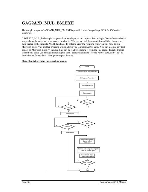
GAG2A2D_MUL_BM.EXEThe sample program GAGEA2D_MUL_BM.EXE is provided with <strong>CompuScope</strong> <strong>SDK</strong> for C/C++ forWindows.GAGEA2D_MUL_BM sample program does a multiple record capture from a single <strong>CompuScope</strong> (dual orsingle channel mode), and bus-masters the data to PC memory. All the records from all the channels arethen written to the separate ASCII data files. In order to view the resulting files, you will have to runMicrosoft Excel or another program, which allows you to import ASCII data. You can also use any texteditor. In Microsoft Excel, the data files can be read by opening it from the File menu. Excel’s ImportWizard will guide you through importing the data. Select “Delimited” for the type of data, and “Tab” asthe delimiter for the data. Then you can plot the data.Flow Chart describing the sample program.StartInitialize Driver and HardwareSet Hardware ParametersAllocate Buffer(s)Start CaptureNTriggeredNTimeoutYForce CaptureYNTimeoutYYBusyNAbort CaptureGroup. Read Trigger,Start and EndaddressesTransfer data using scatter-gatherDMA for optimal speed.Save data to file(s)**Readable by ExcelYMore GroupsNEndPage 46<strong>CompuScope</strong> <strong>SDK</strong> <strong>Manua</strong>l
Description of the Routines used by the sample programFollowing are the routines used by the sample program GAGEA2D_MUL_BM. A brief description for allthe Gage API routines used by each of the following routines is also given. For detailed description of allthe Gage API routines, please see the <strong>CompuScope</strong> API Reference <strong>Manua</strong>l.For a complete description of the SetDefaultBoardLocation, InitBoard, SetBoard, One_SetBoard andboard_settings, refer to their description in the previous section, which describes the GAGEA2D_MS_BMsample program.int CALLBACK WinMain . . . . . . . .This is the main routine in GAGEA2D_MUL_BM.C. In this routine, we first initialize the <strong>CompuScope</strong>driver and hardware and verify the board structure for the <strong>CompuScope</strong> boards.Next, we set the board setting variables by calling the board settings routine. These settings are actuallypassed to the hardware and the <strong>CompuScope</strong> boards are prepared for data capture by the SetBoard routine.We then start the acquisition. As in single record acquisition, the gage_triggered routine is used to detectwhen the first trigger occurs. In multiple record mode, however, gage_busy remains active until the<strong>CompuScope</strong> has captured all multiple records. This occurs when the requested number of records, as setby gage_multiple_record_acquisitions_32, has been acquired for CP500, single PCI or cPCI<strong>CompuScope</strong>s. For older ISA and X12/PCI <strong>CompuScope</strong>s, however, multiple recording terminates andgage_busy becomes inactive only when on-board memory is full.We determine the relevant addresses by calling gage_calculate_mr_addresses for each group. Thegage_calculate_mr_addresses routine returns the addresses for a specific group. If the addresses are read,the return value is the group number that was passed to the routine. In this way, we can loop until all thegroups are read. When this occurs, we know that there are no more groups to be downloaded. Within thisloop we also check if the board supports embedded enhanced trigger bits (EETBs). If the board supportsEETBs, we then call the gage_calculate_mra_addresses routine to adjust the trigger address according tothe EETBs. The gage_calculate_mra_addresses routine is required due to the architecture of thehardware. Depending on the <strong>CompuScope</strong> model, some lower trigger address bits are not stored on the<strong>CompuScope</strong> but must be embedded in the data records, typically in the first sample of each multiplerecord group. Using the gage_calculate_mra_addresses routine, the sample program extracts the EETBsand corrects the trigger address as required.The CP500 <strong>CompuScope</strong>s have the capability of specifying the number of groups to capture rather thanfilling up all of the onboard memory. Each group from the specified channel is saved to an ASCII file inthe current working directory. The raw data from a <strong>CompuScope</strong> board has the most positive voltagerepresented as the least positive value and the least positive voltage represented as the most positive value.To change this for the purposes of plotting the data, we negate the raw values for the 12 bit boards andsubtract them from 255 for 8 bit boards.For example, in dual channel mode the file names are as follows:GAGE_MUL_BM_DUAL_CHANA_GR1.DAT, contains the data of group 1 of channel A.GAGE_MUL_BM_DUAL_CHANB_GR1.DAT, contains the data of group 1 of channel B.GAGE_MUL_BM_DUAL_CHANA_GR2.DAT, contains the data of group 2 of channel A.GAGE_MUL_BM_DUAL_CHANB_GR2.DAT, contains the data of group 2 of channel B.…….In single channel mode the file names are as follows:GAGE_MUL_BM_SINGLE_GR1.DAT, contains the data of group 1.GAGE_MUL_BM_SINGLE_GR2.DAT, contains the data of group 2.GAGE_MUL_BM_SINGLE_GR3.DAT, contains the data of group 3.…….<strong>CompuScope</strong> <strong>SDK</strong> <strong>Manua</strong>l Page 47