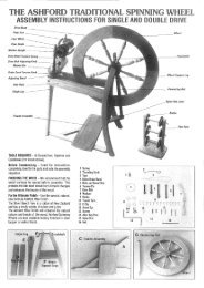
jack loom - Ashford Handicrafts
jack loom - Ashford Handicrafts
jack loom - Ashford Handicrafts
- No tags were found...

Create successful ePaper yourself
Turn your PDF publications into a flip-book with our unique Google optimized e-Paper software.
3ljwkpfnexv
4Jack Loom Hardware ChecklistQUANTITYHARDWAREBag 131442231021Bag 2482156113Bag 31041244122262Bag 4122411TYPE HARDWAREM8 x 50 Eng BoltM8 x 70 Eng BoltM8 x 80 Eng BoltM8 x 90 Eng BoltM8 x 110 Eng BoltM8 x 130 Eng BoltM8 x 55 Cup BoltM8 x 70 Cup Bolt (Eight Shaft: 11)M8 x 75 Cup BoltM8 x 100 Cup Bolt(Eight Shaft: 2 x M8 Dome Nuts)M8 x 25 Washer (Eight Shaft: 85)3/8 x 7/8 Washer8 x 1 ½” Super ScrewM8 Wing Nut3/8” Hex Nut6.30 x 40 Cotter Pin40 x 8 Screw Hook ZincM8 Barrel NutsM8 Nylock NutsM8 Hex Nuts (Eight Shaft: 13)1/8” Starlock Dome Caps (Eight Shaft: 8)Shaft Hooks (Eight Shaft: 8)M8 x 12 mm Brass Spacer12 mm Rubber Buffers6 x 5/8 Pan Head BMA Screws5/8 x 89 mm Steel Rods8 mm x 120 mm Steel Rods (Eight Shaft: 8 mm x 172 mm)¼” x 95 mm Steel Rods600 mm Nylon Braid (Eight Shaft: 40)580 mm 1208 StringHeddle HookReed Hook
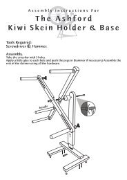
Jack Loom Parts5
6Where numbered parts join
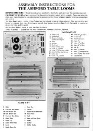
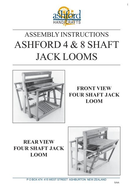
7ASSEMBLY INSTRUCTIONSASHFORD 4 & 8 SHAFTJACK LOOMSTools required:Screwdriver, hammer, ruler, candlewax, light lubrication oil andadjustable spanner.Finishing the wood: The wood your Jack Loom is made of has been lacquered to provide asmooth attractive finish. If desired, use <strong>Ashford</strong> wax polish to enhancethe natural beauty of the wood.Before Assembly:- Read the complete instructions and identify all parts and hardware.- BOLTS. Check and sort the sizes against the full-size drawing onpage 3. Check quantities on page 4.- Rub candlewax or soap on the threads of the woodscrews tomake assembly easier.
8ASSEMBLY OF THE LOOM1 Assemble the base as detailed in illustration 1 and 2 using 90 mm hex head bolts, washers andbarrel nuts. Note the holes in rail BX are to the top. Bushes in parts C and CX are on the inside.
92 Bolt castle side E to the outside of base rail A, and the castle side EX to the base rail AX using70 mm round head bolts, washers and hex nuts as shown in illustration 3. Note the nylon shaftguides are to the inside of the frame and holes for the beater stops face forward.3 Secure the blocks O to the inside of the castle sides E and EX with 70 mm round head bolts,washers and nuts as shown in illustration 3.
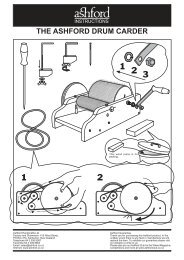
104 Secure one rail M to blocks O using 40 mm screws. Illustration 4. Note the position of the holesfor the steel rods x.5 Place the 6 steel rods x into the rail M.6 FOR FOUR SHAFT LOOMS:Place square wooden spacers onto the two lower rods x followed by a lever assembly N. Placetwo washers onto each lower rod x followed by another lever assembly N. Repeat this procedureuntil all the lever assemblies are in position, finishing with wooden spacers. A drop of light oil on therods will help make treadling easier. See illustration 4a.FOR EIGHT SHAFT LOOMS:Place 5 washers onto the lower rods x followed by a lever assembly N. Place 2 washers onto eachlower rod x followed by another lever assembly N. Repeat this procedure until all the leverassemblies are in position, finishing with 5 washers. A drop of light oil on the rods will help maketreadling easier. See illustration 4a.7 Locate the second rail M onto the steel rods x and secure to blocks O with 40 mm screws.
ILLUSTRATION 4a11
128 Identify the cloth beam supports F (left) and FX (right). FX has a counterbored hole facingthe outside.9 Attach but do not tighten FX to DX with an 80 mm hex bolt, washer and barrel nut and to EX witha 130 mm hex bolt washer and barrel nut as shown in illustration 5. Repeat for the opposite sidewith F, D and E. Keeping the nylon bushes to the inside.for eight shaft <strong>loom</strong>s:A 195 mm threaded shaft, dome nut, washer and barrel nut n are used to connect F and FX to Eand EX.10 Slide the ratchet lever G onto the steel shaft on the cloth beam H and ensure the pawl engages theratchet teeth. See illustration 6.11 Twist the cloth beam support FX slightly and locate the cloth beam H into the nylon bush. Lower Hso the holes in H and F line up and then tap a steel shaft p through the nylon bush and into H. Thentighten the bolts securing F and FX.
13h12 Secure the ratchet lever stop to the insde of the front upright DX with a 40 mm screw. The slopingside of the stop should face inwards at the top to support the lever. When transporting the <strong>loom</strong> pullthe lever sideways past the stop and let it hang down. See illustration 7.13 Attach the ratchet dog h to the right cloth beam support FX as shown in illustration 8 using a 50 mmhex bolt, oversize nut, washer and nyloc nut. The head of the bolt will have to be tapped into thecounterbored hole. The dog should move freely after tightening the nut. See illustration 8.h
1414 treadles four shaft <strong>loom</strong>s:With holes in slots to the bottom, place six treadles J onto the long steel rod with round woodenspacers k between. Place a large hole washer at each end followed by the treadle blocks l. Notethat the rod holes in l must be towards the top. Bolt both blocks l to BX with 70 mm round headbolts, washers and nuts as shown in illustration 9.treadles eight shaft <strong>loom</strong>s:For the eight shaft <strong>loom</strong> an extra support block is bolted to the centre of BX and 5 treadles arelocated either side.15 Tap a 50 mm hex bolt through the inside of castle side EX as shown in illustration 10 and secureto a spacer P with a washer and wingnut. Note the middle slot is closer to the rear of the <strong>loom</strong> andis used to hold the back beam in the closed position.
1516 Attach the hole end of P to the back upright CX with a 55 mm round head bolt, washer andwingnut.17 Remove the wooden spacer P from the castle E to allow the warp roller Z to fit between the uprightswithout twisting them. Then place the warp roller between the back uprights C and CX by locatingthe shaft of the warp roller into the nylon bush in CX. Secure the warp roller by tapping a steel shaftp through the nylon bush in C and into Z. Repeat steps 16 and 17 for the other side.18 Thread two screw hooks into the brake lever W and one screw hook into the hole underneath FXas shown in illustration 12.19 Push a 70 mm hex bolt and washer through the castle side EX. Place a washer, the brake lever W,a washer and then a nyloc nut onto the bolt. Tighten sufficiently with two spanners so the brake levermoves freely. See illustration 11.20 Push the 55 mm round head bolt through the upright CX. Then locate a washer, brass bush, loop ofthe brake cable, washer and hex nut onto the bolt. Now wind the cable around the brake drum andattach the turnbuckle to the screw hook at the end of the brake lever W. See illustration 11.NOTE: When folding the <strong>loom</strong> the turnbuckle MUST be loosened.TURNBUCKLE
1621 Locate the spring between the screw hooks in FX and brake lever W. See illustration 12.NOTE: If the brake does not easily release check the following:A) Adjust the turnbuckle so there is about 30 mm of sideways movement in wire rope.B) That the wire rope is wound evenly on the brake drum and is not crossed over.C) When the brake drum is manufactured and zinc plated, a rough finish can occur which may needto be smoothed off with either a fine file or emery paper.D) A drop of light lubrication oil on the brake drum may assist the brake to function properly.22 Attach the handle f to the crank G with a 100 mm round head bolt by threading the bolt through fand G and locking it with a hex nut. Then locate crank G onto the shaft of warp roller Z and lock inplace with a split pin e. Spread the ends of the pin to prevent it falling out. See illustration 12.NOTE: The cloth and warp roller must rotate in the direction shown. See illustration 12a.fIllustration 12a
1723 assembly of the shaftsYour <strong>Ashford</strong> Jack Loom has been supplied with Texsolv Heddles.Each bundle contains 100 heddles which enable you to use 200 pershaft on a four shaft <strong>loom</strong> and 100 per shaft on an eight shaft <strong>loom</strong>.To load the heddles:Take a bundle of heddles (DO NOT REMOVE THE PINK TIES)Thread the flat steel bars (see note at bottom of page if you have a800mm <strong>loom</strong>) through the bundle top and bottom as illustrated inillustration 14b. Then carefully spring the steel bars into the slots inthe shafts taking care not to bend the bars.THEN remove the ties and spread the heddles. Extra Texsolv heddlesfor finer threadings may be obtained from your <strong>Ashford</strong> dealer.The heddles can be used connectedor cut. (Use sharp scissors.) Cuttingis best when the heddles are hangingon the harness.PLEASE NOTE:If your <strong>loom</strong> is an 800mm <strong>loom</strong>, the steel bars areround and please omit step 24 and go straight tostep 25.
1824 Each shaft one hole on either side. Fit one hook v into one side of each shaft. Secure by pressing adome cap w onto the hook. It may be easier to do this when the hook v is sitting across the cornerof a table. Spread the heddles evenly either side of the hook and then clip the stainless steel barover the hook. The hooks prevent the bars from sagging when being raised. See illustrations13, 13 A and 14.25 Rub candlewax on the ends of the shafts before loading them into the nylon guides. Load the shaftsand locate the <strong>jack</strong> pin into the hole in the shaft. If any of the shafts are curved, load them so that thecurves are all in the same direction. Load the harnesses so that if any are bent, to avoid them rubbingon each other put the bends all in the same direction
26 Attach the castle top rails T to the castle sides E and EX with 40 mm screws. Locate the shelf Vonto the castle. It is easily removable for access to the shafts. See illustration 15.27 Locate the front and back beams Y onto the tenons of uprights C, CX and D, DX. The beams areeasily removable to allow access to the shafts when warping.28 Tap the beater stops j into the castle sides E and EX. Note the lead holes for the screws face out.Then attach the rubber buffers to the stops with 16 mm screws.29 Assemble the beater by joining the sides Q to the bottom rail R with 80 mm hex head bolts, washersand barrel nuts n. Note the shuttle race faces forward. See illustration 16.30 Place the reed into the groove in the bottom rail R. Secure the top beater rail S to the sides with75 mm round head bolts, washers and wing nuts.19
20j31 Place the beater in position on the <strong>loom</strong> frame and push a 110 mm hex bolt and washer through theside Q, the front hole in the spacer blocks attached to the sides A and AX and secure with washerand nyloc nut. The two holes in the spacer blocks allow the beater to be moved forwards orbackwards to suit the weaving. See illustration 17. Do not tighten bolts. Beater must movebackwards and forwards freely.
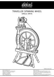
2132 Flame the ends of the nylon cords to prevent fraying. Then tie a knot in the cords and connect thetreadles J to the parallel lams. See illustration 18.NOTE: There are four parallel lams and four slots in each treadle on the four shaft <strong>loom</strong>, and eightlams and eight slots in each treadle on the eight shaft <strong>loom</strong>. After determining the pattern required,connect the cord from each lam to the slot in the treadle directly beneath it. The knots in the cordslocate into the holes in the underside of the treadles.Illustration 19 is one of many alternative tie ups for the four shaft <strong>loom</strong> with treadles one and sixfor tabby weave.
22tie up for 8 shaft <strong>jack</strong> <strong>loom</strong>
2333 Attach the raddle blocks to the castle sides E and EX with 40 mm screws. Then locate the raddlepins into these blocks and sit the raddle in position. See illustration 20.34 Slide the round apron sticks into the pockets sewn into the end of the cloth aprons. Tie the roundwarp sticks parallel to the apron sticks with the cut pieces of string as shown in illustration 21.The <strong>loom</strong> is now ready to be warped. Refer to theLEARN TO WEAVE booklet for more information.