ICS-1000 Ion Chromatography System Operator's Manual
ICS-1000 Ion Chromatography System Operator's Manual
ICS-1000 Ion Chromatography System Operator's Manual
- No tags were found...

Create successful ePaper yourself
Turn your PDF publications into a flip-book with our unique Google optimized e-Paper software.
<strong>ICS</strong>-<strong>1000</strong> ION CHROMATOGRAPHY SYSTEMOPERATOR’S MANUAL© 2003 Dionex CorporationDocument No. 031879Revision 01March 2003
©2003 by Dionex CorporationAll rights reserved worldwide.Printed in the United States of America.This publication is protected by federal copyright law. No part of this publicationmay be copied or distributed, transmitted, transcribed, stored in a retrieval system, ortransmitted into any human or computer language, in any form or by any means,electronic, mechanical, magnetic, manual, or otherwise, or disclosed to third partieswithout the express written permission of Dionex Corporation, 1228 Titan Way,Sunnyvale, California 94088-3603 U.S.A.DISCLAIMER OF WARRANTY AND LIMITED WARRANTYTHIS PUBLICATION IS PROVIDED “AS IS” WITHOUT WARRANTY OFANY KIND. DIONEX CORPORATION DOES NOT WARRANT,GUARANTEE, OR MAKE ANY EXPRESS OR IMPLIEDREPRESENTATIONS REGARDING THE USE, OR THE RESULTS OF THEUSE, OF THIS PUBLICATION IN TERMS OF CORRECTNESS, ACCURACY,RELIABILITY, CURRENTNESS, OR OTHERWISE. FURTHER, DIONEXCORPORATION RESERVES THE RIGHT TO REVISE THIS PUBLICATIONAND TO MAKE CHANGES FROM TIME TO TIME IN THE CONTENTHEREINOF WITHOUT OBLIGATION OF DIONEX CORPORATION TONOTIFY ANY PERSON OR ORGANIZATION OF SUCH REVISION ORCHANGES.TRADEMARKSMMS MicroMembrane Suppressor is a trademark of Dionex Corporation.AES® Atlas Electrolytic Suppressor, Chromeleon®, OnGuard®, and SRS® Self-Regenerating Suppressor are registered trademarks of Dionex Corporation.Teflon® is a registered trademark of E.I. duPont de Nemours & Co.Windows® is a registered trademark of Microsoft Corporation.PRINTING HISTORYRevision 01, March 2003
Contents1 • Introduction1.1 Introduction to <strong>Ion</strong> <strong>Chromatography</strong> (IC) . . . . . . . . . . . . . . . . . . . . . . .1-11.2 Overview of the <strong>ICS</strong>-<strong>1000</strong> . . . . . . . . . . . . . . . . . . . . . . . . . . . . . . . . . . .1-41.3 About This <strong>Manual</strong> . . . . . . . . . . . . . . . . . . . . . . . . . . . . . . . . . . . . . . . .1-51.3.1 Safety Messages and Notes . . . . . . . . . . . . . . . . . . . . . . . . . . .1-61.3.2 Safety Labels . . . . . . . . . . . . . . . . . . . . . . . . . . . . . . . . . . . . . .1-82 • Features2.1 Operating Features . . . . . . . . . . . . . . . . . . . . . . . . . . . . . . . . . . . . . . . . .2-12.1.1 Front Panel . . . . . . . . . . . . . . . . . . . . . . . . . . . . . . . . . . . . . . . .2-12.1.2 Top Cover . . . . . . . . . . . . . . . . . . . . . . . . . . . . . . . . . . . . . . . . .2-32.1.3 Component Panel . . . . . . . . . . . . . . . . . . . . . . . . . . . . . . . . . . .2-42.1.4 Rear Panel . . . . . . . . . . . . . . . . . . . . . . . . . . . . . . . . . . . . . . . . .2-72.2 Flow Schematic . . . . . . . . . . . . . . . . . . . . . . . . . . . . . . . . . . . . . . . . . . .2-92.3 The Chromeleon Interface . . . . . . . . . . . . . . . . . . . . . . . . . . . . . . . . . .2-112.3.1 The Chromeleon Main Window and Browser . . . . . . . . . . . .2-122.3.2 The <strong>ICS</strong>-<strong>1000</strong> Control Panels . . . . . . . . . . . . . . . . . . . . . . . . .2-132.4 <strong>System</strong> Component Details . . . . . . . . . . . . . . . . . . . . . . . . . . . . . . . . .2-192.4.1 Vacuum Degas Assembly (Optional) . . . . . . . . . . . . . . . . . .2-192.4.2 Eluent Valve . . . . . . . . . . . . . . . . . . . . . . . . . . . . . . . . . . . . . .2-212.4.3 Pump . . . . . . . . . . . . . . . . . . . . . . . . . . . . . . . . . . . . . . . . . . . .2-21Doc. 031879-01 3/03i
<strong>ICS</strong>-<strong>1000</strong> <strong>Ion</strong> <strong>Chromatography</strong> <strong>System</strong>2.4.4 Injection Valve . . . . . . . . . . . . . . . . . . . . . . . . . . . . . . . . . . . 2-242.4.5 Column Heater (Optional) . . . . . . . . . . . . . . . . . . . . . . . . . . . 2-262.4.6 Suppressor . . . . . . . . . . . . . . . . . . . . . . . . . . . . . . . . . . . . . . . 2-272.4.7 DS6 Heated Conductivity Cell . . . . . . . . . . . . . . . . . . . . . . . 2-273 • Operation and Maintenance3.1 Operation Overview . . . . . . . . . . . . . . . . . . . . . . . . . . . . . . . . . . . . . . . 3-13.2 Power Up the <strong>System</strong> . . . . . . . . . . . . . . . . . . . . . . . . . . . . . . . . . . . . . . 3-33.3 Start Chromeleon . . . . . . . . . . . . . . . . . . . . . . . . . . . . . . . . . . . . . . . . . 3-43.4 Set Up the Eluent Reservoir . . . . . . . . . . . . . . . . . . . . . . . . . . . . . . . . . 3-63.4.1 Prepare the Eluent . . . . . . . . . . . . . . . . . . . . . . . . . . . . . . . . . . 3-63.4.2 Degas the Eluent . . . . . . . . . . . . . . . . . . . . . . . . . . . . . . . . . . . 3-63.4.3 Filter the Eluent . . . . . . . . . . . . . . . . . . . . . . . . . . . . . . . . . . . . 3-73.4.4 Fill the Reservoir . . . . . . . . . . . . . . . . . . . . . . . . . . . . . . . . . . . 3-83.4.5 Set the Eluent Level . . . . . . . . . . . . . . . . . . . . . . . . . . . . . . . . . 3-83.4.6 Connect the Reservoir . . . . . . . . . . . . . . . . . . . . . . . . . . . . . . . 3-83.5 Check All Connections . . . . . . . . . . . . . . . . . . . . . . . . . . . . . . . . . . . . . 3-93.6 Prime the Pump . . . . . . . . . . . . . . . . . . . . . . . . . . . . . . . . . . . . . . . . . . 3-93.7 Set <strong>System</strong> Operating Conditions . . . . . . . . . . . . . . . . . . . . . . . . . . . . 3-103.8 Equilibrate the <strong>System</strong> and Verify Operational Status . . . . . . . . . . . 3-113.9 Prepare Samples . . . . . . . . . . . . . . . . . . . . . . . . . . . . . . . . . . . . . . . . . 3-123.9.1 Collecting and Storing Samples . . . . . . . . . . . . . . . . . . . . . . 3-123.9.2 Pretreating Samples . . . . . . . . . . . . . . . . . . . . . . . . . . . . . . . . 3-123.9.3 Diluting Samples . . . . . . . . . . . . . . . . . . . . . . . . . . . . . . . . . . 3-13ii Doc. 031879-01 3/03
<strong>ICS</strong>-<strong>1000</strong> <strong>Ion</strong> <strong>Chromatography</strong> <strong>System</strong>4.13 Baseline Noise or Drift . . . . . . . . . . . . . . . . . . . . . . . . . . . . . . . . . . . . 4-194.14 Vacuum Degas Assembly Does Not Run . . . . . . . . . . . . . . . . . . . . . . 4-205 • Service5.1 Diagnostic and Calibration Procedures . . . . . . . . . . . . . . . . . . . . . . . . 5-15.1.1 Chromeleon Wellness Panel Overview . . . . . . . . . . . . . . . . . . 5-25.1.2 Calibrating the Conductivity Cell . . . . . . . . . . . . . . . . . . . . . . 5-45.1.3 Calibrating the Flow Rate . . . . . . . . . . . . . . . . . . . . . . . . . . . . 5-65.1.4 Calibrating the Vacuum Degas Assembly . . . . . . . . . . . . . . . . 5-75.2 Isolating a Restriction in the Liquid Lines . . . . . . . . . . . . . . . . . . . . . . 5-75.3 Replacing Tubing and Fittings . . . . . . . . . . . . . . . . . . . . . . . . . . . . . . . 5-95.4 Rebuilding the Injection Valve . . . . . . . . . . . . . . . . . . . . . . . . . . . . . . 5-105.5 Cleaning and Replacing the Pump Check Valves . . . . . . . . . . . . . . . 5-115.6 Replacing a Pump Piston Seal and Piston Rinse Seal . . . . . . . . . . . . 5-135.7 Replacing a Pump Piston . . . . . . . . . . . . . . . . . . . . . . . . . . . . . . . . . . 5-175.8 Replacing the Waste Valve or Priming Valve O-Ring . . . . . . . . . . . . 5-185.9 Replacing the Conductivity Cell . . . . . . . . . . . . . . . . . . . . . . . . . . . . . 5-205.10 Replacing the Suppressor . . . . . . . . . . . . . . . . . . . . . . . . . . . . . . . . . . 5-225.11 Replacing the Column Heater . . . . . . . . . . . . . . . . . . . . . . . . . . . . . . . 5-235.12 Replacing the Column Heater Heat Exchanger . . . . . . . . . . . . . . . . . 5-255.13 Replacing the Eluent Valve . . . . . . . . . . . . . . . . . . . . . . . . . . . . . . . . 5-265.14 Replacing the Leak Sensor . . . . . . . . . . . . . . . . . . . . . . . . . . . . . . . . . 5-285.15 Priming with Isopropyl Alcohol . . . . . . . . . . . . . . . . . . . . . . . . . . . . . 5-295.16 Changing Main Power Fuses . . . . . . . . . . . . . . . . . . . . . . . . . . . . . . . 5-30iv Doc. 031879-01 3/03
ContentsA • SpecificationsA.1 Electrical . . . . . . . . . . . . . . . . . . . . . . . . . . . . . . . . . . . . . . . . . . . . . . . A-1A.2 Physical . . . . . . . . . . . . . . . . . . . . . . . . . . . . . . . . . . . . . . . . . . . . . . . . A-1A.3 Environmental . . . . . . . . . . . . . . . . . . . . . . . . . . . . . . . . . . . . . . . . . . . A-1A.4 Front Panel . . . . . . . . . . . . . . . . . . . . . . . . . . . . . . . . . . . . . . . . . . . . . . A-2A.5 Pump . . . . . . . . . . . . . . . . . . . . . . . . . . . . . . . . . . . . . . . . . . . . . . . . . . A-2A.6 Detector . . . . . . . . . . . . . . . . . . . . . . . . . . . . . . . . . . . . . . . . . . . . . . . . A-3A.7 Conductivity Cell with Heat Exchanger . . . . . . . . . . . . . . . . . . . . . . . A-3A.8 Injection Valve . . . . . . . . . . . . . . . . . . . . . . . . . . . . . . . . . . . . . . . . . . A-3A.9 Vacuum Degas Assembly (Optional) . . . . . . . . . . . . . . . . . . . . . . . . . A-3A.10 Column Heater (Optional) . . . . . . . . . . . . . . . . . . . . . . . . . . . . . . . . . . A-4B • InstallationB.1 Facility Requirements . . . . . . . . . . . . . . . . . . . . . . . . . . . . . . . . . . . . . B-1B.2 Unpacking the <strong>ICS</strong>-<strong>1000</strong> <strong>System</strong> . . . . . . . . . . . . . . . . . . . . . . . . . . . . B-2B.2.1 Unpacking the Computer (North America only). . . . . . . . . . . B-4B.2.2 Unpacking the Computer (outside North America) . . . . . . . . B-4B.3 Installing Chromeleon . . . . . . . . . . . . . . . . . . . . . . . . . . . . . . . . . . . . . B-5B.4 Installing the Chromeleon Software License . . . . . . . . . . . . . . . . . . . B-6B.5 Connecting the <strong>ICS</strong>-<strong>1000</strong> to the Chromeleon PC . . . . . . . . . . . . . . . . B-9B.5.1 Connecting the <strong>ICS</strong>-<strong>1000</strong> to the PC . . . . . . . . . . . . . . . . . . . . B-9B.5.2 Connecting Additional USB Devices . . . . . . . . . . . . . . . . . . B-10B.6 Connecting the Power Cord . . . . . . . . . . . . . . . . . . . . . . . . . . . . . . . . B-11B.7 Turning On the <strong>ICS</strong>-<strong>1000</strong> Power . . . . . . . . . . . . . . . . . . . . . . . . . . . . B-12Doc. 031879-01 3/03v
<strong>ICS</strong>-<strong>1000</strong> <strong>Ion</strong> <strong>Chromatography</strong> <strong>System</strong>B.8 Setting Up Chromeleon . . . . . . . . . . . . . . . . . . . . . . . . . . . . . . . . . . .B-13B.8.1 Assigning the <strong>ICS</strong>-<strong>1000</strong> to a Timebase . . . . . . . . . . . . . . . . .B-13B.8.2 Assigning DX-LAN Devices to the Timebase (Optional) . . .B-16B.9 Installing and Plumbing the Columns and Suppressor . . . . . . . . . . . .B-19B.9.1 Column Heater Setup (Optional) . . . . . . . . . . . . . . . . . . . . . .B-19B.9.2 Installing the Columns . . . . . . . . . . . . . . . . . . . . . . . . . . . . . .B-20B.9.3 Installing the Suppressor . . . . . . . . . . . . . . . . . . . . . . . . . . . .B-21B.10 Connecting the Waste Lines . . . . . . . . . . . . . . . . . . . . . . . . . . . . . . . .B-23B.10.1 Installing the Gas Separator Waste Tube . . . . . . . . . . . . . . . .B-23B.11 Setting Up the Eluent Reservoir . . . . . . . . . . . . . . . . . . . . . . . . . . . . .B-25B.12 Setting Up a Chromeleon Application . . . . . . . . . . . . . . . . . . . . . . . .B-26B.12.1 Verifying Chromeleon Communication. . . . . . . . . . . . . . . . .B-35B.13 Setting the Eluent Level . . . . . . . . . . . . . . . . . . . . . . . . . . . . . . . . . . .B-35B.14 Priming the Pump . . . . . . . . . . . . . . . . . . . . . . . . . . . . . . . . . . . . . . . .B-36B.14.1 Priming the Eluent Lines with a Syringe . . . . . . . . . . . . . . . .B-36B.14.2 Priming with the Prime Button. . . . . . . . . . . . . . . . . . . . . . . .B-38B.15 Equilibrating the <strong>System</strong> . . . . . . . . . . . . . . . . . . . . . . . . . . . . . . . . . .B-39B.16 Verifying Operational Status . . . . . . . . . . . . . . . . . . . . . . . . . . . . . . .B-39B.17 Connecting an AS50 Autosampler (Optional) . . . . . . . . . . . . . . . . . .B-40B.17.1 AS50 Configuration Requirements . . . . . . . . . . . . . . . . . . . .B-40B.17.2 AS50 Connections . . . . . . . . . . . . . . . . . . . . . . . . . . . . . . . . .B-41B.17.3 Enable AS50 Control of the Injection Valve . . . . . . . . . . . . .B-43B.18 Connecting an AS40 Automated Sampler (Optional) . . . . . . . . . . . .B-44B.19 Analog Output Connection (Optional) . . . . . . . . . . . . . . . . . . . . . . . .B-46B.20 Pressurizing the Eluent Reservoir (Optional) . . . . . . . . . . . . . . . . . . .B-46vi Doc. 031879-01 3/03
ContentsB.20.1 Connecting the Gas Source (Optional) . . . . . . . . . . . . . . . . . B-47B.20.2 Pressurizing the Eluent Reservoir (Optional) . . . . . . . . . . . . B-48B.21 Pump Continuous Seal Wash Connections (Optional) . . . . . . . . . . . B-49B.22 <strong>Manual</strong>ly Connecting to a Control Panel . . . . . . . . . . . . . . . . . . . . . B-51B.23 Installation Troubleshooting . . . . . . . . . . . . . . . . . . . . . . . . . . . . . . . B-53C • TTL and Relay ControlC.1 TTL and Relay Connections . . . . . . . . . . . . . . . . . . . . . . . . . . . . . . . . C-1C.1.1 Selecting TTL Input Functions and Control Types. . . . . . . . . C-3C.2 Controlling TTL and Relay Outputs . . . . . . . . . . . . . . . . . . . . . . . . . . C-5C.3 Example Setup for Stand-Alone Operation . . . . . . . . . . . . . . . . . . . . . C-7D • Reordering InformationE • FAQE.1 How do I hook up an autosampler? . . . . . . . . . . . . . . . . . . . . . . . . . . . E-1E.2 How do I print? . . . . . . . . . . . . . . . . . . . . . . . . . . . . . . . . . . . . . . . . . . E-1E.3 Why are the retention times moving? . . . . . . . . . . . . . . . . . . . . . . . . . E-1E.4 How do I adjust retention times? . . . . . . . . . . . . . . . . . . . . . . . . . . . . . E-1E.5 When should I remake standards? . . . . . . . . . . . . . . . . . . . . . . . . . . . . E-2E.6 When should I remake eluents? . . . . . . . . . . . . . . . . . . . . . . . . . . . . . . E-2E.7 How do I start Chromeleon? . . . . . . . . . . . . . . . . . . . . . . . . . . . . . . . . E-2E.8 How do I delete data? . . . . . . . . . . . . . . . . . . . . . . . . . . . . . . . . . . . . . E-2E.9 How do I back up data? . . . . . . . . . . . . . . . . . . . . . . . . . . . . . . . . . . . . E-2Doc. 031879-01 3/03vii
<strong>ICS</strong>-<strong>1000</strong> <strong>Ion</strong> <strong>Chromatography</strong> <strong>System</strong>E.10 How do I shut off the system? . . . . . . . . . . . . . . . . . . . . . . . . . . . . . . . E-2E.11 How do I store columns? . . . . . . . . . . . . . . . . . . . . . . . . . . . . . . . . . . . E-2E.12 How do I know when a column is dirty? . . . . . . . . . . . . . . . . . . . . . . . E-3E.13 How do I clean a column? . . . . . . . . . . . . . . . . . . . . . . . . . . . . . . . . . . E-3E.14 Why is the conductivity high? . . . . . . . . . . . . . . . . . . . . . . . . . . . . . . . E-3F • Glossaryviii Doc. 031879-01 3/03
1 • Introduction1.1 Introduction to <strong>Ion</strong> <strong>Chromatography</strong> (IC)The Dionex <strong>ICS</strong>-<strong>1000</strong> <strong>Ion</strong> <strong>Chromatography</strong> <strong>System</strong> (<strong>ICS</strong>-<strong>1000</strong>) performs ionanalyses using suppressed or non-suppressed conductivity detection. An ionchromatography system typically consists of a liquid eluent, a high-pressurepump, a sample injector, a guard and separator column, a chemical suppressor, aconductivity cell, and a data collection system.Before running a sample, the ion chromatography system is calibrated using astandard solution. By comparing the data obtained from a sample to that obtainedfrom the known standard, sample ions can be identified and quantitated. The datacollection system, typically a computer running chromatography software,produces a chromatogram (a plot of the detector output vs. time). Thechromatography software converts each peak in the chromatogram to a sampleconcentration and produces a printout of the results.Doc. 031879-01 3/03 1-1
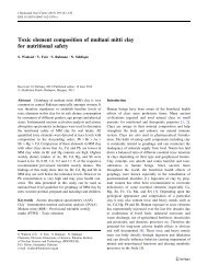
<strong>ICS</strong>-<strong>1000</strong> <strong>Ion</strong> <strong>Chromatography</strong> <strong>System</strong>A typical IC analysis consists of 6 stages (see Figure 1-1).6. Data AnalysisConductivityCell5. DetectionSuppressor1. EluentDeliveryEluentPumpSeparatorColumnGuard Column4. Suppression3. SeparationInjectionValve2. SampleInjectionSample LoopSampleFigure 1-1. <strong>Ion</strong> Analysis Process1. Eluent Delivery• Eluent, a liquid that helps to separate the sample ions, carries thesample through the ion chromatography system. The <strong>ICS</strong>-<strong>1000</strong> is anisocratic delivery system. This means that the eluent composition andconcentration remain constant throughout the run.2. Sample Injection• The liquid sample is loaded into a sample loop either manually orautomatically (if an automated sampler is installed). When triggered,the <strong>ICS</strong>-<strong>1000</strong> injects the sample into the eluent stream.• The pump pushes the eluent and sample through the guard andseparator columns (chemically-inert tubes packed with a polymericresin). The guard column removes contaminants that might poison theseparator column.1-2 Doc. 031879-01 3/03
1 • Introduction3. Separation• As the eluent and sample are pumped through the separator column,the sample ions are separated. In the <strong>ICS</strong>-<strong>1000</strong>, the mode ofseparation is called ion exchange. This is based on the premise thatdifferent sample ions migrate through the IC column at different rates,depending upon their interactions with the ion exchange sites.4. Suppression• After the eluent and sample ions leave the column, they flow througha suppressor that selectively enhances detection of the sample ionswhile suppressing the conductivity of the eluent.5. Detection• A conductivity cell measures the electrical conductance of the sampleions as they emerge from the suppressor and produces a signal basedon a chemical or physical property of the analyte.6. Data Analysis• The conductivity cell transmits the signal to a data collection system.• The data collection system (for the <strong>ICS</strong>-<strong>1000</strong>, this is Chromeleon®)identifies the ions based on retention time, and quantifies each analyteby integrating the peak area or peak height. The data is quantitated bycomparing the sample peaks in a chromatogram to those producedfrom a standard solution. The results are displayed as a chromatogramand the concentrations of ionic analytes can be automaticallydetermined and tabulated.Doc. 031879-01 3/03 1-3
<strong>ICS</strong>-<strong>1000</strong> <strong>Ion</strong> <strong>Chromatography</strong> <strong>System</strong>1.2 Overview of the <strong>ICS</strong>-<strong>1000</strong>The <strong>ICS</strong>-<strong>1000</strong> is an integrated ion chromatography system containing a pump,injection valve, column heater, and conductivity detector. Other systemcomponents, including a guard column, separator column, and suppressor vary,depending on the analyses to be performed.The <strong>ICS</strong>-<strong>1000</strong> can optionally be configured with a column heater for temperaturecontrol of the column.<strong>ICS</strong>-<strong>1000</strong> operation is controlled remotely by a personal computer runningWindows® 2000 or Windows XP and Chromeleon software (version 6.5 SP2 orlater). Chromeleon also provides data acquisition and data processing functions.For communication between the <strong>ICS</strong>-<strong>1000</strong> and Chromeleon, the <strong>ICS</strong>-<strong>1000</strong> isconnected to a USB (Universal Serial Bus) port on the computer or a USB hub.For installation instructions, see Section B.5 and also refer to Installing theChromeleon IC <strong>System</strong> (Document No. 031883).1-4 Doc. 031879-01 3/03
1 • Introduction1.3 About This <strong>Manual</strong>Chapter 1IntroductionChapter 2FeaturesOverviewChapter 3Operation andMaintenanceChapter 4TroubleshootingChapter 5ServiceAppendix ASpecificationsAppendix BInstallationAppendix CTTL and RelayControlAppendix DReorderingInformationAppendix EFAQAppendix FGlossaryIntroduces ion analysis and the <strong>ICS</strong>-<strong>1000</strong>; explains theconventions used in this manual, including safety-relatedinformation.Provides an overview of <strong>ICS</strong>-<strong>1000</strong> operating features andsystem components; introduces the Chromeleon userinterface.Provides operating instructions and describes routinepreventive maintenance procedures.Lists problems and presents step-by-step procedures forhow to isolate and eliminate the cause of each problem.Provides step-by-step instructions for routine service andparts replacement procedures that the user can perform.Lists the <strong>ICS</strong>-<strong>1000</strong> specifications and installation siterequirements.Describes how to install the <strong>ICS</strong>-<strong>1000</strong>.Describes the <strong>ICS</strong>-<strong>1000</strong> TTL and relay control features.Lists spare parts for the <strong>ICS</strong>-<strong>1000</strong>.Provides answers to frequently asked questions about<strong>ICS</strong>-<strong>1000</strong> operation.Defines terms commonly used in ion analysis.Doc. 031879-01 3/03 1-5
<strong>ICS</strong>-<strong>1000</strong> <strong>Ion</strong> <strong>Chromatography</strong> <strong>System</strong>1.3.1 Safety Messages and NotesThis manual contains warnings and precautionary statements that canprevent personal injury and/or damage to the <strong>ICS</strong>-<strong>1000</strong> when properlyfollowed. Safety messages appear in bold type and are accompanied byicons, as shown below.Indicates an imminently hazardous situation which, if not avoided, willresult in death or serious injury.Indicates a potentially hazardous situation which, if not avoided,could result in death or serious injury.Indicates a potentially hazardous situation which, if not avoided, mayresult in minor or moderate injury. Also used to identify a situation orpractice that may seriously damage the instrument, but will not causeinjury.Indicates that the function or process of the instrument may beimpaired. Operation does not constitute a hazard.Messages d'avertissement en françaisSignale une situation de danger immédiat qui, si elle n'est pas évitée,entraînera des blessures graves à mortelles.Signale une situation de danger potentiel qui, si elle n'est pas évitée,pourrait entraîner des blessures graves à mortelles.Signale une situation de danger potentiel qui, si elle n'est pas évitée,pourrait entraîner des blessures mineures à modérées. Égalementutilisé pour signaler une situation ou une pratique qui pourraitgravement endommager l'instrument mais qui n'entraînera pas deblessures.1-6 Doc. 031879-01 3/03
1 • IntroductionWarnhinweise in DeutschBedeutet unmittelbare Gefahr. Mißachtung kann zum Tod oderschwerwiegenden Verletzungen führen.Bedeutet eine mögliche Gefährdung. Mißachtung kann zum Tod oderschwerwiegenden Verletzungen führen.Bedeutet eine mögliche Gefährdung. Mißachtung kann zu kleinerenoder mittelschweren Verletzungen führen. Wird auch verwendet, wenneine Situation zu schweren Schäden am Gerät führen kann, jedochkeine Verletzungsgefahr besteht.NotesInformational messages also appear throughout this manual. These arelabeled NOTE and are in bold type:NOTENOTES call attention to certain information. They alertyou to an unexpected result of an action, suggest how tooptimize instrument performance, etc.Doc. 031879-01 3/03 1-7
<strong>ICS</strong>-<strong>1000</strong> <strong>Ion</strong> <strong>Chromatography</strong> <strong>System</strong>1.3.2 Safety LabelsThe <strong>ICS</strong>-<strong>1000</strong> meets EN 61010-1:1993 (safety), CAN/CSA-C22.2 No.1010.1-92 (safety), UL 3101-1/10.93 (safety), EN 50082-1:1992(susceptibility), EN 55011:1991 (emissions). The TUV GS, C, US Marksafety labels and the CE Mark label on the <strong>ICS</strong>-<strong>1000</strong> attest to compliancewith these standards.The symbols below appear on the <strong>ICS</strong>-<strong>1000</strong> or on <strong>ICS</strong>-<strong>1000</strong> labels.Alternating currentProtective conductor terminal (earth ground)Power supply is onPower supply is off1-8 Doc. 031879-01 3/03
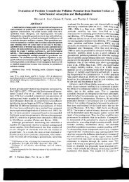
2•FeaturesThis chapter describes key <strong>ICS</strong>-<strong>1000</strong> features and introduces the Chromeleon userinterface.2.1 Operating Features2.1.1 Front PanelFigure 2-1 illustrates the front panel of the <strong>ICS</strong>-<strong>1000</strong>.PowerLEDStatusLEDsInjectionPortInjection PortThe sample to be analyzed canbe injected manually into theinjection port, using a syringe.For automated sampleinjection, the <strong>ICS</strong>-<strong>1000</strong> must beconnected to an autosampler.For more information aboutsample injection, seeSection 3.10.LEDsThe status LEDs (seeFigure 2-2) indicate the statusof various system functions.See Table 2-1for a descriptionof each LEDs function. Thepower LED indicates whetherthe <strong>ICS</strong>-<strong>1000</strong> power is on.Figure 2-1. <strong>ICS</strong>-<strong>1000</strong> Front PanelDoc. 031879-01 3/03 2-1
<strong>ICS</strong>-<strong>1000</strong> <strong>Ion</strong> <strong>Chromatography</strong> <strong>System</strong>INJECT VALVESTATUSLoadModule ConnectedInjectAcquiring DataPumpALARMSuppressorColumn HeaterFigure 2-2. Status LEDsLED Label If On (Green) If FlashingLoadInjectInjection valve is in Loadposition.Injection valve is in Injectposition.Valve error.Valve error.Alarm No “on” (green) state. Error detected. Check the ChromeleonAudit Trail for the cause.ModuleConnectedAcquiringData<strong>ICS</strong>-<strong>1000</strong> is connected toa Chromeleon timebase.Sequence or manual dataacquisition is in progress.Does not flash.Sequence has stopped due to an error.Pump Pump is on. High or low pressure limit is exceeded.The pump is turned offSuppressorColumnHeaterSuppressor is on andcurrent is being applied toit.Column heater is at settemperature.Table 2-1. <strong>ICS</strong>-<strong>1000</strong> Status LED StatesContinuity check failed or suppressor isover the voltage, current, or power limit.The suppressor is turned offColumn heater is transitioning to a newtemperature.2-2 Doc. 031879-01 3/03
2 • Features2.1.2 Top CoverFigure 2-3 illustrates the top cover of the <strong>ICS</strong>-<strong>1000</strong>.Reservoir StorageThe <strong>ICS</strong>-<strong>1000</strong> top cover has roomfor up to three 2-L plasticreservoirs (P/N 044129).Tubing ChaseThe tubing chase under the topcover routes tubing to the front ofthe <strong>ICS</strong>-<strong>1000</strong>.Figure 2-3. <strong>ICS</strong>-<strong>1000</strong> (Top View)Doc. 031879-01 3/03 2-3
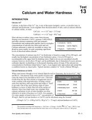
<strong>ICS</strong>-<strong>1000</strong> <strong>Ion</strong> <strong>Chromatography</strong> <strong>System</strong>2.1.3 Component PanelFigure 2-4 shows the user-accessible components installed on thecomponent panel behind the <strong>ICS</strong>-<strong>1000</strong> front door.11101Eluent Valve2Leak Sensor83Pump Heads974Pressure Transducer5Injection Valve6Columns54678Connector foroptional columnheaterSuppressor1113291011DS6 ConductivityCellMounting bracketsfor a secondsuppressorTubing Chase (2)Figure 2-4. <strong>ICS</strong>-<strong>1000</strong> Component Panel2-4 Doc. 031879-01 3/03
2 • FeaturesEluent ValveThe eluent valve controls the flow from the eluent reservoir. It opensautomatically when the pump is running and closes when the pump is off.Leak SensorThe leak sensor is installed in the drip tray at the bottom of the componentpanel. If liquid accumulates in the tray, an error message is reported inChromeleon and the Alarm LED flashes.Pump HeadsThe <strong>ICS</strong>-<strong>1000</strong> includes a serial isocratic dual-head pump. The flow ratecan be set to 0.00 and to between 0.05 and 5.0 mL/min. However, foroptimum performance, set the flow rate to between 0.4 and 2.0 mL/min.Setting the flow rate to 0.00 turns off the pump. See Section 2.4.3 fordetails about the pump.Pressure TransducerThe pressure transducer measures the system backpressure.Injection ValveThe injection valve is a six-port, electrically-activated valve. A 25-µLsample loop (P/N 042857) is installed on the valve at the factory. SeeSection 2.4.4 for details about valve operation.Separator and Guard ColumnsBoth the separator and guard columns are packed with resin and performthe separation of the sample ions. The main function of the guard columnis to trap contaminants and remove particulates that might damage theseparator column.Column Heater (Optional—Not Pictured)The column heater controls the temperature of the separator and guardcolumns. The temperature can be set to between 30 °C and 60 °C and itmust be set at least 5 °C above the ambient temperature. See Section 2.4.5for details about the column heater.Doc. 031879-01 3/03 2-5
<strong>ICS</strong>-<strong>1000</strong> <strong>Ion</strong> <strong>Chromatography</strong> <strong>System</strong>SuppressorThe suppressor reduces the eluent conductivity and enhances theconductivity of the sample ions, thereby increasing detection sensitivity.Either an AES® Atlas Electrolytic Suppressor, SRS® Self-RegeneratingSuppressor, or MMS MicroMembrane Suppressor can be used withthe <strong>ICS</strong>-<strong>1000</strong>. See Section 2.4.6 for details.DS6 Heated Conductivity CellThe flow-through conductivity cell measures the electrical conductanceof analyte ions as they pass through the cell. A heat exchanger inside thecell regulates the temperature, which can be set to between 30 °C and55 °C. For optimum performance, set the temperature to at least 7 °Cabove the ambient temperature. See Section 2.4.7 for details about thecell.Tubing ChasesThe upper tubing chase routes tubing from the top cover to the componentpanel. The lower tubing chase routes tubing from the component panelthrough the <strong>ICS</strong>-<strong>1000</strong> interior to the rear panel.2-6 Doc. 031879-01 3/03
2 • Features2.1.4 Rear PanelFigure 2-5 illustrates the <strong>ICS</strong>-<strong>1000</strong> rear panel.Tubing ClipsPowerSwitchAnalog OutputConnectorUSBConnectionsMain PowerReceptacleTTL and RelayConnector StripWaste LinesFigure 2-5. <strong>ICS</strong>-<strong>1000</strong> Rear PanelAnalog Output ConnectorThe analog output connector outputs conductivity data (scaled to 1 volt)to an integrator or recording device. See Section B.19 for connection andsetup information.USB ConnectionsA USB receptacle is provided to allow connection to the Chromeleoncomputer. Two USB ports are provided for connecting to other USBdevices. See Section B.5 for connection instructions.Doc. 031879-01 3/03 2-7
<strong>ICS</strong>-<strong>1000</strong> <strong>Ion</strong> <strong>Chromatography</strong> <strong>System</strong>TTL and Relay ConnectorThe TTL and Relay connector strip provides two TTL outputs, two relayoutputs, and four TTL inputs. The outputs can be used to controlfunctions in other TTL or relay controllable devices. The inputs can beused to switch the injection valve position, turn on the pump, perform anautozero command, and send an event mark to the analog output. SeeSection C.1 for connection instructions.Tubing ClipsThe tubing clips hold tubing in place when routing it from the top cover.Power SwitchThe power switch provides on/off control of power to the <strong>ICS</strong>-<strong>1000</strong>.Main Power ReceptacleThe power supply cord plugs into the AC power receptacle.The power supply cord is used as the main disconnect device. Makesure the socket-outlet is located near the <strong>ICS</strong>-<strong>1000</strong> and is easilyaccessible.Le cordon d'alimentation principal est utilisé comme dispositifprincipal de débranchement. Veillez à ce que la prise de base soitsituée/installée près du module et facilement accessible.Das Netzkabel ist das wichtigste Mittel zur Stromunterbrechung.Stellen Sie sicher, daß sich die Steckdose nahe am Gerät befindet undleicht zugänglich ist.2-8 Doc. 031879-01 3/03
2 • Features2.2 Flow SchematicFigure 2-6 illustrates the liquid flow path through an <strong>ICS</strong>-<strong>1000</strong> when usingsuppression in autorecycle mode.1ELUENTWASTEOUTOUT128DEGASPUMP(Optional)SAMPLECONDCELLPULSEDAMPER511INOUT10SUPPRESSORINHEAT EXCHANGERSEPARATOR COLUMNCOLUMN HEATER (optional)7SWL6VALVELPC4OUTPRESS.XDUCER9GUARDWASTEOUTPUMPHEAD3PUMPHEADWASTEININ2ELUENTVALVEOUTFigure 2-6. <strong>ICS</strong>-<strong>1000</strong> Flow SchematicDoc. 031879-01 3/03 2-9
<strong>ICS</strong>-<strong>1000</strong> <strong>Ion</strong> <strong>Chromatography</strong> <strong>System</strong>• Eluent from the eluent reservoir flows first through the pump degasassembly (if it is installed) and then through the eluent valve to thepump. It is then pushed through the pressure transducer, which measuresthe system pressure.• From there, it is pushed through a pulse damper, which smooths minorpressure variations from the pump to minimize baseline noise. The eluent thenflows into the injection valve.• After sample is loaded into the sample loop and the injection valve istoggled to the Inject position, eluent passes through the sample loop.• If the optional column heater is installed, the eluent/sample mixture ispumped through the heat exchanger, which heats the mixture to the columnheater temperature.• The mixture then goes to the guard and separator columns and through thesuppressor.• From the suppressor, the mixture flows through the cell 11, where the analytesare detected. A digital signal is sent to Chromeleon software. Analog outputcan be collected simultaneously.• Finally, the mixture flows out of the cell and is recycled back into thesuppressor, where it is used as the water source for the regenerant chamber.Flow is then routed to waste. 122-10 Doc. 031879-01 3/03
2 • Features2.3 The Chromeleon InterfaceNOTEThis section provides a brief overview of theChromeleon interface. For details, refer to theChromeleon Help or user’s manual.Chromeleon software is used for remote control of <strong>ICS</strong>-<strong>1000</strong> operation. Twomodes of software control are available: direct control and automated control.• With direct control, you select operating parameters and commands from theChromeleon menu bar, toolbars, and Control Panels. Direct controlcommands are executed as soon as they are entered. Section 2.3.2 describesthe commands available from the <strong>ICS</strong>-<strong>1000</strong> Control Panels.• With automated control, you create a list of samples (a sequence) to beprocessed automatically. The sequence includes programs with commandsand parameters for controlling the <strong>ICS</strong>-<strong>1000</strong>, acquiring sample data, andproducing reports. Section 3.11.2 describes automatic sample processing.Doc. 031879-01 3/03 2-11
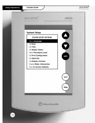
2 • Features2.3.2 The <strong>ICS</strong>-<strong>1000</strong> Control PanelsChromeleon provides two types of Control Panels for the <strong>ICS</strong>-<strong>1000</strong>.• <strong>System</strong> Control Panels are used for controlling and monitoring <strong>ICS</strong>-<strong>1000</strong> operation. <strong>System</strong> Control Panels are described below.• The Wellness Panel is used for performing calibration and diagnosticfunctions. The Wellness Panel is described in Section 5.1.<strong>System</strong> Control Panels<strong>System</strong> Control Panels for the <strong>ICS</strong>-<strong>1000</strong> are located in the DionexTemplates/Panels/Dionex_IC\<strong>ICS</strong>-<strong>1000</strong> folder. Chromeleon providespanels for each <strong>ICS</strong>-<strong>1000</strong> system configuration. There are two styles ofpanels:• Traditional system panels (see Figure 2-8) provide controls on asingle window with minimal graphics.• <strong>System</strong> panels (see Figure 2-9) provide a more graphical interfacethan the traditional style. On these panels, clicking a control oftenbrings up another window in which you enter a value.When you open a <strong>System</strong> Control Panel, select a panel that matches yoursystem configuration and choose the style that you prefer.Doc. 031879-01 3/03 2-13
<strong>ICS</strong>-<strong>1000</strong> <strong>Ion</strong> <strong>Chromatography</strong> <strong>System</strong>Figure 2-8. <strong>ICS</strong>-<strong>1000</strong> <strong>System</strong> Control Panel (Traditional)Figure 2-9. <strong>ICS</strong>-<strong>1000</strong> <strong>System</strong> Control Panel (Graphical)2-14 Doc. 031879-01 3/03
2 • Features<strong>System</strong> Controls OverviewThis section provides brief descriptions of the various controls availableon the <strong>ICS</strong>-<strong>1000</strong> <strong>System</strong> Control Panels.NOTESampleThe examples are from the traditional style of panel.DatasourceDisplays the database in which the chromatographic data for the sampleis saved.SequenceDisplays the sequence in which this sample is included.SampleDisplays the name of the sample that is running.ProgramDisplays the name of the program that is running.Elapsed TimeDisplays the time that has elapsed since the sample analysis began.Run TimeDisplays the total run time.<strong>System</strong>StartupStarts the pump and suppressor. The flow rate and suppressor currentsettings that were in effect at system shutdown (see below) are restored.ShutdownStops the pump and suppressor. The flow rate and suppressor currentsettings currently in effect are remembered and will be restored atsystem startup (see above).Doc. 031879-01 3/03 2-15
<strong>ICS</strong>-<strong>1000</strong> <strong>Ion</strong> <strong>Chromatography</strong> <strong>System</strong>Audit TrailThe Audit Trail displays an account of every event that occurs during<strong>ICS</strong>-<strong>1000</strong> operation. This includes errors, status messages, operationalevents, etc.PumpEluent BottleThe entry field and gauge indicate the levelof liquid (in liters) in the eluent bottle. Thisis a user controlled feature. The level mustbe entered by the user when the reservoir isfilled. See Section 3.4.4 for details.ConnectedConnects the <strong>ICS</strong>-<strong>1000</strong> to the ChromeleonControl Panel, enabling communicationbetween the PC and the module. Clearingthe check box disconnects the <strong>ICS</strong>-<strong>1000</strong>from the PC.Hold ModeIndicates when an automatic (batch) run is on hold; pump flow is notstopped.Stop ModeIndicates when an automatic (batch) run is stopped; pump flow is alsostopped.Flow RateSets the pump flow rate in mL/min.PressureThe sliders select the upper and lower pressure limits. The Pressure fielddisplays the current pressure.On, Off, PrimeTurn the pump on and off or start the pump priming function.2-16 Doc. 031879-01 3/03
2 • FeaturesInject ValveDisplays the current position of the injectvalve. The Inject and Load buttons select theposition.Eluent Flow ValveDisplays the current position of the eluentflow valve. The Closed and Open buttonsselect the position.Column Heater (Optional)Set TempSets the temperature of the column heater.DetectorConnectedConnects the <strong>ICS</strong>-<strong>1000</strong> to the Chromeleon Control Panel, enablingcommunication between the PC and the module. Clearing the Connectedcheck box disconnects the <strong>ICS</strong>-<strong>1000</strong> from the PC.AutozeroSets the conductivity to zero.ReadyIndicates if the detector is ready to begin data acquisition.Doc. 031879-01 3/03 2-17
<strong>ICS</strong>-<strong>1000</strong> <strong>Ion</strong> <strong>Chromatography</strong> <strong>System</strong>SignalDisplays the offset conductivity.Data RateSets the rate at which data points are recorded.Supp. TypeSelects the type of suppressor installed.SRS CurrentSets the current supplied to the suppressor.Cell TempSets the temperature of the cell.SRS ModeSelects whether the suppressor is on or off.Show PlotDisplays the <strong>ICS</strong>-<strong>1000</strong> detector signal plot in a separate window.2-18 Doc. 031879-01 3/03
2 • Features2.4 <strong>System</strong> Component DetailsThis section provides details about <strong>ICS</strong>-<strong>1000</strong> system components, including thevacuum degas assembly (optional), eluent valve, pump, injection valve, columnheater (optional), suppressor, and conductivity cell.2.4.1 Vacuum Degas Assembly (Optional)The vacuum degas assembly provides online eluent degassing at the timeand duration specified by the user. The assembly, which must be installedin the <strong>ICS</strong>-<strong>1000</strong> at the factory, consists of:• A single-channel degas chamber (with degas membranes) withinternal capacity of 17 mL• A dual-stage diaphragm vacuum pump• A solenoid valve• An on-board vacuum sensor• The electronics required to operate the vacuum pump• Tubing, fittings, and other accessoriesBy default, the <strong>ICS</strong>-<strong>1000</strong> monitors the degas pressure reading and turnsthe degas pump on and off as needed. A different degas operating modecan be selected from Chromeleon. To select degas operating options fromChromeleon, open the Server Configuration program, select the <strong>ICS</strong>-<strong>1000</strong>Doc. 031879-01 3/03 2-19
<strong>ICS</strong>-<strong>1000</strong> <strong>Ion</strong> <strong>Chromatography</strong> <strong>System</strong>device icon under the timebase, and select Properties from the Editmenu. Select the Options tab (see Figure 2-10).Figure 2-10. Server Configuration Properties: Degas Mode OptionsDegas Mode Options• Always Off: The degas pump is always off.• Always On: The degas pump is always on. This setting is for testpurposes by a Dionex Service Representative. Do not use this settingfor routine operation.• Cycle: The degas pump cycles on and off according to the timesspecified in the Cycle On and Off fields. Cycle On specifies for howlong the degas pump runs during a cycle. Cycle Off specifies the timebetween cycles.• Monitor: (default mode) The <strong>ICS</strong>-<strong>1000</strong> monitors the degas pressurereading and turns the degas pump on and off as required.2-20 Doc. 031879-01 3/03
2 • Features2.4.2 Eluent ValveThe eluent valve controls the flowfrom the eluent reservoir. It opensautomatically when the pump isrunning and closes when thepump is off. The valve can also beopened and closed manually fromthe Chromeleon Control Panel(see Section 2.3.2). This lets youperform service procedures onpump components without eluentleaks occurring.Figure 2-11. Eluent Valve2.4.3 PumpThe <strong>ICS</strong>-<strong>1000</strong> pump is a microprocessor-based isocratic eluent deliverysystem. Its variable speed, dual-piston series design ensures pulse-freepumping for the most demanding applications.Primary Pump HeadThe primary pump head pumps mobile phase into the secondary head (seeFigure 2-12). The check valves, which prevent reverse flow through thepump, are located on the bottom (inlet) and top (outlet) of the primarypump head. The priming valve is on the front of the pump head.Doc. 031879-01 3/03 2-21
<strong>ICS</strong>-<strong>1000</strong> <strong>Ion</strong> <strong>Chromatography</strong> <strong>System</strong>PressureTransducerSecondaryPump HeadWaste ValveOutlet CheckValvePrimaryPump HeadPrimingValveInlet CheckValveFigure 2-12. <strong>ICS</strong>-<strong>1000</strong> Pump ComponentsTo open the priming valve, turn the knob one-quarter to one-half turncounterclockwise. When the priming valve is open, liquid can flow intoand out of the primary pump head via the port in the front of the valve.NOTEThe priming valve must be open when the pump isbeing primed with a syringe or with isopropylalcohol. For detailed priming instructions, seeSection B.12.Secondary Pump HeadThe secondary pump head delivers eluent to the remainder of thechromatography system (injection valve, column, and detector). Thewaste valve is located on the front of the secondary pump head (seeFigure 2-12).To open the waste valve, turn the knob one-quarter to one-half turncounterclockwise. When the waste valve is in the open position, all outputis directed to waste.NOTEThe waste valve must be open when the pump isbeing primed using the Prime button. For detailedpriming instructions, see Section B.12.2-22 Doc. 031879-01 3/03
2 • FeaturesPressure TransducerFlow exiting the secondary pump head is directed to the pressuretransducer (see Figure 2-12), which measures the system pressure.Pressure measurements, which can be monitored from the ChromeleonControl Panel, indicate that the pumping system is delivering smooth,accurate flow.The system pressure should remain consistent (no more than a 3%difference from one pressure reading to the next). High and low pressurelimits can be used to stop the pump flow if a limit is exceeded. SeeSection 4.1 for troubleshooting information if a pressure limit isexceeded.Pulse DamperFlow output from the pressure transducer continues to the pulse damper,which smooths minor pressure variations. From there, flow is directed tothe injection valve and then to the remainder of the chromatographysystem.Piston Seal WashThe pump includes a piston seal wash assembly that can be set up tocontinuously rinse the back of the piston seals to remove salt crystals andprolong the life of the seals. To use this feature, an external water sourcemust be connected. See Section B.21 for connection instructions.For continued protection of the pump, replace the piston rinse seals (seeSection 5.6) and O-rings in the seal wash assembly every 6 months, orwhenever you replace the main piston seals for the <strong>ICS</strong>-<strong>1000</strong> pump.Doc. 031879-01 3/03 2-23
<strong>ICS</strong>-<strong>1000</strong> <strong>Ion</strong> <strong>Chromatography</strong> <strong>System</strong>2.4.4 Injection ValveThe injection valve (P/N 057968) is a six-port, electrically-activatedvalve. A 25-µL sample loop (P/N 042857) is installed on the valve at thefactory.The valve has two operating positions: Load and Inject (see Figure 2-13).Sample InLOAD POSITIONSample InINJECT POSITIONTo ColumnTo ColumnSampleLoopSampleLoopTo WasteFrom PumpTo WasteFrom PumpFigure 2-13. Injection Valve Flow SchematicsEluent flows through either the Load or Inject path, depending on thevalve position.• In the Load position, sample is loaded into the sample loop, where itis held until injection. Eluent flows from the pump, through the valve,and to the column, bypassing the sample loop. Sample flows from thesyringe or automated sampler line (if installed), through the valve,and into the sample loop. Excess sample flows out to waste.• In the Inject position, sample is swept to the column for analysis.Eluent flows from the pump, through the sample loop, and on to thecolumn, carrying the contents of the sample loop with it. Section 3.10describes how to inject samples.Figure 2-14 shows the injection valve connections. The injection valve isplumbed at the factory with all tubing and fittings for connection to thepump, injection port, column, and waste. A 25-µL PEEK sample loop(P/N 042857) is installed between ports L (1) and L (4). Dionex offers2-24 Doc. 031879-01 3/03
2 • Featuressample loops in various sizes. If necessary, the pre-installed 25-µL loopcan be replaced with a loop that has a different sample injection volume.Figure 2-14. Injection Valve PlumbingDoc. 031879-01 3/03 2-25
<strong>ICS</strong>-<strong>1000</strong> <strong>Ion</strong> <strong>Chromatography</strong> <strong>System</strong>2.4.5 Column Heater (Optional)The column heater provides temperaturecontrol for the separator and guard column.The heater temperature can be set to between30 °C and 60 °C and it must be set at least5 °C above the ambient temperature.Temperature is monitored via a thermistormounted in the heater block. Setting thetemperature to 0 °C turns off the columnheater.If the temperature exceeds 65 °C, the columnheater is shut off and the error message“Column heater exceeds safe temperature.”is displayed in Chromeleon. See Section 4.1for troubleshooting information.The column heater can either be installed atthe factory or ordered separately (P/N058060).Figure 2-15. Column Heater2-26 Doc. 031879-01 3/03
2 • Features2.4.6 SuppressorThe suppressor reduces the eluent conductivity and enhances theconductivity of the sample ions, thereby increasing detection sensitivity.Either an Atlas Electrolytic Suppressor, Self-Regenerating Suppressor, orMicroMembrane Suppressor can be used with the <strong>ICS</strong>-<strong>1000</strong>.For details about any of the suppressors or for information about selectinga suppressor for your application, refer to the suppressor manuals. Themanuals are on the Dionex Reference Library CD-ROM (P/N 053891),located in the <strong>ICS</strong>-<strong>1000</strong> Ship Kit (P/N 057905).2.4.7 DS6 Heated Conductivity CellThe <strong>ICS</strong>-<strong>1000</strong> flow-through conductivity cell measures the electricalconductance of analyte ions as they pass through the cell. Two passivated316 stainless steel electrodes are permanently sealed into the PEEK cellbody. The cell design provides efficient sweep-out, low volume (1 µL),and low dispersion. Temperature control and compensation help ensuregood peak reproducibility and baseline stability.Temperature ControlTemperature directly affects the conductivity of a solution. For example,laboratory heating and air conditioning systems can cause a regular slowcycling in the baseline. This, in turn, can affect the reproducibility of ananalysis. The higher the conductivity, the more pronounced the effect.In ion analysis, the effect of temperature variation is minimized bysuppressing eluent conductivity. To further reduce the effect oftemperature variation, the <strong>ICS</strong>-<strong>1000</strong> provides temperature control to thecell. A heater inside the cell regulates the temperature. The cell heater canbe set to between 30 °C and 55 °C. The set temperature must be at least7 °C above the ambient temperature. Setting the cell temperature to 0 °Cturns off the cell heater.Temperature CompensationBuilt-in preset temperature compensation of 1.7% per °C helps minimizechanges in the baseline or in peak heights if the operating temperature isdifferent from the temperature at which the cell was calibrated.Doc. 031879-01 3/03 2-27
<strong>ICS</strong>-<strong>1000</strong> <strong>Ion</strong> <strong>Chromatography</strong> <strong>System</strong>DS6 Heated Conductivity Cell ComponentsThe cell front cover provides CELL IN and CELL OUT fittings forconnecting the cell to the suppressor (see Figure 2-4). The remaining cellcomponents are mounted behind the component panel. To replace, the cellremove the screws on the cell front cover and pull the entire cell assemblyout through the component panel. See Section 5.9 for cell replacementinstructions.2-28 Doc. 031879-01 3/03
3 • Operation and MaintenanceThis chapter describes routine operating and maintenance procedures for the <strong>ICS</strong>-<strong>1000</strong> <strong>Ion</strong> <strong>Chromatography</strong> <strong>System</strong>.3.1 Operation OverviewFigure 3-1 illustrates the basic steps for routine operation of the <strong>ICS</strong>-<strong>1000</strong>.Power up the systemStart ChromeleonSet up the reservoirCheck allconnectionsPrime the pumpSet operatingconditionsEquilibrate thesystemPrepare samplesVerify operatingstatusProcess samplesFigure 3-1. <strong>ICS</strong>-<strong>1000</strong> Operation Flow ChartDoc. 031879-01 3/03 3-1
<strong>ICS</strong>-<strong>1000</strong> <strong>Ion</strong> <strong>Chromatography</strong> <strong>System</strong>Sample Processing OverviewSamples can be run either manually (one at a time), or they can be grouped andrun automatically in batches. Figure 3-2 shows the typical steps for manual andbatch sample processing. Samples can be loaded into the sample loop with anautosampler or with a syringe through the injection port on the <strong>ICS</strong>-<strong>1000</strong> frontdoor.<strong>Manual</strong> SampleProcessingUsing ChromeleonLoad the sampleBatch SampleProcessingUsing ChromeleonCreate a Sequence(Sequence Wizard)Start dataacquisitionAdd the Sequenceto the BatchAutozeroStart the BatchInject the sampleStop dataacquisition(Optional)Save the manualsequence dataFigure 3-2. Sample Processing Overview3-2 Doc. 031879-01 3/03
3 • Operation and Maintenance3.2 Power Up the <strong>System</strong>PowerSwitchPress the power switch on the <strong>ICS</strong>-<strong>1000</strong> rear panel (see Figure 3-3) toturn on the system power. Table 3-2shows the <strong>ICS</strong>-<strong>1000</strong> conditions atpower up.Also turn on the power to thecomputer and the autosampler (ifused).Figure 3-3. <strong>ICS</strong>-<strong>1000</strong> Rear PanelFeaturePumpInjection valveCellSuppressorCell heaterColumn oven temperature(Optional)Power-Up ConditionOffLoad positionReading current valueOff*Set to the last value used. The default when the<strong>ICS</strong>-<strong>1000</strong> is turned on for the first time is 35 °C.Set to the last value used. The default when the<strong>ICS</strong>-<strong>1000</strong> is turned on for the first time is 30 °C.Table 3-2. <strong>ICS</strong>-<strong>1000</strong> Power-Up Conditions* When you start the suppressor, the value used last is restored.Doc. 031879-01 3/03 3-3
<strong>ICS</strong>-<strong>1000</strong> <strong>Ion</strong> <strong>Chromatography</strong> <strong>System</strong>3.3 Start ChromeleonNOTESee Section B.8 for how to set up Chromeleon, if you arebeginning operation of an <strong>ICS</strong>-<strong>1000</strong> that has not beenconfigured in a timebase.1. If the Chromeleon Server is not running (the icon on the taskbar is crossed outin red ), start the Server by right-clicking the icon and selecting StartServer. When the server starts, the icon changes to gray .2. Start Chromeleon by selecting Start>Programs>Chromeleon>Chromeleon. The Chromeleon main window and the Browser will open.Your screen display should resemble Figure 3-4. If the Browser does notopen, select Browser from the File menu to open it.Figure 3-4. Chromeleon Main Window and Browser3-4 Doc. 031879-01 3/03
3 • Operation and Maintenance3. In the Browser, expand the Dionex Templates\Panels\Dionex_IC\<strong>ICS</strong>-<strong>1000</strong><strong>System</strong> Panels folder. Several <strong>ICS</strong>-<strong>1000</strong> <strong>System</strong> Control Panels (.PAN files)are provided, corresponding to various system configurations. There are twostyles of panels:• Traditional panels provide controls on a single window with minimalgraphics.• <strong>System</strong> panels provide a more graphical interface than the traditional styleand include more controls. You can choose either style of panel,depending on your personal preference.4. Open a panel for your system configuration by double-clicking its name in thelist. For example, if your system includes an <strong>ICS</strong>-<strong>1000</strong> and an AS50autosampler, double-click either <strong>ICS</strong>-<strong>1000</strong>_Traditional_<strong>System</strong>_AS50.panor <strong>ICS</strong>-<strong>1000</strong>_<strong>System</strong>_AS50.pan.5. The Control Panel opens, unconnected (see Figure 3-5). To connect to thetimebase, open the Control menu and click the name of the <strong>ICS</strong>-<strong>1000</strong>timebase from the list at the bottom of the menu.Figure 3-5. <strong>ICS</strong>-<strong>1000</strong> <strong>System</strong> Control Panel (Unconnected)Doc. 031879-01 3/03 3-5
<strong>ICS</strong>-<strong>1000</strong> <strong>Ion</strong> <strong>Chromatography</strong> <strong>System</strong>Figure 3-6 shows a connected Control Panel for an <strong>ICS</strong>-<strong>1000</strong> system.Figure 3-6. <strong>ICS</strong>-<strong>1000</strong> <strong>System</strong> Control Panel (Connected)NOTEThe <strong>ICS</strong>-<strong>1000</strong> <strong>Ion</strong> <strong>Chromatography</strong> <strong>System</strong> is designedfor use for IC (ion chromatography) and BioLCapplications and should not be used for any otherpurpose. If there is a question regarding appropriateusage, contact Dionex.3.4 Set Up the Eluent Reservoir3.4.1 Prepare the EluentPrepare the eluent according to the instructions in the column manual.Column manuals are included on the Dionex Reference Library CD-ROM(P/N 053891).3.4.2 Degas the EluentEluent quality significantly affects the performance of the <strong>ICS</strong>-<strong>1000</strong>. Toensure optimal pump performance, observe the following precautions:3-6 Doc. 031879-01 3/03
3 • Operation and Maintenance• Dionex strongly recommends vacuum degassing all eluents. Thishelps prevent bubbles, caused by outgassing, from forming in thepump heads and the detector flow cell.• The optional vacuum degas assembly provides programmable, onlinedegassing. The degas assembly must be installed in the <strong>ICS</strong>-<strong>1000</strong> atthe factory. If the <strong>ICS</strong>-<strong>1000</strong> does not contain a degas assembly,manually degas eluents daily (following the instructions below) andstore it in pressurized reservoirs.<strong>Manual</strong> Degassing of Eluent1. Prepare the eluent required for the application and pour it into avacuum flask1. Pour the deionized water into a vacuum flask2. Attach the flask to a vacuum pump or water aspirator.3. Vacuum degas the eluent deionized water for 5 to 10 minutes byshaking or sonication.4. Remove the flask from the vacuum. Do not allow water to flowfrom the aspirator back into the flask.5. Pour the degassed eluent deionized water into a pressurizablereservoir. Do not shake the eluent.6. Install an end-line filter on the eluent deionized water line (seeSection 3.4.3).7. Pressurize the reservoir (see Section B.20).3.4.3 Filter the EluentFiltering removes small particulates in the eluent that may contaminatethe pump check valves and cause erratic flow rates or loss of prime. Anend-line filter (P/N 045987) is provided in the <strong>ICS</strong>-<strong>1000</strong> Ship Kit(P/N 057905) for this purpose.Install the end-line filter on the end of the eluent line, inside the reservoir.Verify that the end of the filter extends to the bottom of the reservoir andthat the filter is submerged in eluent. This prevents air from being drawnthrough the lines. Refer to the Pressurizable Reservoir InstallationInstructions for details.Doc. 031879-01 3/03 3-7
<strong>ICS</strong>-<strong>1000</strong> <strong>Ion</strong> <strong>Chromatography</strong> <strong>System</strong>3.4.4 Fill the ReservoirFill the reservoir with the prepared eluent.3.4.5 Set the Eluent LevelAfter filling the reservoir, enter the volume of liquid in the reservoir onthe Chromeleon Control Panel (see Figure 3-6). The <strong>ICS</strong>-<strong>1000</strong> determinesthe eluent usage by monitoring the flow rate and the length of time thepump is on, and updates the Eluent Level field as the eluent is used up. Awarning first appears if the level falls below 200 mL. Warnings arerepeated at 100 mL and 0 mL.In order for the eluent level displayed on the Control Panel to beaccurate, the level must be entered by the user when the reservoir isfilled. The <strong>ICS</strong>-<strong>1000</strong> does not automatically detect when the reservoiris filled, nor when it is empty.Enter the volume ofliquid in the reservoirNote: The Eluent Bottlefield and slider gaugeare updated as theliquid is used up.Figure 3-7. Setting the Eluent Level3.4.6 Connect the ReservoirIf it is not already connected, connect the ELUENT BOTTLE OUT line fromthe reservoir cap to the ELUENT IN line, which extends from the plumbingand cable chase on the top of the <strong>ICS</strong>-<strong>1000</strong>.3-8 Doc. 031879-01 3/03
3 • Operation and Maintenance3.5 Check All Connections1. Make sure the reservoir is filled and the tubing connecting the reservoir to the<strong>ICS</strong>-<strong>1000</strong> tubing is securely connected.2. Make sure the USB cable from the computer is connected to the USBreceptacle on the <strong>ICS</strong>-<strong>1000</strong> rear panel.3.6 Prime the PumpIf you changed eluent or if the eluent lines are dry, prime the lines firstwith a syringe before priming the pump. See Section B.14.1 forinstructions.1. Verify that the priming valve on the primary pump head (see Figure 3-8) isclosed (turned all the way clockwise).2. Open the waste valve on the secondary pump head by turning the knob onequarterto one-half turn counterclockwise. Opening the valve directs theeluent flow path to waste and eliminates backpressure.SecondaryPump HeadWaste Valve(open)Priming Valve(close)PrimaryPump HeadFigure 3-8. Priming the Pump3. Press Prime on the Chromeleon Control Panel. A confirmation message isdisplayed, asking if you opened the waste valve. Select Yes. The pump willbegin pumping at approximately 3.0 mL/min.4. Continue priming the <strong>ICS</strong>-<strong>1000</strong> until all air and previous eluent are purgedand no air bubbles are exiting the waste line.Doc. 031879-01 3/03 3-9
<strong>ICS</strong>-<strong>1000</strong> <strong>Ion</strong> <strong>Chromatography</strong> <strong>System</strong>5. Press Pump Off.6. Close the waste valve. Do not overtighten. The pump is now ready foroperation.3.7 Set <strong>System</strong> Operating ConditionsNOTEThis section is an overview of the steps needed to startup the system and begin running samples. Actualoperating parameters (flow rate, cell heatertemperature, suppressor current, etc.) depend on theapplication to be run. Refer to the column manual forthe required parameters for your application.Set or verify system operating parameters from the Chromeleon Control Panel.Operating parameters can also be set automatically by loading a Chromeleonsequence.NOTEClicking the <strong>System</strong> Startup button on the ChromeleonControl Panel, starts the pump and suppressor. The flowrate and suppressor current settings that were in effectwhen the system was shut down are restored.1. Verify that the pump is on and set to the correct flow rate.2. Verify that the suppressor current is on and that the setting is correct.3. Verify that the cell heater is set to the correct value.4. Verify that the column heater is set to the correct value.3-10 Doc. 031879-01 3/03
3 • Operation and Maintenance3.8 Equilibrate the <strong>System</strong> and Verify Operational Status1. Allow the system to equilibrate. During equilibration, the ChromeleonControl Panel displays the background conductivity (the conductivity of theeluent before sample injection) and the system backpressure.2. Monitor the background conductivity. Refer to the column manual for theappropriate background conductivity for your application.3. Offset the background and zero the reading by clicking the Autozero buttonon the Chromeleon Control Panel (see Figure 3-4).4. Monitor the system pressure from the Control Panel to make sure it is at theexpected pressure for the installed column (refer to the column manual fordetails) and it stable.• If the pressure is less than the expected amount, gas may be trapped in thesystem. Release the gas by removing the pump fitting on the injectionvalve port, labeled P (2). Allow the air to escape and then reconnect thefitting.• If the pressure fluctuates by more than about 0.13 MPa (20 psi), prime thepump. See Section 4.3 for additional troubleshooting information.• If the pressure is too high, there may be a restriction in the systemplumbing. See Section 4.7 for troubleshooting information.5. Verify that the baseline conductivity is at the expected reading for yourapplication and is stable. In general, it should be
<strong>ICS</strong>-<strong>1000</strong> <strong>Ion</strong> <strong>Chromatography</strong> <strong>System</strong>3.9 Prepare SamplesNOTESample preparation can be performed while the systemis equilibrating.3.9.1 Collecting and Storing SamplesCollect samples in high density polyethylene containers that have beenthoroughly cleaned with deionized (DI) water. Do not clean containerswith strong acids or detergents because these can leave traces of ions onthe container walls. The ions may interfere with the analysis.If samples will not be analyzed on the day they are collected, filter themthrough clean 0.45 µm filters immediately after collection; otherwise,bacteria in the samples may cause the ionic concentrations to change overtime. Refrigerating the samples at 4° C (39° F) will reduce, but noteliminate, bacterial growth.Analyze samples containing nitrite or sulfite as soon as possible. Nitriteoxidizes to nitrate, and sulfite to sulfate, thus increasing the measuredconcentrations of these ions in the sample. In general, samples that do notcontain nitrite or sulfite can be refrigerated for at least one week with nosignificant changes in anion concentrations.3.9.2 Pretreating SamplesAnalyze rainwater, drinking water, and air particulate leach solutionsdirectly with no sample preparation (other than filtering and possiblydiluting).Filter groundwater and wastewater samples through 0.45 µm filtersbefore injection, unless samples were filtered after collection.Before injection, pretreat samples that may contain high concentrations ofinterfering substances by putting them through Dionex OnGuard®cartridges. Refer to the Installation and Troubleshooting Guide forOnGuard Cartridges (Document No. 032943) for instructions.3-12 Doc. 031879-01 3/03
3 • Operation and Maintenance3.9.3 Diluting SamplesBecause the concentrations of ionic species in different samples can varywidely from sample to sample, no single dilution factor can berecommended for all samples of one type. In some cases (for example,many water samples), concentrations are so low that dilution is notnecessary.Use eluent or ASTM filtered, Type I (18-megohm) deionized water oreluent to dilute the sample. When using carbonate eluents, diluting witheluent minimizes the effect of the water dip at the beginning of thechromatogram. If you dilute the sample with eluent, also use eluent fromthe same lot to prepare the calibration standards. This is most importantfor fluoride and chloride, which elute near the water dip.To improve the accuracy of early eluting peak determinations, such asfluoride, at concentrations below 50 ppb, dilute standards in eluent orspike the samples with concentrated eluent to minimize the water dip. Forexample, spike a 100 mL sample with 1.0 mL of a 100 X eluentconcentrate.Doc. 031879-01 3/03 3-13
<strong>ICS</strong>-<strong>1000</strong> <strong>Ion</strong> <strong>Chromatography</strong> <strong>System</strong>3.10 Loading and Injecting SamplesSamples can be loaded into the sample loop through the injection port on the frontdoor using a syringe or vacuum syringe, or they can be loaded using anautosampler.For autosampler injections, the injection port tubing is disconnected from the <strong>ICS</strong>-<strong>1000</strong> injection valve and replaced by the autosampler outlet tubing. Other setuprequirements depend upon the model of autosampler.Setup for an AS40 AutosamplerA relay or TTL connection is required for Chromeleon to control sample loading.See Section B.18 for AS40 autosampler installation instructions.Setup for an AS50 AutosamplerTo use an AS50 autosampler with the <strong>ICS</strong>-<strong>1000</strong>, the AS50 must meet thefollowing requirements:• An injection valve cannot be installed in the AS50• The AS50 must have Moduleware version 1.11 or later installed• Control of the <strong>ICS</strong>-<strong>1000</strong> injection valve must be enabled in the AS50The following AS50 models are configured at the factory to meet the aboverequirements:• AS50 without injection valve (P/N 061309)• AS50 without injection valve; with sample preparation (P/N 061310)• AS50 without injection valve; with sample preparation and sample traycooling (P/N 061311)• AS50 without injection valve; with sample tray cooling (P/N 061312)See Section B.17 for AS50 autosampler installation instructions.After the AS50 is configured for use with the <strong>ICS</strong>-<strong>1000</strong>, all AS50 modes ofinjection (full-loop, partial-loop, and partial-loop limited-sample) are supported.In addition, all AS50 injection valve commands (whether issued from the AS50front panel or from Chromeleon) will control the <strong>ICS</strong>-<strong>1000</strong> injection valve. ForChromeleon control, the AS50 must be added to the <strong>ICS</strong>-<strong>1000</strong> timebase (seeSection B.8). For front panel control, the AS50 and <strong>ICS</strong>-<strong>1000</strong> can be set up for3-14 Doc. 031879-01 3/03
3 • Operation and Maintenancestand-alone operation. This requires a TTL cable connection between the AS50and the <strong>ICS</strong>-<strong>1000</strong>. See Section C.3 for stand-alone setup instructions.3.10.1 Loading Samples with a Syringe1. Make sure the injection port on the <strong>ICS</strong>-<strong>1000</strong> front door (seeFigure 2-1) is connected to the sample port S (5) on the injection valve(see Figure 3-9).Figure 3-9. Injection Valve Connections2. Fill the 1 cc syringe (P/N 016388) provided in the <strong>ICS</strong>-<strong>1000</strong> Ship Kit(P/N 057905) with a calibration standard or sample.3. Insert the syringe into the injection port on the <strong>ICS</strong>-<strong>1000</strong> front door.4. Verify that the injection valve is in the Load position.5. Overfill the sample loop with several sample loop volumes. Excesssample will exit through the injection valve waste line.6. Leave the syringe in the port.7. Switch the injection valve to the Inject position (see Section 3.10.4).Doc. 031879-01 3/03 3-15
<strong>ICS</strong>-<strong>1000</strong> <strong>Ion</strong> <strong>Chromatography</strong> <strong>System</strong>3.10.2 Loading Samples with a Vacuum Syringe1. Disconnect the waste line from port W (6) of the injection valve (seeFigure 3-9) and attach a shorter line: 25 to 30 cm (10 to 12 inches) ofPEEK or Teflon® tubing.2. Place the free end of the line into the sample.3. Verify that the injection valve is in the Load position.4. Insert the 1 cc syringe (P/N 016388) provided in the <strong>ICS</strong>-<strong>1000</strong> ShipKit (P/N 057905) into the injection port on the <strong>ICS</strong>-<strong>1000</strong> front door(see Figure 2-1) and pull out the plunger to draw the sample into theinjection valve.5. Switch the injection valve to the Inject position (see Section 3.10.4).3.10.3 Loading Samples with an Autosampler1. Verify that the autosampler output line is connected to port S (5) of the<strong>ICS</strong>-<strong>1000</strong> injection valve.2. Prepare and fill the sample vials and place them in the autosamplertray or cassette. Refer to the autosampler manual for detailedinstructions.3. The sample loading process depends on the autosampler. Refer to theautosampler manual for detailed instructions. In general, use one ofthe following methods:• Include the commands for controlling sample loading in aChromeleon program. See the examples in Section 3.10.5.• Enter the commands for loading the sample from the autosamplerfront panel.4. Switch the injection valve to the Inject position (see Section 3.10.4).NOTEIf you are running the <strong>ICS</strong>-<strong>1000</strong> withoutChromeleon control, see Section C.3 for standalonesetup and operation instructions using anAS50 autosampler.3-16 Doc. 031879-01 3/03
3 • Operation and Maintenance3.10.4 Injecting SamplesAfter loading the sample in the sample loop, switch the injection valve tothe Inject position, using one of the following methods:• <strong>Manual</strong>ly: Click the Inject button on the Chromeleon Control Panel(see Figure 3-6).• Automatically: Include the Inject command in a Chromeleonprogram. See the examples in Section 3.10.5.3.10.5 Example Chromeleon Commands for Loading andInjecting SamplesThe following examples show commands for loading and injectingsamples using an AS50 or AS40 autosampler.Example AS50 Program Commands0.000 Pump_ECD.Autozero ;Zero the baseline.Load;Switch the valve to Load.Wait CycleTimeState ;Wait for cycle time (if any).Inject;Switch the valve to Inject.Wait InjectState ;Wait for injection to complete.ECD_1.AcqOn;Start data acquisition.14.000 ECD_1.AcqOff ;Stop data acquisition.Example AS40 Program Commands-2.300 Pump_ECD_Relay_1.Closed Duration=138.00 ;Note 10.000 Pump_ECD.Autozero ;Note 2ECD_1.AcqOn ;Note 3Pump_InjectValve.InjectPosition Duration=30.00 ;Note 430.00 ECD_1.AcqOff ;Note 5Doc. 031879-01 3/03 3-17
<strong>ICS</strong>-<strong>1000</strong> <strong>Ion</strong> <strong>Chromatography</strong> <strong>System</strong>AS40 Program Command Notes:1. Close the <strong>ICS</strong>-<strong>1000</strong> RELAY OUT 1, which is connected to the AS40LOAD relay. This signals the AS40 to load the sample.2. Zero the baseline.3. Start data acquisition.4. Switch the valve to Inject.5. Stop data acquisition.3.11 Process SamplesSamples can be run either manually (one at a time) or automatically (in groups or“batches”).3.11.1 <strong>Manual</strong> Sample ProcessingTo process samples manually, select operating parameters and commandsfrom the Chromeleon menu bar, toolbars, and Control Panel. Commandsare executed as soon as they are entered.1. Complete the steps in Sections 3.2 through 3.8 to prepare foroperation and start up the <strong>ICS</strong>-<strong>1000</strong>.2. Load the sample using a syringe, vacuum syringe, or autosampler(see Section 3.10).3. Select Acquisition On from the Control menu. Chromeleon recordsthe signal supplied by the detector and displays the signal plot on theControl Panel.4. Click the Autozero button on the Control Panel.5. Inject the sample (see Section 3.10.4).6. Monitor the chromatogram on the Control Panel and selectAcquisition Off from the Control menu when sample data iscollected.NOTEData from Chromeleon manual processing is savedin the MANUAL sequence folder under the localdatasource. This data is overwritten each time a3-18 Doc. 031879-01 3/03
3 • Operation and Maintenancenew manual sample is processed. To save the datafrom a manual run, select the MANUAL folder,select Save As from the File menu, and enter a newname for the sequence.3.11.2 Automatic (Batch) Sample ProcessingFor batch processing, you use Chromeleon to create a list of samples (asequence) to be processed automatically. For each sample, the sequenceincludes a program with commands and parameters for controlling the<strong>ICS</strong>-<strong>1000</strong>, controlling the autosampler (if used), and acquiring sampledata. The sequence also includes a quantification method for peakidentification and area determination. Additional sample processingparameters are included in the sequence (for example, the sample name,sample type, injection volume, etc.).After defining the sequence, you can start batch processing.1. Complete the steps in Sections 3.2 through 3.8 to prepare foroperation and to start up the <strong>ICS</strong>-<strong>1000</strong>.2. Create a new sequence or modify an existing one.To create a new sequence:a. In the Browser, select File>New. Select Sequence (usingWizard) and click OK.b. Complete the steps in the Sequence Wizard, adding the desirednumber of samples and standards to the list. For help with any ofthe steps, click the Help button on the Sequence Wizard page.NOTEA simple way to get started is to select the “UseApplication Template” option in Step 4 of theSequence Wizard. This option lets you select acolumn and suppressor type from a list ofapplications. The Wizard then copies a programand quantification method, appropriate for theselected application, to the sequence folder and addsthem to the sequence definition.Doc. 031879-01 3/03 3-19
<strong>ICS</strong>-<strong>1000</strong> <strong>Ion</strong> <strong>Chromatography</strong> <strong>System</strong>3. To start the sample processing, make sure the <strong>System</strong> Control Panel isopen (see Section 3.3) and is the active window. Then, select Editfrom the Batch menu. The Batch dialog box opens (see Figure 3-10).Figure 3-10. Batch Dialog Box4. Click the Add button on the Batch List tab and add the sequence youcreated in Step 2. See Figure 3-11 for an example.Figure 3-11. Batch Dialog Box with an Example Sequence Added to the Batch List5. To start the batch, click Start.3-20 Doc. 031879-01 3/03
3 • Operation and Maintenance3.12 MaintenanceThis section describes routine maintenance procedures that users may perform.All other maintenance procedures must be performed by Dionex personnel.As Needed• Regularly check the eluent reservoir to see if it needs to be refilled.• Make fresh eluent as needed.Daily• Check the <strong>ICS</strong>-<strong>1000</strong> component mounting panel (see Figure 2-4) for leaks orspills. Wipe up spills. Isolate and repair leaks (see Section 4.2). Rinse off anydried eluent with deionized water.• Check the waste container daily and empty when needed.Weekly• Once a week, check fluid lines for crimping or discoloration. Relocate anypinched lines. Replace damaged lines.• Check the junctions between the pump heads and the pump casting forevidence of liquid leaks. If piston seal wash tubing is not connected, check thedrain tubes at the rear of the pump heads for evidence of moisture. Normalfriction and wear may gradually result in small liquid leaks around the pistonseal. If unchecked, these leaks can gradually contaminate the piston housing,causing the pump to operate poorly. If leaks occur, replace the piston seals(see Section 5.6).• Check the end-line filter (P/N 045987) and change if needed. When new, endlinefilters are pure white. If the system is in continuous operation, change theend-line filter weekly, or whenever it becomes discolored. Replace the filtermore often if bacterial buildup is visible or if the eluent does not containsolvent.NOTEIt is especially important to regularly replace end-linefilters when using aqueous eluents, which maycontaminate the filter with bacteria or algae. Thebacterial buildup may not be visible.Doc. 031879-01 3/03 3-21
<strong>ICS</strong>-<strong>1000</strong> <strong>Ion</strong> <strong>Chromatography</strong> <strong>System</strong>Every Six Months• Calibrate the cell (see Section 5.1.2).• Calibrate the vacuum degas assembly (see Section 5.1.4).• Replace the pump piston rinse seals and piston seals (see Section 5.6).Yearly• Rebuild the injection valve (see Section 5.4).• Replace the AS40 Automated Sampler tip and tubing. The AS40/ASMMaintenance Kit (P/N 055647) contains all of the components required toreplace the sampling tip and the tubing between the tip and the injectionvalve. Instructions are included with the kit.• Perform the AS50 preventive maintenance procedure. The AS50 MaintenanceKit (P/N 060581) contains all of the required components and instructions forperforming the procedure.3-22 Doc. 031879-01 3/03
4 • TroubleshootingThis chapter is a guide to troubleshooting problems that may occur whileoperating the <strong>ICS</strong>-<strong>1000</strong> <strong>Ion</strong> <strong>Chromatography</strong> <strong>System</strong>.• Section 4.1 describes error messages and how to troubleshoot them. Table 4-3lists the messages and the page numbers where they are described.• The remaining sections in this chapter describe other operating problems andhow to resolve them. Table 4-4 lists the operating problems and the pagenumbers where they are describedIf you are unable to eliminate a problem, contact Dionex for help. In the U.S., callDionex Technical Support at 1-800-346-6390. Outside the U.S., call the nearestDionex officeAlarms and Error ConditionsSeeCOLUMN HEATER EXCEEDS SAFE TEMPERATURE page 4-3COLUMN HEATER OPEN CIRCUIT page 4-3COLUMN HEATER SHORT CIRCUIT page 4-3DEGAS CALIBRATION FAILED page 4-4HARDWARE NOT PRESENT page 4-4LEAK SENSOR WET page 4-4LOAD/INJECT VALVE ERROR page 4-5OPTION NOT INSTALLED page 4-5PRESSURE SLOPE CALIBRATION ERROR page 4-5PUMP MOTOR LOST CONTROL page 4-6PUMP PRESSURE HARDWARE ERROR page 4-6PUMP OVER PRESSURE page 4-6PUMP UNDER PRESSURE page 4-7SUPPRESSOR OVER CURRENT page 4-7SUPPRESSOR OVER VOLTAGE page 4-8SUPPRESSOR OVER POWER page 4-8SUPPRESSOR NOT CONNECTED page 4-8Table 4-3. <strong>ICS</strong>-<strong>1000</strong> Alarms and Error Messages SummaryDoc. 031879-01 3/03 4-1
<strong>ICS</strong>-<strong>1000</strong> <strong>Ion</strong> <strong>Chromatography</strong> <strong>System</strong>Alarms and Error ConditionsSeeSUPPRESSOR STOPPED FOR FLOW RATE page 4-9Table 4-3. <strong>ICS</strong>-<strong>1000</strong> Alarms and Error Messages Summary (Continued)Other Operating ProblemsSeeLiquid Leaks page 4-9Pump Difficult to Prime or Loses Prime page 4-11Pump Does Not Start page 4-13No Flow page 4-14Erratic Flow/Pressure Reading page 4-15Excessive <strong>System</strong> Backpressure page 4-15Peak “Ghosting” page 4-16Nonreproducible Peak Height or Retention Time page 4-17Abnormal Retention Time or Selectivity page 4-17No Cell Response page 4-18High Cell Output page 4-18Baseline Noise or Drift page 4-19Vacuum Degas Assembly Does Not Run page 4-20Table 4-4. Operating Problems Summary4-2 Doc. 031879-01 3/03
4 • Troubleshooting4.1 Alarms and Error ConditionsIf any of the following alarm conditions occurs, a message is displayed in theChromeleon Audit Trail.COLUMN HEATER EXCEEDS SAFE TEMPERATUREThis error occurs when the column heater temperature is higher than themaximum allowed. This error may occur if the <strong>ICS</strong>-<strong>1000</strong> is operating in anextreme environment (greater than 40 °C).To troubleshoot:• Refer to Section A.3 for environmental specifications.COLUMN HEATER OPEN CIRCUITThis error message occurs when the column heater is unplugged from thecomponent panel.To troubleshoot:1. Check that the column heater is correctly plugged into the componentpanel.2. If the error persists, the column heater may be faulty. Replace thecolumn heater (see Section 5.11).COLUMN HEATER SHORT CIRCUITThis error occurs when there is a short circuit on the thermistor input used tomeasure the column heater temperature. This error indicates a faulty columnheater.To troubleshoot:• Replace the column heater (see Section 5.11).Doc. 031879-01 3/03 4-3
<strong>ICS</strong>-<strong>1000</strong> <strong>Ion</strong> <strong>Chromatography</strong> <strong>System</strong>DEGAS CALIBRATION FAILEDThis error occurs when the degas vacuum does not reach the expected levelduring calibration.To troubleshoot:1. Retry the calibration.2. If calibration still fails, the vacuum degas assembly may need to bereplaced. Contact Dionex for assistance.HARDWARE NOT PRESENTThis error indicates an error in the <strong>ICS</strong>-<strong>1000</strong> electronics.To troubleshoot:• Contact Dionex for assistance. The <strong>ICS</strong>-<strong>1000</strong> electronics componentscannot be serviced by the user.LEAK SENSOR WETThe leak sensor is installed in the drip tray at the bottom of the componentpanel (see Figure 2-4). If liquid accumulates in the tray, the sensor signals theproblem and the “Leak sensor wet” error message appears.To troubleshoot:1. Locate the source of the leak by visually inspecting the tubing,fittings, and components on the component panel.2. Tighten fittings or replace tubing and fittings as required. Refer toSection 4.2 for detailed troubleshooting of various types of leaks.3. After fixing the leak, dry the drip tray thoroughly to prevent the leaksensor from triggering additional error messages.4-4 Doc. 031879-01 3/03
4 • TroubleshootingLOAD/INJECT VALVE ERRORIf the injection valve fails to switch position within 1 second of being toggled,the <strong>ICS</strong>-<strong>1000</strong> Moduleware reports an error to Chromeleon and the“Load/Inject valve error” message appears.To troubleshoot:1. If a sequence is being executed, terminate the sequence by selectingStop on the Chromeleon Batch menu.2. Turn off the <strong>ICS</strong>-<strong>1000</strong> power briefly and then restart.3. Try to toggle the valve from Load to Inject by clicking the Load andInject buttons on the <strong>ICS</strong>-<strong>1000</strong> Control Panel in Chromeleon.4. If the problem persists, contact Dionex for assistance.OPTION NOT INSTALLEDThis error occurs if a command is issued to control an option that is notinstalled.To troubleshoot:• Check the Chromeleon Server Configuration program to verify that theoption is enabled.PRESSURE SLOPE CALIBRATION ERRORThis error occurs if you try to calibrate the pressure slope when the pressure isless than 3 MPa (500 psi).To troubleshoot:• This is a service level error message. Contact Dionex for assistance.Doc. 031879-01 3/03 4-5
<strong>ICS</strong>-<strong>1000</strong> <strong>Ion</strong> <strong>Chromatography</strong> <strong>System</strong>PUMP MOTOR LOST CONTROLThis error indicates an error in the pump controller electronics.To troubleshoot:• Contact Dionex for assistance. The <strong>ICS</strong>-<strong>1000</strong> electronics componentscannot be serviced by the user.PUMP PRESSURE HARDWARE ERRORThis error indicates an error in the pump controller electronics.To troubleshoot:• Contact Dionex for assistance. The <strong>ICS</strong>-<strong>1000</strong> electronics componentscannot be serviced by the user.PUMP OVER PRESSUREThe <strong>ICS</strong>-<strong>1000</strong> has a maximum system pressure limit of 34.5 MPa (5000 psi).The pressure limit can be lowered from Chromeleon (in the ServerConfiguration or in the control program). If the system pressure exceeds theset limit for at least 0.5 seconds, the pump stops and the “Pump over pressure”error message appears.To troubleshoot:1. Check for blockages in the liquid lines by working your waybackward from the cell to the pump. See Figure 2-6 for the flowschematic).2. Check that the flow rate is set to the correct value.3. Check that the high pressure limit is set to the correct value.4. Restart the pump.4-6 Doc. 031879-01 3/03
4 • TroubleshootingPUMP UNDER PRESSUREThe <strong>ICS</strong>-<strong>1000</strong> has a minimum pressure limit of 0. The low pressure limit canbe raised from Chromeleon (in the Server Configuration or in the controlprogram). If the system pressure falls below the low pressure limit, the pumpstops and the “Pump under pressure” error message appears.To troubleshoot:1. Make sure the eluent reservoir is full.2. Check for liquid leaks (see Section 4.2).3. Check that the waste valve is closed.4. Prime the pump (see Section B.12).5. Restart the pump.SUPPRESSOR OVER CURRENTThis error may be caused by an exhausted or dirty suppressor or by amalfunction in the suppressor controller electronics.To troubleshoot:1. Follow the instructions in the suppressor manual to regenerate thesuppressor. Suppressor manuals are included on the DionexReference Library CD-ROM (P/N 053891), located in the <strong>ICS</strong>-<strong>1000</strong>Ship Kit (P/N 057905).2. Follow the instructions in the suppressor manual to clean thesuppressor.3. If a malfunction in the suppressor controller is suspected, contactDionex for assistance. The <strong>ICS</strong>-<strong>1000</strong> electronics components cannotbe serviced by the user.Doc. 031879-01 3/03 4-7
<strong>ICS</strong>-<strong>1000</strong> <strong>Ion</strong> <strong>Chromatography</strong> <strong>System</strong>SUPPRESSOR OVER VOLTAGEThis error appears if you turn on the suppressor and the <strong>ICS</strong>-<strong>1000</strong> cannotestablish a connection with the suppressor.To troubleshoot:1. Check the suppressor cable connection (see Section 5.10).2. If the error persists, replace the suppressor (see Section 5.10).SUPPRESSOR OVER POWERThis error appears when, in order to maintain the selected current, the <strong>ICS</strong>-<strong>1000</strong> is required to apply a higher voltage than the suppressor can support.To troubleshoot:• Reduce the flow rate.• Rehydrate the suppressor. Refer to the suppressor manual for instructions.Suppressor manuals are included on the Dionex Reference Library CD-ROM (P/N 053891), located in the <strong>ICS</strong>-<strong>1000</strong> Ship Kit (P/N 057905).• If the error persists, replace the suppressor (see Section 5.10).SUPPRESSOR NOT CONNECTEDThis error appears if you turn on the suppressor and the <strong>ICS</strong>-<strong>1000</strong> cannotestablish a connection with the suppressor.To troubleshoot:1. Check the suppressor cable connection (see Section 5.10).2. If the error persists, contact Dionex for assistance. There may be aproblem in the suppressor controller electronics. The <strong>ICS</strong>-<strong>1000</strong>electronics components cannot be serviced by the user.4-8 Doc. 031879-01 3/03
4 • TroubleshootingSUPPRESSOR STOPPED FOR ZERO FLOW RATEThis error appears normally when you click the Shutdown button on theChromeleon Control Panel. The message also appears anytime you turn offthe pump flow while the suppressor is on. The suppressor is automaticallyturned off to prevent damage to the suppressor.To troubleshoot:• If the pump stopped unexpectedly, see Section 4.5 for pumptroubleshooting information.4.2 Liquid Leaks• Leaking fittingLocate the source of the leak. Tighten or, if necessary, replace the liquid lineconnection (see Section 5.3). Refer to Installation of Dionex Liquid LineFittings (Document No. 031432) for tightening requirements. The manual ison the Dionex Reference Library CD-ROM (P/N 053891).• Broken liquid lineReplace the line and fittings with the same length and internal diameter tubing(see Section 5.3).• Blocked or improperly installed lineMake sure the lines are not crimped or otherwise blocked. Also, if the blockedline is a waste line, make sure it is not elevated at any point after it exits the<strong>ICS</strong>-<strong>1000</strong>. If a line is blocked, replace it (see Section 5.3).• Loose pump check valveMake sure the check valves are firmly seated in the pump head. If they arenot, tighten them carefully with an open end wrench just until the leak stops.If the leak persists, replace the check valve (see Section 5.5).• Leaking seal wash portLeaking from the seal wash port indicates a leaking piston seal. Replace theseal (see Section 5.6).Doc. 031879-01 3/03 4-9
<strong>ICS</strong>-<strong>1000</strong> <strong>Ion</strong> <strong>Chromatography</strong> <strong>System</strong>• Damaged pump piston seal1. Replace the piston seal (see Section 5.6).2. If the leak persists, replace the piston (see Section 5.7).• Pump head not tight against castingCarefully tighten the pump head mounting nuts just until the leak stops. DONOT OVERTIGHTEN!• Leaking pressure transducerMake sure the liquid line connections into the pressure transducer are tight.Refer to Installation of Dionex Liquid Line Fittings (Document No. 031432)for tightening requirements. The manual is on the Dionex Reference LibraryCD-ROM (P/N 053891). Replace any damaged fittings. The pressuretransducer cannot be serviced by the user. Contact Dionex for assistance.• Leaking pump head waste valveMake sure the waste valve is closed. To close the valve, turn the knobclockwise, and tighten fingertight. DO NOT OVERTIGHTEN!Overtightening may damage the valve and the pump head.If the leak persists, replace the waste valve O-ring (see Section 5.8).• Leaking suppressorRefer to the suppressor manual for troubleshooting procedures. Suppressormanuals are included on the Dionex Reference Library CD-ROM(P/N 053891), located in the <strong>ICS</strong>-<strong>1000</strong> Ship Kit (P/N 057905).• Leaking injection valveMake sure the liquid line connections to the transducer are tight. Refer toInstallation of Dionex Liquid Line Fittings (Document No. 031432) fortightening requirements. The manual is on the Dionex Reference Library CD-ROM (P/N 053891). Replace any damaged fittings.Liquid leaks from behind the valve stator may indicate a scratched rotor seal.Rebuild the injection valve (see Section 5.4).• Leaking cellCheck the waste lines for blockage; trapped particles can plug the lines andcause a restriction and/or leak. If necessary, clear the waste lines by reversingthe direction of flow.4-10 Doc. 031879-01 3/03
4 • TroubleshootingMake sure the plumbing downstream from the cell is clear; a blockage mayoverpressurize the cell, causing it to leak. If the problem continues, contactDionex for assistance.4.3 Pump Difficult to Prime or Loses PrimeExcessive pressure fluctuations (more than 3% difference from one pressurereading to the next) indicate that the pump is out of prime.• Empty eluent reservoir and/or no eluent connectedFill the reservoir. Make sure all connections are secure.• Eluent improperly or insufficiently degassedIf the <strong>ICS</strong>-<strong>1000</strong> does not contain a vacuum degas assembly, degas the eluentmanually (see Section 3.4.2).If the <strong>ICS</strong>-<strong>1000</strong> contains a vacuum degas assembly, check the degas settings:1. Open the Chromeleon Server Configuration program, select the <strong>ICS</strong>-<strong>1000</strong> device icon under the timebase and select Properties from theEdit menu (or double-click the <strong>ICS</strong>-<strong>1000</strong> device icon).2. Select the Options tab (see Figure 4-1).Doc. 031879-01 3/03 4-11
<strong>ICS</strong>-<strong>1000</strong> <strong>Ion</strong> <strong>Chromatography</strong> <strong>System</strong>Figure 4-1. <strong>ICS</strong>-<strong>1000</strong> Server Configuration Properties: Options3. Verify that the Degas check box is enabled under Installed Options.4. Check the Degas Mode settings. Select either the Monitor option orthe Cycle option. If you select Cycle, set the time on to 30 secondsand the time off to 10 minutes. If Cycle is already selected, tryincreasing the time on or decreasing the time off.• End-line filter is dirty or cloggedWhen new, end-line filters (P/N 045987) are pure white. If the system is incontinuous operation, change the end-line filter weekly, or whenever itbecomes discolored. Replace the filter more often if bacterial buildup isvisible or if the eluent does not contain solvent. See the PressurizableReservoir Installation Instructions for more information about end-line filters.NOTEIt is especially important to regularly replace end-linefilters when using aqueous eluents, which maycontaminate the filter with bacteria or algae. Thebacterial buildup may not be visible.4-12 Doc. 031879-01 3/03
4 • Troubleshooting• Blockages in inlet tubingKinked or clogged tubing causes the pump to be “starved” for eluent. Replacethe tubing and fittings (see Section 5.3).• Dirty check valveClean or replace the pump check valve (see Section 5.5).• Liquid leaks at junction between pump head and pump castingUse the open-end wrench (P/N 014605) provided in the <strong>ICS</strong>-<strong>1000</strong> Ship Kit(P/N 057905) to tighten the two acorn nuts that attach the pump head to thepump housing (see Figure 5-4). Tighten the nuts evenly (12 in-lb torque).If the leak persists, replace the piston seal (see Section 5.6).• Liquid leaks from the seal wash portReplace the piston seal (see Section 5.6).• Scratched pump pistonCheck the pump pistons for scratches and replace if necessary (seeSection 5.7).4.4 Pump Does Not Start• No power (front Power LED indicator is not lit)Check that the power cord is plugged in.Check the main power fuses and replace if needed (see Section 5.16).• No communication between <strong>ICS</strong>-<strong>1000</strong> and ChromeleonVerify that the USB cable is connected correctly. See Section B.5 forinstallation instructions.• Pump is turned offTurn on the pump from the Chromeleon Control Panel.• Flow rate is set to 0Set the flow rate from the Chromeleon Control Panel.Doc. 031879-01 3/03 4-13
<strong>ICS</strong>-<strong>1000</strong> <strong>Ion</strong> <strong>Chromatography</strong> <strong>System</strong>4.5 No Flow• Pump waste or priming valve open (see Figure 4-2).Close the valves by turning the knobs clockwise until fingertight. DO NOTOVERTIGHTEN! Overtightening may damage the valve and the pumphead.Waste ValvePriming ValveFigure 4-2. Waste and Priming Valves• Flow rate is set to 0Set the flow rate from either the Chromeleon Control Panel.• Eluent valve is closedOpen the eluent valve from either the Chromeleon Control Panel.• Pump not primedPrime the pump (see Section B.12).• Broken pump pistonReplace the piston (see Section 5.7).4-14 Doc. 031879-01 3/03
4 • Troubleshooting4.6 Erratic Flow/Pressure Reading• Pump needs primingPrime the pump (see Section B.12).• Damaged piston sealReplace the piston seal (see Section 5.6).• Dirty pump check valveClean or replace the check valve (see Section 5.5).• Leaking liquid lines or fittingsCheck the liquid lines and fittings for small leaks. Tighten or, if necessary,replace the liquid line connection (see Section 5.3). Refer to Installation ofDionex Liquid Line Fittings (Document No. 031432) for tighteningrequirements. The manual is on the Dionex Reference Library CD-ROM(P/N 053891).4.7 Excessive <strong>System</strong> Backpressure• Restriction in the system plumbingCheck all liquid lines for crimping or blockage. Make sure the ferrule fittingsare not overtightened onto tubing. Refer to Installation of Dionex Liquid LineFittings (Document No. 031432) for details. The manual is on the DionexReference Library CD-ROM (P/N 053891). If you have trouble isolating therestriction, refer to Section 5.2.• Plugged or damaged fittingIsolate the faulty fitting by loosening fittings one by one until the pressurereturns to normal. Repair or replace the fitting (see Section 5.3).• Flow rate through the columns too highSet the correct rate for your application. If an incorrect flow rate calibration issuspected, calibrate the flow (see Section 5.1.3).Doc. 031879-01 3/03 4-15
<strong>ICS</strong>-<strong>1000</strong> <strong>Ion</strong> <strong>Chromatography</strong> <strong>System</strong>• Clogged column bed supportsRefer to the instructions in the column manual for troubleshooting guidance.Column manuals are included on the Dionex Reference Library CD-ROM(P/N 053891), located in the <strong>ICS</strong>-<strong>1000</strong> Ship Kit (P/N 057905).• Contaminated columnsClean the columns as instructed in the column manual.• Plugged injection valve passagesRebuild the injection valve (see Section 5.4).4.8 Peak “Ghosting”“Ghosting” is the appearance of extraneous peaks in a chromatogram. These maybe late-eluting peaks from a previous injection, or they may be the result of acontaminated standard or eluent, or a malfunctioning injection valve. These peaksmay co-elute with peaks of interest, resulting in nonreproducible peakheights/areas.• Insufficient time between sample injectionsWait until the previous sample has been completely eluted before makinganother injection.• Insufficient flush between samplesFlush the sample loop with at least 10 loop volumes of deionized water orsample between sample injections.• Incorrect or contaminated standardsRemake standards.• Incorrect or contaminated eluentRemake the eluent according to the instructions in the column manual.Column manuals are included on the Dionex Reference Library CD-ROM(P/N 053891).Install or replace the end-line filter on the end of the deionized water line (seeSection 3.4.3).4-16 Doc. 031879-01 3/03
4 • Troubleshooting• Malfunctioning injection valve1. Rebuild the injection valve (see Section 5.4).2. If the valve leak persists, contact Dionex for assistance.4.9 Nonreproducible Peak Height or Retention Time• Column overloadingDilute the sample (see Section 3.9).• Liquid leaksLocate and eliminate the leaks (see Section 4.2).• Incomplete or imprecise filling of the sample loop1. Fill the sample loop until excess sample exits the waste line.2. Inspect the 1-cc syringe (P/N 016388) and replace if damaged.• Pump not primed properlyPrime the pump (see Section B.12).4.10 Abnormal Retention Time or Selectivity• Contaminated or incorrect eluentRemake the eluent, using concentrated eluent and ASTM filtered, Type I (18-megohm) deionized water.• Contaminated or degraded sampleTake appropriate precautions when preparing and storing samples to preventcontamination and degradation (see Section 3.9).• Contaminated column1. Clean the column as instructed in the column manual. Column manualsare included on the Dionex Reference Library CD-ROM (P/N 053891),located in the <strong>ICS</strong>-<strong>1000</strong> Ship Kit (P/N 057905).2. If cleaning is unsuccessful, replace the column.Doc. 031879-01 3/03 4-17
<strong>ICS</strong>-<strong>1000</strong> <strong>Ion</strong> <strong>Chromatography</strong> <strong>System</strong>4.11 No Cell Response• Cell not properly installedVerify that the cell front cover is flush against the component panel. Ifnecessary, tighten the two mounting screws. When the cell is correctlyinstalled and the screws tightened, an electronics connector on the cell plugsinto a receptacle inside the <strong>ICS</strong>-<strong>1000</strong>.• No flow from pumpThis condition has several possible causes. See Section 4.4 and Section 4.5for details.• Cell electronics malfunctioningUse the Chromeleon Wellness Panel diagnostics to test the electronics (seeSection 5.1 and the Chromeleon online Help for instructions). If the variancereading is outside the tolerance range (less than 1 µS), the electronics aremalfunctioning. Contact Dionex for assistance. The <strong>ICS</strong>-<strong>1000</strong> electronicscannot be serviced by the user.4.12 High Cell Output• Background not suppressed by suppressorVerify that the suppressor is turned on and the current is set to the correctvalue. Refer to the suppressor manual for additional troubleshootingguidance. Suppressor manuals are included on the Dionex Reference LibraryCD-ROM (P/N 053891), located in the <strong>ICS</strong>-<strong>1000</strong> Ship Kit (P/N 057905).• Sample concentration too highDilute the sample Section 3.9.3.• Wrong eluentCheck that you are using the correct eluent for your application.• Background conductivity not offset from conductivity readingBefore making an injection, allow the background conductivity to equilibrate,and then press Autozero on the Chromeleon Control Panel.4-18 Doc. 031879-01 3/03
4 • Troubleshooting• Cell out of calibrationRecalibrate the cell (see Section 5.1.2).4.13 Baseline Noise or Drift• Flow system leak; erratic baselineCheck all fittings and liquid lines for leaks. Tighten or, if necessary, replaceall liquid line connections. Refer to Installation of Dionex Liquid Line Fittings(Document No. 031432) for tightening requirements. The manual is on theDionex Reference Library CD-ROM (P/N 053891).• Trapped gasesRelease any trapped gases in the cell by loosening the lines to and from thecell and then retightening them. Also loosen and retighten the fittings to andfrom the suppressor eluent ports.• Pump not properly primedPrime the pump (see Section B.12).• Contaminated or incorrect eluentRemake the eluent, using concentrated eluent and ASTM filtered, Type I (18-megohm) deionized water.• Rapid changes in ambient temperatureMake sure the ambient temperature is between 4 and 40 °C (40 and 104 °F).Make sure air conditioning and heating vents are directed away from the <strong>ICS</strong>-<strong>1000</strong> and the <strong>ICS</strong>-<strong>1000</strong> front door is closed.• Insufficient system equilibration following changes to operatingparameters; especially apparent when operating at high sensitivitiesAllow a longer system equilibration time (up to 2 hours) before startingoperation.• Incorrect suppressor operating conditionsRefer to the suppressor manual for troubleshooting information. Suppressormanuals are included on the Dionex Reference Library CD-ROM(P/N 053891), located in the <strong>ICS</strong>-<strong>1000</strong> Ship Kit (P/N 057905).Doc. 031879-01 3/03 4-19
<strong>ICS</strong>-<strong>1000</strong> <strong>Ion</strong> <strong>Chromatography</strong> <strong>System</strong>• Cell above or below temperatureContact Dionex for assistance.• Damaged piston sealReplace the piston seal (see Section 5.6).4.14 Vacuum Degas Assembly Does Not Run• Degas option not enabled in Chromeleona. Open the Chromeleon Server Configuration program. Select the <strong>ICS</strong>-<strong>1000</strong> device icon under the timebase and select Properties from the Editmenu (or double-click the <strong>ICS</strong>-<strong>1000</strong> device icon).Select the Options tab (see Figure 4-3).Figure 4-3. <strong>ICS</strong>-<strong>1000</strong> Server Configuration Properties: Options.4-20 Doc. 031879-01 3/03
4 • Troubleshootingb. Under Installed Options, verify that the Degas check box is selected.c. Under Degas Mode, verify that the Always Off option is not selected. Ifit is, select one of the following settings:• Cycle, and select On: 30 seconds and Off: 10 minutes• Monitord. If the Degas Mode settings are correct, but the degas assembly still doesnot run, test the assembly by selecting the Always On option. The pumpshould turn on immediately. If it does not, the vacuum degas assemblymay need to be replaced. Contact Dionex for assistance.Select the Degas Mode, Always On option only when testing the vacuumdegas assembly. Do not select the Always On option for routine use.e. If the degas pump runs when you select Always On, but does not runwhen Monitor mode is selected, recalibrate the degas assembly (seeSection 5.1.4).Doc. 031879-01 3/03 4-21
<strong>ICS</strong>-<strong>1000</strong> <strong>Ion</strong> <strong>Chromatography</strong> <strong>System</strong>4-22 Doc. 031879-01 3/03
5•ServiceThis chapter describes <strong>ICS</strong>-<strong>1000</strong> service and repair procedures that the user canperform. All procedures not included here, including electronics-related repairprocedures, must be performed by Dionex personnel. For assistance, contactDionex Technical Support. In the U.S., call 1-800-346-6390. Outside the U.S.,call the nearest Dionex office.Before replacing any part, refer to the troubleshooting information in Chapter 4 toisolate the cause of the problem.Substituting non-Dionex parts may impair <strong>ICS</strong>-<strong>1000</strong> performance,thereby voiding the product warranty. Refer to the warranty statementin the Dionex Terms and Conditions for more information.5.1 Diagnostic and Calibration ProceduresDiagnostic and calibration procedures are performed from the ChromeleonWellness Panel (see Figure 5-1).For an overview of the Wellness Panel features, see Section 5.1.1. For instructionson performing calibration and diagnostic procedures, see the following sections:• Calibrating the Conductivity Cell (Section 5.1.2)• Calibrating the Flow Rate (Section 5.1.3)• Calibrating the Vacuum Degas Assembly (Section 5.1.4)Doc. 031879-01 3/03 5-1
<strong>ICS</strong>-<strong>1000</strong> <strong>Ion</strong> <strong>Chromatography</strong> <strong>System</strong>5.1.1 Chromeleon Wellness Panel OverviewNOTEDo not open a <strong>System</strong> Wellness Control Panel if thename includes "Service.pan." These Wellness panels arereserved for use by Dionex Service Representatives.To Open the Wellness Panel1. Open the Chromeleon Browser and expand the Dionex Templatesfolder.2. Expand the Panels folder and then the Wellness folder.3. In the right pane of the Browser window, double-click <strong>ICS</strong>-<strong>1000</strong>_1500_2000_Wellness_user.pan.The Wellness Panel appears.4. Open the Control menu and click the name of the <strong>ICS</strong>-<strong>1000</strong> timebaseat the bottom of the menu. This connects the Wellness Panel to the<strong>ICS</strong>-<strong>1000</strong> and enables the controls on the panel.Figure 5-1. Chromeleon Wellness Panel5-2 Doc. 031879-01 3/03
5•ServiceUse the Wellness Panel to perform the following functions:• Calibrate the pump flow rate• Calibrate the vacuum degas assembly• Calibrate the conductivity cell• Test the conductivity cell electronics, using a dummy cell• Upload calibration values from the <strong>ICS</strong>-<strong>1000</strong> to the ChromeleonWellness databaseDoc. 031879-01 3/03 5-3
<strong>ICS</strong>-<strong>1000</strong> <strong>Ion</strong> <strong>Chromatography</strong> <strong>System</strong>5.1.2 Calibrating the Conductivity CellWhen to Calibrate• After every 6 months of useNOTEDo not use this procedure to calibrate a new cell. If youare replacing a cell, see the instructions in Section 5.9 toinstall the new cell and calibrate it.Items NeededDescription1.0 mM KCl solution Prepare by dissolving 0.07456 g of reagentgradeKCl in 1 liter of 18-megohm DIwater.Backpressure tubing to provideat least 7 MPa (<strong>1000</strong> psi)Use 0.076-mm (0.003-in) ID yellow PEEKtubing (P/N 049715).1. Open the <strong>ICS</strong>-<strong>1000</strong> Wellness Panel in Chromeleon (seeSection 5.1.1).2. On the Wellness Panel under Electric Conductivity CellCalibration, click Offset Cal.3. When the offset calibration is complete, click Slope Cal on theWellness Panel.4. Disconnect the pump output line from the injection valve.5. Disconnect the line from the suppressor ELUENT OUT port to the cellinlet and connect the pump output line directly to the cell inlet.6. Verify that there is a minimum of 7 MPa (<strong>1000</strong> psi) of backpressure.7. On the Wellness Panel under Conductivity Cell Calibration, clickCell 35 C. Allow the cell to reach this temperature and then wait anadditional 5 minutes to let it stabilize.8. Select 1.00 mL/min to begin pumping 1.0 mM KCl through the cell at1.0 mL/min.9. Wait until the total conductivity reading stabilizes (in about15 minutes) and then select Calibrate on the Wellness Panel.5-4 Doc. 031879-01 3/03
5•ServiceAfter calibration, the conductivity reading should be 147.00 ± 2 µSand the cell constant should be between 120 and 180. If this is not thecase, contact Dionex for help.10. Click Log to record the new calibration values in the Audit Trail.11. Flush the KCl solution from the system by pumping deionized waterthrough the cell. When the conductivity drops to less than 1 µS/cm,stop the pump.12. Reconnect the pump to the injection valve and reconnect the linefrom the suppressor to the cell inlet.Doc. 031879-01 3/03 5-5
<strong>ICS</strong>-<strong>1000</strong> <strong>Ion</strong> <strong>Chromatography</strong> <strong>System</strong>5.1.3 Calibrating the Flow RateWhen to CalibrateIf you run the <strong>ICS</strong>-<strong>1000</strong> Operational Qualification or PerformanceQualification and it fails.Items Needed• 0.076 mm (0.003 in) ID yellow PEEK tubing (P/N 049715) to create14 ± 2 MPa (2000 ± 300 psi) of backpressure (if needed)• Deionized water• Balance capable of weighing more than 10 grams with 0.001 gramsreadability• Tared beakerTo Calibrate1. Open the <strong>ICS</strong>-<strong>1000</strong> Wellness Panel in Chromeleon (seeSection 5.1.1).2. Verify that there is 14 ± 1.4 MPa (2000 ± 200 psi) of backpressure.3. On the Chromeleon Wellness Panel under Pump Flow RateCalibration, select Reset Cal.4. Select 1 mL/min to set the flow rate and begin pumping deionizedwater.5. Allow the pump to stabilize for 20 minutes.6. Click 5.00 min to start the timer. Immediately start collecting waterinto the tared beaker.7. Collect the water for exactly 5.00 minutes.8. Enter the weight of the water (in grams).9. Click Calibrate to download the value to the <strong>ICS</strong>-<strong>1000</strong>.10. To recheck the value, wait at least 15 minutes, and then repeat thecalibration.11. Click Log to record the new calibration value in the Audit Trail.5-6 Doc. 031879-01 3/03
5•Service5.1.4 Calibrating the Vacuum Degas AssemblyWhen to Calibrate• After every 6 months of use1. Open the <strong>ICS</strong>-<strong>1000</strong> Wellness Panel in Chromeleon (seeSection 5.1.1).2. On the Wellness Panel under Degas Calibration, select Calibrate.The degas pump runs for 90 seconds to allow a vacuum to be created.After 90 seconds, the vacuum degas pressure reading is recorded.When the vacuum degas assembly is running in monitor mode, thiscalibration value is used to determine when to turn on the degaspump.3. Click Log to record the new calibration value in the Audit Trail.5.2 Isolating a Restriction in the Liquid LinesA restriction in the liquid plumbing will cause excessive system backpressure.1. Begin pumping eluent through the system (including the columns).2. Follow the <strong>ICS</strong>-<strong>1000</strong> flow schematic in Figure 5-2 and work backwardthrough the system, beginning at the suppressor Regen Out exit. One at a time,loosen each fitting and observe the pressure. The connection at which thepressure drops abnormally indicates the point of restriction.NOTEThe numbers on the flow schematic indicate the order inwhich liquid flows through the system components.If the restriction has caused such high pressure that the system cannot beoperated, you must work forward through the flow schematic, adding partsone at a time until an abnormal pressure increase (and hence, the restriction) isfound.3. If the restriction is in the tubing or fitting, remove the restriction by backflushing or by replacing the tubing or fitting (see Section 5.3).Doc. 031879-01 3/03 5-7
<strong>ICS</strong>-<strong>1000</strong> <strong>Ion</strong> <strong>Chromatography</strong> <strong>System</strong>1ELUENTWASTEOUTOUT128DEGASPUMP(Optional)SAMPLECONDCELLPULSEDAMPER511INOUT10SUPPRESSORINHEAT EXCHANGERSEPARATOR COLUMNCOLUMN HEATER (optional)7SWL6VALVELPC4OUTPRESS.XDUCER9GUARDWASTEOUTPUMPHEAD3PUMPHEADWASTEININ2ELUENTVALVEOUTFigure 5-2. <strong>ICS</strong>-<strong>1000</strong> Flow SchematicNOTEThe numbers on the flow schematic indicate theorder in which liquid flows through the systemcomponents.5-8 Doc. 031879-01 3/03
5•Service5.3 Replacing Tubing and FittingsThe <strong>ICS</strong>-<strong>1000</strong> is plumbed with the tubing and tubing assemblies listed below.Tubing Size and Type Color Used For0.125-mm (0.005-in) ID PEEK(P/N 044221)0.25-mm (0.010-in) ID PEEK(P/N 042690)0.50-mm (0.020-in) ID PEEK(P/N 042855)0.75-mm (0.030-in) ID PEEK(P/N 044777)1.58-mm (0.062-in) ID Teflon®(P/N 014157)25 µL sample loop(P/N 042857)RedBlackOrangeGreenClearOrangeConnection from pump pulse damperto pressure transducerConnections between other systemcomponentsConnection from injection port toinjection valveConnection from injection valve towasteConnection from pump to degas oreluent reservoir; pump wasteConnection between ports L (1) andL (4) on the injection valve• 10-32 fittings (P/N 043275) and ferrules (P/N 043276) are used for mosttubing connections. For tightening requirements, refer to Installation ofDionex Liquid Line Fittings (Document No. 031432). The manual is on theDionex Reference Library CD-ROM (P/N 053891).• 1/8-in fittings (P/N 052267) and ferrules (P/N 048949) are used forconnections to the suppressor REGEN OUT port and the eluent reservoir.Doc. 031879-01 3/03 5-9
<strong>ICS</strong>-<strong>1000</strong> <strong>Ion</strong> <strong>Chromatography</strong> <strong>System</strong>5.4 Rebuilding the Injection ValveDionex recommends rebuilding the injection valve annually. The Injection ValveRebuild Kit (P/N 057896) contains all required replacement parts.NOTESubstitution of non-Dionex parts may impair valveperformance and void the product warranty.1. Turn off the pump from the <strong>ICS</strong>-<strong>1000</strong> Control Panel in Chromeleon.2. Open the <strong>ICS</strong>-<strong>1000</strong> front door.3. Disconnect each liquid line connected to the injection valve.4. Follow the instructions provided in the Rebuild Kit to replace the rotor seal,isolation seal, and stator face.5. Reconnect all liquid lines to the injection valve (see Figure 5-3).6. Close the door.7. Turn on the pump.Figure 5-3. Injection Valve Plumbing5-10 Doc. 031879-01 3/03
5•Service5.5 Cleaning and Replacing the Pump Check ValvesA dirty check valve causes erratic flow rates and pressures. In addition, itmay cause the pump to lose prime and/or be difficult to reprime. If possible,replace dirty check valves. If new check valves are not available, follow theinstructions for cleaning.Replacing Check Valves1. Close the eluent valve from the <strong>ICS</strong>-<strong>1000</strong> Control Panel in Chromeleon.2. Turn off the main power switch, to ensure that you do not unintentionally startthe <strong>ICS</strong>-<strong>1000</strong>.3. To prevent contamination of pump parts, put on a pair of rubber gloves beforedisassembling the pump head.4. Disconnect the tube fittings from the inlet and outlet check valve assemblieson the primary pump head (see Figure 5-4).5. Use a 1/2-inch wrench to loosen both check valve assemblies. Remove thecheck valve assemblies from the pump head.Outlet CheckValveSecondaryPump HeadPrimaryPump HeadAcorn NutsInlet CheckValveFigure 5-4. Pump HeadsNOTEThe inlet check valve assembly housing has a 1/4-28 port.The outlet check valve assembly housing has a 10-32 port.Doc. 031879-01 3/03 5-11
<strong>ICS</strong>-<strong>1000</strong> <strong>Ion</strong> <strong>Chromatography</strong> <strong>System</strong>6. If you are installing new cartridges(P/N 045994) in the existing check valvehousings, place the cartridge in the inletcheck valve housing with the double-holeend of the cartridge visible and place thecartridge in the outlet housing with thesingle-hole end visible.NOTEThe pump will not operateproperly unless the cartridge isinstalled in the housing in thecorrect orientation. Liquid flowsthrough the check valve in thelarge single hole and out thesmall double holes.Double-holeInletCheckValveSingle-holeOutletCheckValve7. Install the inlet check valve assembly (P/N 045722) on the bottom of theprimary pump head. Install the outlet check valve assembly (P/N 045721) onthe top of the head. Tighten the check valves fingertight, and then use awrench to tighten an additional one-quarter to one-half turn.Overtightening may damage the pump head and check valve housingand crush the check valve seats.8. Reconnect the liquid lines. Turn on the <strong>ICS</strong>-<strong>1000</strong> main power.9. Open the eluent valve from the <strong>ICS</strong>-<strong>1000</strong> Control Panel in Chromeleon.10. Prime the pump (see Section B.12).11. When the <strong>ICS</strong>-<strong>1000</strong> is at operating pressure, check for leaks from the checkvalves. Tighten a check valve a little more only if it leaks.Cleaning Check Valves1. Carefully remove the check valve cartridges from the valve housings.2. Place the check valve housings and cartridges in a beaker with methanol.Sonicate or agitate the parts for several minutes.3. Rinse each check valve housing and cartridge thoroughly with filtereddeionized water.4. See Step 6 through Step 11 above to reinstall the check valves and completethe procedure.5-12 Doc. 031879-01 3/03
5•Service5.6 Replacing a Pump Piston Seal and Piston Rinse SealA damaged seal allows leakage past the piston, as well as leakage from thepiston seal wash housing. The pump may be difficult to prime, flow rates maybe unstable, and there may be baseline noise.Preparation1. Rinse the pump flow path with deionized water. Direct the flow to waste byopening the waste valve on the secondary pump head (see Figure 5-7). Toopen the valve, turn the knob one-quarter to one-half turn counterclockwise.2. After rinsing, close the waste valve.3. Close the eluent valve from the <strong>ICS</strong>-<strong>1000</strong> Control Panel in Chromeleon.4. To prevent contamination of pump parts, put on a pair of rubber gloves beforedisassembling the pump head.Removing the Head and Piston1. Turn off the main power switch, to ensure that you do not unintentionally startthe <strong>ICS</strong>-<strong>1000</strong>.2. Disconnect all tubing connections to the pump head.3. Locate the open end wrench (P/N 014605) provided in the <strong>ICS</strong>-<strong>1000</strong> Ship Kit(P/N 057905). Use the wrench to remove the two acorn nuts (see Figure 5-4)from the pump head.4. Slowly pull the head and allow it to separate from the housing. Carefullydisengage the head from the piston by pulling the head straight off and awayfrom its mounting studs.Lateral motion while disengaging the pump head from the piston maybreak the piston.Un mouvement latéral pendant la séparation de la tête et du pistonpeut casser le piston.Vermeiden Sie Seitwärtsbewegungen, wenn Sie den Kopf vom Kolbenlösen. Andernfalls kann der Kolben brechen.Doc. 031879-01 3/03 5-13
<strong>ICS</strong>-<strong>1000</strong> <strong>Ion</strong> <strong>Chromatography</strong> <strong>System</strong>5. Place the head (front end down) on a clean work surface and lift off the spacerto expose the piston seal (see Figure 5-5 or Figure 5-6).Outlet CheckValve Assembly(P/N 045721)Priming Valve Knob(P/N 055709)O-Ring(P/N 055752)Piston Seal(P/N 055870)Spacer with Drain(P/N 057913)Piston Rinse Seal(P/N 048722)Primary Pump Head(P/N 055711)O-Ring(P/N 014895)Piston(P/N 052840)O-Ring(P/N 059283Seal Guide(P/N 058032)Inlet CheckValve Assembly(P/N 045722)Figure 5-5. Primary Pump HeadWaste Valve Knob(P/N 055710)Seal Guide(P/N 058032)Piston Seal(P/N 055870)Spacer with Drain(P/N 057913)Piston Rinse Seal(P/N 048722)O-Ring(P/N 059283O-Ring(P/N 014895)O-Ring(P/N 055752)SecondaryPump Head(P/N 055712)Piston(P/N 052840)Figure 5-6. Secondary Pump Head5-14 Doc. 031879-01 3/03
5•Service6. The piston does not come off as part of the pump head assembly because it iscaptured by a magnetic retention system. After removing the pump head, holdthe shaft of the piston (near the base), tilt the piston slightly, and pull thepiston away from the pump.Installing the New Piston Rinse Seal1. Remove the guide from the spacer to expose the piston rinse seal and O-ring.Remove the O-ring.2. Remove the old piston rinse seal from the guide as follows:a. Hold the guide with the flat side facing up.b. To dislodge the piston rinse seal, gently insert the shaft of the pistonthrough the small hole in the center of the guide (see photo below).c. Pull the seal off the end of the piston shaft and remove the piston from theguide.3. Hold the new piston rinse seal (P/N 048722) with the grooved side facing up.4. Using your fingertip, gently press the piston rinse seal into the guide until theedge of the seal is below the surface of the guide.The piston rinse seal is made of soft plastic. Do not press on the sealwith anything hard or sharp, including your fingernail. If the seal isnicked or gouged, it will not seal properly and may result in leaks.5. Place the new O-ring (P/N 059283) into the groove in the guide.6. Remove the O-ring from the groove in the flat side of the spacer and replace itwith the new O-ring (P/N 014895).Doc. 031879-01 3/03 5-15
<strong>ICS</strong>-<strong>1000</strong> <strong>Ion</strong> <strong>Chromatography</strong> <strong>System</strong>7. In one hand, hold the guide with the O-ring and piston rinse seal facing up(this prevents the O-ring from falling out). In the other hand, hold the spacerwith the cavity facing down.8. Gently press the guide into the cavity in the spacer until it is fully seated.Removing the Piston Seal from the Head1. Fill the head cavity with deionized water by injecting the liquid through eitherthe piston opening or the inlet check valve.2. Reinsert the piston approximately 1/8 inch into the seal.3. If this is the primary pump head, install a 10-32 fitting plug (P/N 042772) onthe outlet check valve. Tighten the plug.4. If this is the secondary pump head, install a 10-32 fitting plug (P/N 042772)in both the inlet and outlet ports. Tighten the plugs.5. Push the piston into the head. (This should hydraulically unseat the seal fromthe head.) Remove the piston and pull off the seal.NOTE If the piston seal is not removed, make sure the 10-32fitting plug(s) are tight and add more water. Make surethe head contains no air bubbles, and then repeat Steps2 and 5.6. Remove the 10-32 fitting plug(s).Installing the New Piston Seal1. Open the priming valve knob (primary pump head) or waste valve knob(secondary pump head) by turning the knob one-quarter to one-half turncounterclockwise.2. Push the piston through the spacer and then through the new seal. Insert thepiston and seal into the pump head until the seal makes contact with thebottom of the counterbore.NOTEIf necessary, lubricate the seal with a small amount ofisopropyl alcohol to facilitate insertion.3. To seat the seal, push down on the spacer until it is flush with the head. Aclicking sound indicates that the seal is correctly seated.4. Close the priming valve knob or waste valve knob.5-16 Doc. 031879-01 3/03
5•ServiceReinstalling the Head and PistonDionex recommends reinstalling the head and piston as a single assembly, so thatthe piston centers itself onto the magnetic follower.1. Hold the assembled spacer and guide with the drain tubes aligned verticallyand press the spacer into the head until it is flush with the indented surface ofthe head.2. Insert the piston so that 1/4 inch of the shaft is exposed. This ensures that themagnet in the follower picks up the piston. (The follower is the cylinder thatholds the piston in place as it moves in and out of the pump head assembly.)3. Reinstall the head and piston assembly; use a wrench to tighten the nutsevenly (12 in-lb torque).Completing the Procedure1. Reconnect all liquid lines to the pump head.2. Turn on the main power switch.3. Open the eluent valve.4. Prime the pump (see Section B.12).5.7 Replacing a Pump PistonContinued leaking of the piston seal after installation of a new seal (assumingthe pump head is tight) indicates a dirty, scratched, or broken piston.Follow the instructions in Section 5.6 to install a new piston (P/N 052840) andpiston seal (P/N 055870).Doc. 031879-01 3/03 5-17
<strong>ICS</strong>-<strong>1000</strong> <strong>Ion</strong> <strong>Chromatography</strong> <strong>System</strong>5.8 Replacing the Waste Valve or Priming Valve O-RingA damaged O-ring causes leakage around the base of the waste valve orpriming valve knob.1. Close the eluent valve from the Control Panel in Chromeleon.2. Turn off the main power switch, to ensure that you do not unintentionally startthe <strong>ICS</strong>-<strong>1000</strong>.3. To remove the waste valve or priming valve from the pump head (seeFigure 5-7), turn the knob counterclockwise until it is loose, and then pull theknob straight out of the cavity in the pump head.Priming ValveWaste ValveFigure 5-7. Waste and Priming Valves4. If the O-ring is removed with the valve knob in Step 2, pull the O-ring off theend of the knob (see Figure 5-8). If the O-ring is not removed with the valveknob, insert a thin object (for example, the bent end of a paper clip) into thecavity in the pump head and carefully pull out the O-ring. Do not scratch thecavity.Scratches in the cavity will cause leaks around the base of the knobwhile the pump is being primed.5-18 Doc. 031879-01 3/03
5•ServiceValve KnobO-Ring(P/N 055752)Figure 5-8. Waste Valve or Priming Valve O-Ring Replacement5. Slide a new O-ring (P/N 055752) over the end of the valve.6. To reinstall the valve containing the new O-ring, turn the knob clockwise andthen tighten fingertight.NOTEIt is normal to encounter resistance after severalrotations of the knob; the O-ring is being pushedinto the cavity of the pump head.7. Turn on the main power switch.8. Open the eluent valve.9. Prime the pump (see Section B.14).Doc. 031879-01 3/03 5-19
<strong>ICS</strong>-<strong>1000</strong> <strong>Ion</strong> <strong>Chromatography</strong> <strong>System</strong>5.9 Replacing the Conductivity Cell1. Turn off the <strong>ICS</strong>-<strong>1000</strong> power.2. Open the front door and disconnect the tubing from the CELL IN and CELLOUT fittings (see Figure 5-9, View A). Loosen the two screws on the cell frontcover. The screws remain attached (see Figure 5-9, View B).UnscrewDisconnectUnscrewView AFigure 5-9. Removing the Cell Front CoverView B3. Grip the two loosened screwsand pull the cell cover towardyou to remove it from thecomponent panel. Do not pullfrom the CELL IN and CELLOUT fittings.4. Continue pulling on the coveruntil the attached cell assemblyslides out the front of the <strong>ICS</strong>-<strong>1000</strong> (see Figure 5-10).Figure 5-10. Removing the Cell Assembly5-20 Doc. 031879-01 3/03
5•Service5. Slide the new cell assembly into the opening in the component panel until itstops and the cell cover is flush against the component panel. The cell’selectronic connector automatically plugs into a connector inside the <strong>ICS</strong>-<strong>1000</strong>when you push the assembly into the opening.6. Tighten the screws on the cell front cover fingertight.7. Reconnect the inlet and outlet lines.8. Turn on the <strong>ICS</strong>-<strong>1000</strong> power.9. Calibrate the new cell in Chromeleon. Cell calibration of a new cell consistsof three parts:• Run the offset calibration, which measures the output of the cellelectronics alone and determines an offset value to be applied to rawconductivity readings.• Run the slope calibration, which measures the output of the cellelectronics when a built-in dummy cell, which provides a constantconductivity reading of 21 µS, is automatically enabled. The slope valueis applied to raw conductivity readings.• Enter the cell constant measured at the factory. The <strong>ICS</strong>-<strong>1000</strong> uses the cellconstant to determine the measured conductivity.a. Open the Wellness Panel (see Section 5.1.1)b. Under Electric Conductivity Cell Calibration, click Offset Cal.c. When the offset calibration is complete, click Slope Cal.d. Click Calibration Details. Under Conductivity Cell Cal Details, enterthe Cell Constant value printed on the front of the cell.e. In the field next to the Download button, verify that Current is selectedand then click Download to download the new value to the <strong>ICS</strong>-<strong>1000</strong>.f. To ensure the new values are recorded in the <strong>ICS</strong>-<strong>1000</strong> memory, do notturn off the <strong>ICS</strong>-<strong>1000</strong> power for at least 1 minute after downloading.Doc. 031879-01 3/03 5-21
<strong>ICS</strong>-<strong>1000</strong> <strong>Ion</strong> <strong>Chromatography</strong> <strong>System</strong>5.10 Replacing the SuppressorRefer to the suppressor manual for guidance about when to replace a suppressor.Suppressor manuals are included on the Dionex Reference Library CD-ROM(P/N 053891), located in the <strong>ICS</strong>-<strong>1000</strong> Ship Kit (P/N 057905).1. Refer to the suppressor quick start guide (shipped with the suppressor) forinstructions on preparing the suppressor before initial use and for additionalinstallation details.2. Turn off the pump from the <strong>ICS</strong>-<strong>1000</strong> Control Panel in Chromeleon.3. Open the front door of the <strong>ICS</strong>-<strong>1000</strong>.4. Disconnect the two eluent and the two regenerant lines from the suppressor.5. To remove the suppressor from the component mounting panel, slide it up todetach it from the mounting tabs on the panel and then pull it toward you.6. Continue pulling thesuppressor out until theyellow connector on thecable inside the <strong>ICS</strong>-<strong>1000</strong> isoutside the panel (seeFigure 5-11).7. Disconnect the suppressorcable (twist the ring on theyellow connector and pullthe two connectors apart).YellowConnectorFigure 5-11. Removing the Suppressor8. Connect the cable from the new suppressor to the <strong>ICS</strong>-<strong>1000</strong> cable (align thepins on the two connectors and push them together).9. Orient the suppressor with the REGEN OUT fitting on top and the cables to theright.10. Push the cables into the opening in the component panel.5-22 Doc. 031879-01 3/03
5•Service11. Align the top of the suppressorwith the guide line printed on thecomponent panel (seeFigure 5-12) and align the slotson the rear of the suppressorwith the tabs on the panel.12. Press the suppressor onto thetabs and then slide it down untilit locks into place. Pull slightlyon the center of the suppressor toverify that it is securely fastened.Note: Some suppressors requiremore force to secure them ontothe tabs.13. Connect the two eluent and tworegenerant lines to the newsuppressor.4311 211 SuppressorMounting Tabs2 Suppressor CableConnector3 Guideline for AES4 Guideline for SRS14. Close the <strong>ICS</strong>-<strong>1000</strong> front door.5.11 Replacing the Column HeaterFigure 5-12. Suppressor Guidelines and MountingTabs on Component Panel1. Turn off the <strong>ICS</strong>-<strong>1000</strong> power.2. Open the front door of the <strong>ICS</strong>-<strong>1000</strong>.3. Follow the steps below to remove the existing column heater:a. Unscrew the two thumbscrews on the heater cover (they remain attachedto the cover).b. Pull the heater cover straight out to remove it.Doc. 031879-01 3/03 5-23
<strong>ICS</strong>-<strong>1000</strong> <strong>Ion</strong> <strong>Chromatography</strong> <strong>System</strong>c. Unscrew the sixthumbscrews on the topmetal plate (seeFigure 5-13) andremove the plate.Thumbscrews (6)Figure 5-13. <strong>ICS</strong>-<strong>1000</strong> Column Heater Cover Removedd. Remove the columns from the column heater.e. Pull the column heater straight toward you to remove it from thecomponent panel.4. Before installing the new column heater, write down the two calibrationvalues (offset and slope) recorded on the back of the heater.5. Align the connector on the back of the new column heater (P/N 058060) withthe connector on the component panel (see Figure 2-4) and push the columnheater onto the component panel.6. Remove the heater cover and the metal plate on the new heater.7. Install the columns in the new heater and replace the top metal plate andheater cover.8. Turn on the <strong>ICS</strong>-<strong>1000</strong> power.5-24 Doc. 031879-01 3/03
5•Service9. Enter the column heater calibration values in Chromeleon as follows:a. Open the Wellness Panel (see Section 5.1.1) and click CalibrationDetails.b. Under Column Heater Calibration Values, enter the Column HeaterOffset and Column Heater Slope values recorded in Step 4.c. In the field next to the Download button, verify that Current is selectedand then click Download to download the new calibration values to the<strong>ICS</strong>-<strong>1000</strong>.d. To ensure the new calibration values are recorded in the <strong>ICS</strong>-<strong>1000</strong>memory, do not turn off the <strong>ICS</strong>-<strong>1000</strong> power for at least 1 minute afterdownloading the values.5.12 Replacing the Column Heater Heat Exchanger1. Turn off the <strong>ICS</strong>-<strong>1000</strong>power.2. Open the front door of the<strong>ICS</strong>-<strong>1000</strong>.3. Unscrew the twothumbscrews on the columnheater cover (they remainattached to the cover).4. Pull the heater cover straightout to remove it.5. Unscrew the sixthumbscrews on the topmetal plate (see Figure 5-14)and remove the plate.HeatExchangerScrews (3)Thumbscrews (6)6. Disconnect the heatexchanger inlet line fromPort C on the injectionvalve.Figure 5-14. <strong>ICS</strong>-<strong>1000</strong> Column Heater Cover Removed7. Disconnect the heat exchanger outlet line from the guard column inlet.Doc. 031879-01 3/03 5-25
<strong>ICS</strong>-<strong>1000</strong> <strong>Ion</strong> <strong>Chromatography</strong> <strong>System</strong>8. Use an Allen wrench to remove the three screws from the heat exchangermetal plate and remove the plate (with the tubing) from the heater.9. Remove the plastic backing from the new heat exchanger (P/N 059979, with0.25-mm (0.010-in) ID tubing; P/N 060943, with 0.125-mm (0.005-in) IDtubing) and press the heat exchanger onto the heater. Replace the screwsremoved in Step 8.10. Connect the new heat exchanger inlet line to Port C on the injection valve andconnect the outlet line to the guard column inlet.11. Reinstall the top metal plate and the heater cover.5.13 Replacing the Eluent Valve1. Turn off the power to the <strong>ICS</strong>-<strong>1000</strong>.2. Open the <strong>ICS</strong>-<strong>1000</strong> front door.3. To prevent an eluent leak during the procedure, disconnect the eluent linefrom the reservoir cap. Or, plug the line on the left side of the valve with aunion (P/N 039056 and a plug (P/N 037268) after disconnecting the liquidline from the valve (see Step 4).4. Disconnect the two liquidlines connected to theDisconnecteluent valve (seeFigure 5-15).5. Unscrew and remove thetwo screws that attach thevalve to the componentpanel (see Figure 5-15).Save the screws.RemoveFigure 5-15. Eluent Valve5-26 Doc. 031879-01 3/03
5•Service6. Pull the valve straight outfrom the component panel andbegin pulling the attachedcable out of the opening in thepanel.7. The cable connects to a cableinside the <strong>ICS</strong>-<strong>1000</strong>. Continuepulling until the connectors forthe two cables are outside thepanel (see Figure 5-16).Disconnect the cables.DisconnectCablesFigure 5-16. Eluent Valve Cable8. Remove the mounting plate onthe old valve by unscrewingand removing the two screws.Save the screws.9. Thread the cable from the neweluent valve through themounting plate.10. Attach the mounting plate tothe new valve using thescrews removed in Step 8.RemoveScrewsFigure 5-17. Removing the Valve Mounting Plate11. Connect the cable from the new valve to the <strong>ICS</strong>-<strong>1000</strong> cable. Feed the cablesback inside the <strong>ICS</strong>-<strong>1000</strong>.12. Align the new valve on the component panel with the liquid ports facing upand attach it with the two screws removed in Step 5. Reconnect the liquidlines.13. Turn on the power to the <strong>ICS</strong>-<strong>1000</strong>.14. Prime the pump (see Section B.14).Doc. 031879-01 3/03 5-27
<strong>ICS</strong>-<strong>1000</strong> <strong>Ion</strong> <strong>Chromatography</strong> <strong>System</strong>5.14 Replacing the Leak Sensor1. Turn off the power to the <strong>ICS</strong>-<strong>1000</strong>.2. Open the <strong>ICS</strong>-<strong>1000</strong> front door.3. Loosen the screw on the front ofthe leak sensor (seeFigure 5-18). Note: The screwremains attached to the sensor.LeakSensorLoosenFigure 5-18. Leak Sensor4. Remove the leak sensor fromthe component panel and pullthe cable out of the opening inthe panel.5. The cable attached to the leaksensor connects to a cable insidethe <strong>ICS</strong>-<strong>1000</strong>. Continue pullingthe cable until the connectors forthe two cables are outside of thepanel (see Figure 5-19).6. Disconnect the two cables.DisconnectCablesFigure 5-19. Leak Sensor Cable7. Connect the cable from the new leak sensor to the <strong>ICS</strong>-<strong>1000</strong> cable.8. Feed the cables back inside the <strong>ICS</strong>-<strong>1000</strong>. Align the leak sensor with thecomponent panel opening and fingertighten the screw.9. Make sure the leak sensor does not touch the bottom of the drip tray.5-28 Doc. 031879-01 3/03
5•Service5.15 Priming with Isopropyl AlcoholNOTEPrime the pump heads with isopropyl alcohol only if thetwo standard priming procedures described inSection B.12 are unsuccessful.1. Connect a 10-mL syringe (P/N 054578) filled with isopropyl alcohol (IPA) tothe port in the primary pump head (see Figure B-37).2. Open the waste valve on the secondary pump head (see Figure B-37) byturning the knob one-quarter to one-half turn counterclockwise.3. Click Pump On on the Chromeleon Control Panel to turn on the pump motor.4. Open the priming valve on the primary pump head by turning it one-quarter toone-half turn counterclockwise.5. Use the syringe to slowly push alcohol through the pump.NOTEBe careful not to push any air trapped in the syringethrough the pump. Check the waste line from thesecondary pump head to verify that there are no airbubbles.6. Close the priming valve. Do not overtighten. Disconnect the syringe fromthe priming valve.7. Let the pump run for several minutes, to purge alcohol from the pump heads,and then click Prime and flush the heads with the desired eluent.Isopropyl alcohol may damage some columns. Be sure to thoroughlyrinse the alcohol from the pump, using the process described inStep 7.8. Close the waste valve. Do not overtighten.9. Select the flow rate required for the analysis.10. Click Pump Off to turn off the pump motor. The pump is now ready foroperation.Doc. 031879-01 3/03 5-29
<strong>ICS</strong>-<strong>1000</strong> <strong>Ion</strong> <strong>Chromatography</strong> <strong>System</strong>5.16 Changing Main Power Fuses1. Turn off the main power switch.HIGH VOLTAGE—Disconnect the main power cord from its source andalso from the rear panel of the <strong>ICS</strong>-<strong>1000</strong>.HAUTE TENSION—Débranchez le cordon d'alimentation principal desa source et du panneau arrière du <strong>ICS</strong>-<strong>1000</strong>.HOCHSPANNUNG—Ziehen Sie das Netzkabel aus der Steckdose undder Netzbuchse auf der Rückseite des <strong>ICS</strong>-<strong>1000</strong>.2. The fuse holder is part of the main power receptacle (see Figure 5-20) on the<strong>ICS</strong>-<strong>1000</strong> rear panel. To remove the fuse holder, squeeze the tab on the top ofthe holder to release it and pull the holder straight out of its compartment.3. Replace the two fuses in the holder with new IEC 127 fast-blow fuses rated3.15 amps (P/N 954745). Dionex recommends always replacing both fuses.4. Reinsert the fuse holder into its compartment and push in until the tab clicksin place.5. Reconnect the main power cord and turn on the power.Figure 5-20. Main Power Fuse Holder5-30 Doc. 031879-01 3/03
A • SpecificationsA.1 ElectricalMain Power85 to 265 Vac, 47 to 63 Hz. The <strong>ICS</strong>-<strong>1000</strong> power supply is autosensingand requires no voltage adjustmentFuses Two 3.15 amp fast-blow IEC 127 fuses (P/N 954745)A.2 PhysicalDimensions(withoutreservoir)WeightDecibel LevelHeight: 56.1 cm (22.1 in)Width: 22.4 cm (8.8 in)Depth: 53.3 cm (21.0 in)30 kg (66 lb)< 52 db (at “A WEIGHTING” setting)A.3 EnvironmentalOperatingTemperature4 °C to 40 °C (40 °F to 104 °F)Humidity 5 to 95% relative humidity, noncondensingOperatingPressure35 MPa (5000 psi) maximum liquid path (tubing, valve, columns,etc.)Doc. 031879-01 3/03 A-1
<strong>ICS</strong>-<strong>1000</strong> <strong>Ion</strong> <strong>Chromatography</strong> <strong>System</strong>A.4 Front PanelPower LEDInject ValveLEDsAlarm LEDStatus LEDsOn when power is present; off when no power is presentIndicate the position of the inject valve.Indicates an alarm state.Indicate instrument status.A.5 PumpTypeFlow RateFlow AccuracyDual-piston (in series), variable speed, 100 µL per revolutionSettable range: 0.00 to 5.00 mL/min, in 0.01 incrementsOptimal Operational Range: 0.4 to 2.0 mL/min
A • SpecificationsA.6 DetectorRangeTemperatureCompensationCell Drive0 to 3200 µS (digital output)0 to 3000 µS (analog output)1.7% per °C8 kH square waveLinearity Correlation >0.999%RSD
<strong>ICS</strong>-<strong>1000</strong> <strong>Ion</strong> <strong>Chromatography</strong> <strong>System</strong>A.10 Column Heater (Optional)OperatingTemperature30 to 60 °C (86 to 140 °F); must be at least 5 °C above the ambienttemperatureA-4 Doc. 031879-01 3/03
B • InstallationThis chapter provides instructions for the initial installation of the <strong>ICS</strong>-<strong>1000</strong> <strong>Ion</strong><strong>Chromatography</strong> <strong>System</strong>.NOTENOTEThese installation instructions are also shipped with the<strong>ICS</strong>-<strong>1000</strong> as a stand-alone printed manual (DocumentNo. 031915).The order of the steps is important. It is especiallyimportant to install Chromeleon® before connecting theUSB cable and turning on the <strong>ICS</strong>-<strong>1000</strong> power.B.1 Facility Requirements• Make sure the <strong>ICS</strong>-<strong>1000</strong> installation site meets the power and environmentalspecifications listed in Appendix A.• Provide a sturdy workbench for the <strong>ICS</strong>-<strong>1000</strong> of a height that ensuresconvenient access to the interior.• Allow at least 15 cm (6 in) behind the <strong>ICS</strong>-<strong>1000</strong> for power connections andventilation. For optimal performance, install the <strong>ICS</strong>-<strong>1000</strong> in a draft-freelocation, out of the path of air conditioning and heating vents.• (Optional) Provide a clean gas source regulated to between 0.55 and0.83 MPa (80 and 120 psi) for pressurization of the eluent reservoir.• Use ASTM filtered, Type I (18-megohm) deionized water when preparingeluent and regenerant.Doc. 031879-01 3/03 B-1
<strong>ICS</strong>-<strong>1000</strong> <strong>Ion</strong> <strong>Chromatography</strong> <strong>System</strong>B.2 Unpacking the <strong>ICS</strong>-<strong>1000</strong> <strong>System</strong>1. After removing the <strong>ICS</strong>-<strong>1000</strong> from the shipping box and removing the toplayer of foam, remove the next layer of foam (see Figure B-1).Remove this foamFigure B-1. <strong>ICS</strong>-<strong>1000</strong> After Removing Shipping Box and First Layer of Foam2. Set the eluent bottle on top of the <strong>ICS</strong>-<strong>1000</strong> (see Figure B-2).EluentBottleFigure B-2. <strong>ICS</strong>-<strong>1000</strong> with Eluent BottleB-2 Doc. 031879-01 3/03
Unpacking the <strong>ICS</strong>-<strong>1000</strong> <strong>System</strong>3. Remove the next layer of foam and remove the Ship Kit box (see Figure B-3).Figure B-3. <strong>ICS</strong>-<strong>1000</strong> with Ship Kit4. The bottom foam layer has two cutouts on either side of the <strong>ICS</strong>-<strong>1000</strong>module; use these as hand holds when lifting the module (see Figure B-3).5. Lift the <strong>ICS</strong>-<strong>1000</strong> out of the bottom layer of foam and set it on a workbench.Inspect the <strong>ICS</strong>-<strong>1000</strong> for any shipping damage.Two or more persons should lift the <strong>ICS</strong>-<strong>1000</strong>, which weighs 30 kg(66 lb). Lift the <strong>ICS</strong>-<strong>1000</strong> only from each side of the cabinet bottom.Lifting from the front door will damage the door hinges.Au moins deux personnes peuvent soulever le <strong>ICS</strong>-<strong>1000</strong>: il pèse 30 kg(66 lb). Ne soulevez le <strong>ICS</strong>-<strong>1000</strong> que par chaque côté du fond del'armoire. Son soulèvement par la porte du panneau avantendommagera les charnières de la porte.Der <strong>ICS</strong>-<strong>1000</strong> wiegt über 20 kg. Daher sollte das Gerät nur von zweioder mehr Personen angehoben werden. Greifen Sie dazu an beidenSeiten unter das Gerät. Heben Sie den Autosampler nicht an derVordertür an, da dadurch die Türangeln beschädigt werden könnten.Doc. 031879-01 3/03 B-3
<strong>ICS</strong>-<strong>1000</strong> <strong>Ion</strong> <strong>Chromatography</strong> <strong>System</strong>B.2.1Unpacking the Computer (North America only)NOTEThese instructions assume that Chromeleon®software and the software license were installed onthe computer before shipping.1. Remove the central processing unit (CPU), keyboard, mouse, and alldocumentation from the computer box and place these items on aworkbench.2. Remove the monitor from its box and place it on the workbench.3. Follow the instructions in the computer installation guide to hook upthe monitor, mouse, keyboard, and CPU.4. Go on to Section B.4, “Installing the Chromeleon Software License.”.B.2.2Unpacking the Computer (outside North America)1. Refer to Installing the Chromeleon IC <strong>System</strong> (Document No.031883) to verify that the computer being used meets Chromeleonspecifications. The manual is on the Dionex Reference Library CD-ROM (P/N 053891).2. Remove the central processing unit (CPU), keyboard, mouse, and alldocumentation from the computer box and place these items on aworkbench.3. Remove the monitor from its box and place it on the workbench.4. Follow the instructions in the computer installation guide to hook upthe monitor, mouse, keyboard, and CPU.5. If Chromeleon is not installed on the computer, go on to Section B.3,“Installing Chromeleon.”6. If Chromeleon is already installed on the computer, go on toSection B.4, “Installing the Chromeleon Software License.”B-4 Doc. 031879-01 3/03
Installing ChromeleonB.3 Installing ChromeleonNOTES• Windows® 2000 or Windows XP is required for controlling the <strong>ICS</strong>-<strong>1000</strong>with Chromeleon. Chromeleon version 6.5 SP2 or later is required.• To install Chromeleon, you must log onto Windows 2000 or XP withadministrator privileges. Administrator privileges are not required torun Chromeleon.1. Turn on the computer power.2. Follow the Windows setup steps as they appear on the screen.3. Verify that the monitor display is set to a minimum of 1024 x 768 with 16 bitcolor.4. Insert the Chromeleon CD-ROM into the CD-ROM drive.5. The Chromeleon Setup menu appears.6. If the Setup menu does not appear automatically, go to the Autorun folder onthe Chromeleon CD-ROM and double-click autorun.exe.7. Select Launch Chromeleon Setup.8. Setup now guides you through the installation procedure; follow the onscreeninstructions as they appear.9. When prompted, select whether to add the Chromeleon Server Monitor to theStartup group. If you select yes, the Server Monitor starts automatically whenthe computer is started, and the program icon appears in the taskbar.10. When complete, go on to Section B.4, “Installing the Chromeleon SoftwareLicense.”Doc. 031879-01 3/03 B-5
<strong>ICS</strong>-<strong>1000</strong> <strong>Ion</strong> <strong>Chromatography</strong> <strong>System</strong>IMPORTANTInstalling DX-LAN DevicesIf you will also be installing a module that requires a DX-LAN interfaceconnection, verify that the following steps are completed before continuing:1. If it is not already installed, install the DX-LAN card in the module. Referto the operator’s manual for the module for installation instructions.2. Install the DX-LAN card in the computer.3. Connect the module to the DX-LAN.4. Install the DX-LAN card driver.Instructions for Steps 2 through 4 are in Installing the Chromeleon IC <strong>System</strong>(Document No. 031883).B.4 Installing the Chromeleon Software LicenseFor the Chromeleon computer to control the <strong>ICS</strong>-<strong>1000</strong>, a valid software licensemust be installed. To install the license, you first install a dongle on the computerand then enter a license “Key Code” in Chromeleon. (A dongle is an adapter thatis connected to the parallel PC interface or USB port. The dongle stores the serialnumber of a Chromeleon computer.)NOTEIf the software license is managed via a LicenseServer, a dongle is not required.1. Plug the dongle into the appropriate port on the computer (either the parallelor USB port, depending on the type of dongle). Tighten the connector screwson a parallel port dongle.2. If it is not already running, start the Chromeleon Server Monitor (selectStart>Programs>Chromeleon>Server Monitor). The Server Monitorwindow opens.B-6 Doc. 031879-01 3/03
Installing the Chromeleon Software License3. Check the server status:• If “Chromeleon Server is running idle” is displayed, the license Key Codewas entered before shipping the computer, and you can omit theremaining steps in this section. Click Close and go on to Section B.5.• If “Chromeleon Server is running idle (Evaluation Mode)” is displayed(see Figure B-4), the license Key Code has not yet been entered. If this isthe case, go on to Step 4.Figure B-4. Server Evaluation Mode4. Open Chromeleon (select Start>Programs>Chromeleon>Chromeleon).Doc. 031879-01 3/03 B-7
<strong>ICS</strong>-<strong>1000</strong> <strong>Ion</strong> <strong>Chromatography</strong> <strong>System</strong>5. Select File>Preferences to open the Preferences dialog box (see Figure B-5).Select the License tab and click Dongle. Enter the Key Code exactly as itappears on the Chromeleon Software License key code sheet. Click OK.Figure B-5. Preferences: License Page6. Check the Server Monitor status. It should now display “Chromeleon Serveris running idle.” (see Figure B-6).Figure B-6. Server Running7. Click Close to close the Server Monitor window.8. Go on to Section B.5.B-8 Doc. 031879-01 3/03
Connecting the <strong>ICS</strong>-<strong>1000</strong> to the Chromeleon PCB.5 Connecting the <strong>ICS</strong>-<strong>1000</strong> to the Chromeleon PCThe <strong>ICS</strong>-<strong>1000</strong> rear panel provides a USB receptacle for connecting the <strong>ICS</strong>-<strong>1000</strong>to a USB port on the Chromeleon PC. The rear panel also provides two USB portsfor connecting other Dionex USB-compliant modules to the system.Do not turn on the power to the <strong>ICS</strong>-<strong>1000</strong> or other USB module(s) untilafter you connect the USB cable.Before connecting the USB cable, verify that Chromeleon is installed.If not, Windows will be unable to identify the new USB device whenthe power is turned on. See Section B.3 to install Chromeleon.B.5.1Connecting the <strong>ICS</strong>-<strong>1000</strong> to the PC1. Locate the USB cable (P/N 960779) in the <strong>ICS</strong>-<strong>1000</strong> Ship Kit(P/N 057905).2. Plug the cable’s “A” connector into a USB port on the ChromeleonPC and plug the cable’s “B” connector into the USB receptacle(labeled FROM PC) on the <strong>ICS</strong>-<strong>1000</strong> rear panel (see Figure B-7).<strong>ICS</strong>-<strong>1000</strong>BUSB CableAChromeleon PCPlug the USB cable’s “B”connector into the FROM PCreceptacle on the <strong>ICS</strong>-<strong>1000</strong>.Plug the USB cable’s “A”connector into the USBport on the Chromeleon PC.FROM PC USB receptacleon the <strong>ICS</strong>-<strong>1000</strong> rear panelFigure B-7. Example Connections: One <strong>ICS</strong>-<strong>1000</strong> Connected to the ComputerDoc. 031879-01 3/03 B-9
<strong>ICS</strong>-<strong>1000</strong> <strong>Ion</strong> <strong>Chromatography</strong> <strong>System</strong>B.5.2Connecting Additional USB DevicesThe <strong>ICS</strong>-<strong>1000</strong> provides two USB ports for connecting additional DionexUSB-compliant modules to the system.To connect an additional USB module, plug the “A” connector on a USBcable into an “A” port (labeled TO MODULE) on the <strong>ICS</strong>-<strong>1000</strong> rear paneland plug the cable’s “B” connector into the USB receptacle on the USBmodule (see Figure B-8).Figure B-8. Example Connections: Two Dionex USB Modules Connected to the <strong>ICS</strong>-<strong>1000</strong>NOTEIf the number of USB devices in the system exceeds thenumber of available USB ports, connect the devices tothe system with a USB-compliant, full-speed externalhub. One or more hubs is also required if the <strong>ICS</strong>-<strong>1000</strong>or other USB device is more than 5 meters (16 ft) fromthe PC. Refer to the manual provided by the hub vendorfor complete installation instructions.The USB standard limits the USB cable length to 5 meters (16 ft). EachUSB device can be separated from the PC by no more than five hubs.Thus, each USB device can be located no more than 30 meters(32 yds) from the PC.B-10 Doc. 031879-01 3/03
Connecting the Power CordB.6 Connecting the Power CordConnect the power cord (IEC 320 C13) (ordered separately) from the main powerreceptacle on the rear panel to a grounded power source. The <strong>ICS</strong>-<strong>1000</strong> powersupply is auto-sensing, so no adjustment is required to select the line voltage.SHOCK HAZARD—To avoid electrical shock, use a groundedreceptacle. Do not operate the <strong>ICS</strong>-<strong>1000</strong> or connect it to AC powermains without an earthed ground connection.The power supply cord is used as the main disconnect device. Makesure the socket-outlet is located near the <strong>ICS</strong>-<strong>1000</strong> and is easilyaccessible.Operation at AC input levels outside of the specified operating voltagerange may damage the <strong>ICS</strong>-<strong>1000</strong>.DANGER D'ÉLECTROCUTION—Pour éviter toute électrocution, il faututiliser une prise de courant avec prise de terre. Ne l'utilisez pas et nele branchez pas au secteur C.A. sans utiliser de branchement mis à laterre.Le cordon d'alimentation principal est utilisé comme dispositifprincipal de débranchement. Veillez à ce que la prise de base soitsituée/installée près du module et facilement accessible.STROMSCHLAGGEFAHR—Zur Vermeidung von elektrischenSchlägen ist eine geerdete Steckdose zu verwenden. Das Gerät darfnicht ohne Erdung betrieben bzw. an Wechselstrom angeschlossenwerden.Das Netzkabel ist das wichtigste Mittel zur Stromunterbrechung.Stellen Sie sicher, daß sich die Steckdose nahe am Gerät befindet undleicht zugänglich ist.Doc. 031879-01 3/03 B-11
<strong>ICS</strong>-<strong>1000</strong> <strong>Ion</strong> <strong>Chromatography</strong> <strong>System</strong>B.7 Turning On the <strong>ICS</strong>-<strong>1000</strong> PowerBefore turning on the <strong>ICS</strong>-<strong>1000</strong> power, verify that Chromeleonsoftware is installed. See Section B.3 for installation instructions. IfChromeleon is not installed first, Windows will be unable to identifythe new USB device.1. If it is not already on, turnon the computer power andlog onto Windows 2000 orWindows XP as anadministrator.2. Press the power switch onthe <strong>ICS</strong>-<strong>1000</strong> rear panel (seeFigure B-9) to turn on thepower.PowerSwitchFigure B-9. <strong>ICS</strong>-<strong>1000</strong> Rear Panel3. Windows automatically detects the new USB device. A message flashes onthe screen to inform you that new hardware was found.4. Go on to Section B.8.B-12 Doc. 031879-01 3/03
Setting Up ChromeleonB.8 Setting Up ChromeleonNOTEThis section provides brief instructions for setting upChromeleon. For details about any of these steps, referto the Chromeleon user’s guide or online Help.B.8.1Assigning the <strong>ICS</strong>-<strong>1000</strong> to a Timebase1. If the Chromeleon Server is not running (the icon on the taskbar iscrossed out in red ), start the Server by right-clicking the iconand selecting Start Server. When the server starts, the icon changesto gray .2. Open the Server Configuration program (selectStart>Programs>Chromeleon>Server Configuration).3. The Unassigned USB Devices dialog box appears (see Figure B-10).Figure B-10. <strong>ICS</strong>-<strong>1000</strong> Unassigned to TimebaseDoc. 031879-01 3/03 B-13
<strong>ICS</strong>-<strong>1000</strong> <strong>Ion</strong> <strong>Chromatography</strong> <strong>System</strong>4. Click the New button.5. The Timebase box displays a default name (the Server Configurationname). You can use the provided name or type a new one (forexample, <strong>ICS</strong>-<strong>1000</strong>).6. Press the Enter key.7. In the Unassigned USB Devices box, select the <strong>ICS</strong>-<strong>1000</strong> and thenclick the Assign button. The <strong>ICS</strong>-<strong>1000</strong> is now assigned to thetimebase (see Figure B-11). If you are installing more than one <strong>ICS</strong>-<strong>1000</strong>, you can verify the serial numbers for each by checking the labelon the component panel.8. Repeat Step 7 if you are adding additional USB devices to thistimebase.Figure B-11. <strong>ICS</strong>-<strong>1000</strong> Assigned to a Timebase9. Click OK to close the dialog box. The Server Configuration programwindow appears.B-14 Doc. 031879-01 3/03
Setting Up Chromeleon10. Click the + icon next to the server name to expand the folder. Thetimebase you created is displayed (see Figure B-12).Figure B-12. Server Configuration with <strong>ICS</strong>-<strong>1000</strong> Timebase11. To verify that the <strong>ICS</strong>-<strong>1000</strong> is correctly connected to the timebase,double-click its name under the timebase. Click Yes if the followingmessage appears: “Communication to the device will be stopped…Doyou want to continue?”Doc. 031879-01 3/03 B-15
<strong>ICS</strong>-<strong>1000</strong> <strong>Ion</strong> <strong>Chromatography</strong> <strong>System</strong>12. The <strong>ICS</strong>-<strong>1000</strong> <strong>System</strong> dialog box opens (see Figure B-13). TheGeneral page shows the Device Name (Pump_ECD), the Mode(Live), and the Module Serial No.Figure B-13. <strong>ICS</strong>-<strong>1000</strong> <strong>System</strong> Properties13. Close the dialog box and then save the configuration (selectFile>Save Installation).14. If you are going to add one or more DX-LAN devices to the timebase,go on to Section B.8.2. Otherwise, exit the Server Configurationprogram and then go on to Section B.9.B.8.2Assigning DX-LAN Devices to the Timebase (Optional)Follow the instructions in this section if you are adding one or moredevices to the timebase that are connected to the PC through a DX-LANinterface (not through USB connections).1. Follow the instructions in Installing the Chromeleon IC <strong>System</strong>(Document No. 031883) to add the DX-LAN card to the serverconfiguration as a sharable device.B-16 Doc. 031879-01 3/03
Setting Up Chromeleon2. Select the timebase that was created for the <strong>ICS</strong>-<strong>1000</strong> (seeFigure B-14); then, click the Add device iconselect Edit>Add Device).on the toolbar (orFigure B-14. Example: <strong>ICS</strong>-<strong>1000</strong> TimebaseThe Add device to timebase dialog box appears.3. If it is not already selected, select Dionex under Manufacturers andthen select the device from the Devices list.Figure B-15. Add Device to Timebase Dialog BoxDoc. 031879-01 3/03 B-17
<strong>ICS</strong>-<strong>1000</strong> <strong>Ion</strong> <strong>Chromatography</strong> <strong>System</strong>4. Click OK. A configuration properties dialog box for the deviceappears. Figure B-16 shows an example of the properties for an AS50Autosampler.Figure B-16. AS50 Configuration Properties5. On the General tab page, clear the Demo Mode check box if it iscurrently selected, and then select the DX-LAN Device ID number.Note: Devices display their DX-LAN ID numbers when their poweris turned on.6. Click OK to close the dialog box.7. Save the configuration (select File>Save Installation).8. Exit the Server Configuration program.9. Go on to Section B.9B-18 Doc. 031879-01 3/03
Installing and Plumbing the Columns and SuppressorB.9 Installing and Plumbing the Columns and SuppressorNOTEThis section provides brief installation and plumbinginstructions for the columns and suppressor. Beforebeginning the installation, refer to the column andsuppressor manuals for detailed start-up andinstallation instructions. The manuals are provided onthe Dionex Reference Library CD-ROM (P/N 053891),which is located in the <strong>ICS</strong>-<strong>1000</strong> Ship Kit (P/N 057905).Before beginning:• Remove the guard column, separator column, and suppressor from theirboxes.• Remove the fitting plugs from the ends of each column and from all ports onthe suppressor.• Discard any tubing temporarily connecting the suppressor ports.B.9.1Column Heater Setup (Optional)Follow the steps below if the optional column heater is installed.1. Cut off the twoshipping ties fromthe column heaterand remove them(see Figure B-17).2. Loosen the twothumbscrews onthe heater cover(they remainattached to thecover).3. Pull the heatercover straight outto remove it.Thumbscrew (2)Shipping Tie (2)Figure B-17. <strong>ICS</strong>-<strong>1000</strong> Column Heater SetupDoc. 031879-01 3/03 B-19
<strong>ICS</strong>-<strong>1000</strong> <strong>Ion</strong> <strong>Chromatography</strong> <strong>System</strong>4. Unscrew the sixthumbscrews on thetop metal plate (seeFigure B-18) andremove the plate.5. Go on toSection B.9.2.Thumbscrew (6)Figure B-18. <strong>ICS</strong>-<strong>1000</strong> Column Heater Cover RemovedB.9.2Installing the Columns1. Remove the union connecting GUARD IN and GUARD OUT.2. Connect GUARD IN to the guard column inlet. Check the arrow on thecolumn label; it should point down (flow away from the injectionvalve).3. Connect GUARD OUT to the guard column outlet.4. Push the guard column onto the back column clip.5. Remove the union connecting COL IN and COL OUT and6. Connect COL IN to the separator column inlet. Connect COL OUT tothe separator column outlet. Check the arrow on the column label. Itshould point up (flow toward the cell).7. Push the separator column onto the front column clips.8. Replace the top metal plate on the column heater (if installed).B-20 Doc. 031879-01 3/03
Installing and Plumbing the Columns and SuppressorB.9.3Installing the Suppressor1. Locate the suppressormounting tabs on thecomponent panel (seeFigure B-19). Reachinto the openingbetween the tabs andpull the yellowconnector and attachedcable slightly out of theopening.2. Connect this cable to thecable from thesuppressor (align thepins on the twoconnectors and pushthem together).4311 211 SuppressorMounting Tabs2 Suppressor CableConnector3 Guideline for AES4 Guideline for SRSFigure B-19. Suppressor Mounting Tabsand Guidelines3. Orient the suppressor with the REGEN OUT fitting on top and thecable to the right.4. Feed the cable into the opening in the component panel.5. Align the top of the suppressor with the guideline printed on thecomponent panel (see Figure B-19) and align the slots on the rear ofthe suppressor with the tabs on the panel.Doc. 031879-01 3/03 B-21
<strong>ICS</strong>-<strong>1000</strong> <strong>Ion</strong> <strong>Chromatography</strong> <strong>System</strong>6. Press the suppressor onto the tabsand then slide it down to lock it inplace. Pull slightly on the center ofthe suppressor to verify that it issecurely fastened. Figure B-20shows an SRS suppressor installedon the component panel.7. Remove the union connectingELUENT IN and ELUENT OUT andconnect these lines to thecorresponding ports on thesuppressor.Figure B-20. Suppressor Installed(SRS Shown)8. Remove the fitting plug from REGEN IN and connect it to the REGENIN port on the suppressor. Connect the TO SRS/AES REGEN OUT lineto the REGEN OUT port on the suppressor.9. Replace the cover on the column heater (if installed), making sure theGUARD IN line is aligned with the slot on the side of the heater cover.10. Go on to Section B.10.B-22 Doc. 031879-01 3/03
Connecting the Waste LinesB.10 Connecting the Waste LinesThe <strong>ICS</strong>-<strong>1000</strong> has the following waste lines:• PUMP WASTE carries prime waste from the pump.• TO WASTE OUT carries sample overflow from the injection valve.• WASTE, GAS SEPARATOR carries system waste from the suppressor.Untape the coiled waste lines from the rear panel. Place the ends of the PUMPWASTE and TO WASTE OUT lines into a waste container.Direct the WASTE, GAS SEPARATOR line from the top of the <strong>ICS</strong>-<strong>1000</strong> to the rearpanel. Snap the line onto one of the tubing clips on the rear panel. Connect the lineto the gas separator waste tube (see Section B.10.1).NOTETo prevent waste from siphoning back into the system,check the lines periodically to be sure they are not bent,pinched, or elevated at any point.B.10.1 Installing the Gas Separator Waste Tube1. Locate the gasseparator waste tubeassembly (seeFigure B-21) in the<strong>ICS</strong>-<strong>1000</strong> Ship Kit(P/N 057905).Connect theWASTE, GASSEPARATOR linehere2. Connect the WASTE,GAS SEPARATORline to the 3-mm(1/8-in) ID whiteTeflon tubing on thegas separator wastetube assembly.Figure B-21. Gas Separator Waste Tube Assembly3. Place the gas separator waste tube assembly into the waste container.Make sure the tubing junction (where the white Teflon tubing meetsthe black polyethylene tubing) is above the top of the container andDoc. 031879-01 3/03 B-23
<strong>ICS</strong>-<strong>1000</strong> <strong>Ion</strong> <strong>Chromatography</strong> <strong>System</strong>that the gas separator waste tube and the waste container are open tothe atmosphere (see Figure B-22).4. Go on to Section B.11.Waste, GasSeparator LineWasteContainerGas SeparatorWaste Tube AssemblyFigure B-22. Gas Separator Waste Tube InstallationDO NOT CAP THE WASTE CONTAINER: The <strong>ICS</strong>-<strong>1000</strong> uses anelectrolytic process that results in the production of small amounts ofoxygen or hydrogen gas. To ensure that the gas is not trapped in aclosed container and allowed to concentrate, install a 1.3-cm (0.52-in)ID black gas separator waste tube (P/N 045460) in an uncapped wastecontainer. Connect the Waste, Gas Separator line to the waste tube(see Figure B-22).NE FERMEZ PAS LE CONTENEUR DE GAZ RÉSIDUEL L : Le <strong>ICS</strong>-<strong>1000</strong>travaille avec un proces d´électrolyse, qui produit des petitesquantités de gaz d´oxygène ou d´hydrogène. Afin de garantir que legaz ne soit pas enfermé dans un conteneur fermé et puisse s´yconcentrer, connectez un tube noir à gaz résiduel (diamètre intérieur =1,3 cm ; n° de commande 045460) à un conteneur ouvert (non fermé).Connectez le conteneur résiduel au tube résiduel/gaz séparateur(désigné: « Waste, Gas Separator»).B-24 Doc. 031879-01 3/03
Setting Up the Eluent ReservoirVERSCHLIESSEN SIE DEN ABFALLBEHÄLTER NICHT: Der <strong>ICS</strong>-<strong>1000</strong>verwendet einen Elektrolyseprozess, wodurch kleine Mengen anSauerstoff und Wasserstoff entstehen. Führen Sie einen schwarzenGasabscheiderschlauch (ID = 1,3 cm; Bestell-Nr. 045460) in einenoffenen (unverschlossenen) Abfallbehälter, damit sich das Gas nichtin einem geschlossenen Behälter sammelt und aufkonzentriert.Verbinden Sie die mit Waste, Gas Separator bezeichnete Leitung mitdem Abfallschlauch.B.11 Setting Up the Eluent Reservoir1. Rinse the eluent reservoir.2. Prepare the eluent as instructed in the manual for the column being installed.The column manual is included on the Dionex Reference Library CD-ROM(P/N 053891), located in the Ship Kit.3. Fill the reservoir with the prepared eluent.4. Place the reservoir on top of the <strong>ICS</strong>-<strong>1000</strong>.5. Install the cap and hand tighten.NOTEThe <strong>ICS</strong>-<strong>1000</strong> does not require pressurized reservoirs.However, if eluent is manually degassed or is sensitive tocontamination, Dionex recommends pressurizing thereservoir with helium or nitrogen. See Section B.20 forinstructions.6. Go on to Section B.12.Doc. 031879-01 3/03 B-25
<strong>ICS</strong>-<strong>1000</strong> <strong>Ion</strong> <strong>Chromatography</strong> <strong>System</strong>B.12 Setting Up a Chromeleon ApplicationChromeleon provides application templates, which you can use to quickly getstarted running. To use the application templates, you need to know the type ofcolumn and suppressor you will be using. This section shows how to create a listof samples to be processed (a sequence) and how to use an application template.1. Identify the type of column and suppressor installed in the <strong>ICS</strong>-<strong>1000</strong>.2. Start Chromeleon (select Start>Programs>Chromeleon>Chromeleon).The Chromeleon main window and Browser appear (see Figure B-23).Figure B-23. Chromeleon Main Window and BrowserB-26 Doc. 031879-01 3/03
Setting Up a Chromeleon Application3. In the Browser, select File>New and select Sequence (using Wizard) (seeFigure B-24).Figure B-24. Creating a New SequenceThe Sequence Wizard Welcome page appears (see Figure B-25).Figure B-25. Sequence Wizard Welcome PageDoc. 031879-01 3/03 B-27
<strong>ICS</strong>-<strong>1000</strong> <strong>Ion</strong> <strong>Chromatography</strong> <strong>System</strong>NOTEFor details about a Sequence Wizard step, click the Helpbutton on the Sequence Wizard page.4. Click Next>.The Sequence Wizard Timebase page appears (see Figure B-26).Figure B-26. Example: Sequence Wizard Step 15. Select the <strong>ICS</strong>-<strong>1000</strong> timebase and click Next>.B-28 Doc. 031879-01 3/03
Setting Up a Chromeleon ApplicationThe Unknown Samples page appears (see Figure B-27).Figure B-27. Example: Sequence Wizard Step 26. Select Use Template from the drop-down list.7. In the Template for Sample Name field, type Sample, click the right arrow,and select Sample Number #n.8. In the Number of Vials field, type 1.9. Use default settings for the remaining parameters on the page.NOTEYou can edit the sequence later, to add more samplesand select the injection parameters appropriate for yourapplication.Doc. 031879-01 3/03 B-29
<strong>ICS</strong>-<strong>1000</strong> <strong>Ion</strong> <strong>Chromatography</strong> <strong>System</strong>10. Click Apply.Figure B-28 shows Sequence Wizard Step 2 after a sample is defined.Figure B-28. Example: Sequence Wizard Step 2 with Sample Defined11. Click Next>.B-30 Doc. 031879-01 3/03
Setting Up a Chromeleon ApplicationThe Standard Samples page appears (see Figure B-29).Figure B-29. Example Sequence Wizard Step 312. Click Next> to omit this step and define standard injections later. Or, defineone or more standard injections, and then click Next>.The Methods & Reporting page appearsDoc. 031879-01 3/03 B-31
<strong>ICS</strong>-<strong>1000</strong> <strong>Ion</strong> <strong>Chromatography</strong> <strong>System</strong>13. Select the Use Application Template check box.14. From the drop-down lists, select the type of suppressor to be installed andthen select the column.In the example in Figure B-30, the 4-mm ASRS suppressor and AS17 columnare selected.Figure B-30. Example: Sequence Wizard Step 415. To select a report template, click the Browse button, go to the DionexTemplates/Reports folder, and select a template (for example, default_letter).16. Click Next>.The Saving the Sequence page appears.B-32 Doc. 031879-01 3/03
Setting Up a Chromeleon Application17. Enter a name for the sequence and a location (see the example inFigure B-31).Figure B-31. Example: Sequence Wizard Step 518. Click Next> and then click Done on the last page of the Sequence Wizard.The Browser appears, displaying the sequence you created (see Figure B-32).Notice the three files in the top pane of the Browser window.Figure B-32. Example Browser with Open SequenceDoc. 031879-01 3/03 B-33
<strong>ICS</strong>-<strong>1000</strong> <strong>Ion</strong> <strong>Chromatography</strong> <strong>System</strong>• The .pgm file (program) contains commands and parameters for controllingthe <strong>ICS</strong>-<strong>1000</strong>, controlling the autosampler (if used), and acquiring sampledata.• The .qnt file (quantification method) contains peak identification and areadetermination parameters.• The .pan file (Control Panel) lets you control and/or monitor the <strong>ICS</strong>-<strong>1000</strong>and other modules that are connected to the timebase.NOTENOTEThe sequence that you create here is intended as astarting point only. You can add additional samples tothe sequence, change injection parameters, and edit the.pgm and .qnt files. Refer to the Chromeleon online Helpfor details.After completing the installation, see Section 3.11 forhow to process the samples and standards in thesequence.19. Double-click the .pan file to open the Control Panel for your system (see theexample in Figure B-33).Figure B-33. <strong>ICS</strong>-<strong>1000</strong> <strong>System</strong> Control Panel ExampleB-34 Doc. 031879-01 3/03
Setting the Eluent LevelNOTEIf the Connected check box is not selected, click the boxto connect the <strong>ICS</strong>-<strong>1000</strong> to the Control Panel.B.12.1 Verifying Chromeleon CommunicationVerify that Chromeleon is communicating with the <strong>ICS</strong>-<strong>1000</strong> by clickingthe Inject and then the Load button on the Control Panel. Ifcommunication is occurring, you will hear the valve actuate as it changesposition.Go on to Section B.13.B.13 Setting the Eluent LevelAfter filling the reservoir, enter the volume of liquid in the reservoir on theChromeleon Control Panel (see Figure B-34). The <strong>ICS</strong>-<strong>1000</strong> determines theeluent usage by monitoring the flow rate and the length of time the pump is on,and updates the Eluent Level field as the eluent is used up. A warning appears ifthe level falls below 200 mL. Warnings are repeated at 100 mL and 0 mL.In order for the eluent level displayed on the Control Panel to beaccurate, the level must be entered by the user when the reservoir isfilled. The <strong>ICS</strong>-<strong>1000</strong> does not automatically detect when the reservoiris filled, nor when it is empty.Enter the volume ofliquid in the reservoirNote: The Eluent Bottlefield and slider gaugeare updated as theliquid is used up.Figure B-34. Setting the Eluent LevelDoc. 031879-01 3/03 B-35
<strong>ICS</strong>-<strong>1000</strong> <strong>Ion</strong> <strong>Chromatography</strong> <strong>System</strong>B.14 Priming the Pump1. Verify that the eluent reservoir is filled, the reservoir cap is installed and handtightened, and the liquid line from the <strong>ICS</strong>-<strong>1000</strong> to the reservoir cap isconnected (see Section B.11).2. Verify that the waste lines are directed to a waste container.3. The priming procedure consists of two parts:• Priming the eluent lines with a syringe. Perform this procedure at initialinstallation, after changing eluents, or when eluent lines are empty.• Priming the pump heads with the Prime button. Perform this procedureafter the eluent lines are primed.B.14.1 Priming the Eluent Lines with a SyringeNOTEPrime the eluent lines after initial installation, afterchanging eluents, or when eluent lines are empty.1. Verify that the pump is turned off.2. Connect a 10 mL syringe (P/N 054578) to the port in the primingvalve on the primary pump head (see Figure B-35).SecondaryPump HeadWaste Valve(close)PortPrimaryPump Head10 mL Syringe(P/N 054578)Priming Valve(open)Figure B-35. Priming the Eluent LinesB-36 Doc. 031879-01 3/03
Priming the Pump3. Open the priming valve by turning it one-quarter to one-half turncounterclockwise.4. On the Chromeleon Control Panel, click Pump Settings and thenclick Eluent Flow Valve Open (see Figure B-36).Figure B-36. Chromeleon Control Panel: Pump Settings5. Draw the syringe back to begin pulling eluent through the flow path.It may take several syringe draws to remove all air or previous eluentfrom the tubing.NOTEIf the vacuum degas assembly is installed, drawout an additional 20 mL of eluent.6. After priming the lines thoroughly, close the priming valve. Do notovertighten the priming valve.7. Close the eluent valve (click Eluent Flow Valve Closed on theControl Panel).Doc. 031879-01 3/03 B-37
<strong>ICS</strong>-<strong>1000</strong> <strong>Ion</strong> <strong>Chromatography</strong> <strong>System</strong>B.14.2 Priming with the Prime ButtonNOTEPerform this procedure after priming the eluentlines (see Section B.14.1).1. Check that the priming valve on the primary pump head is closed (seeFigure B-37).SecondaryPump HeadWaste Valve(open)Priming Valve(close)PrimaryPump HeadFigure B-37. Priming the Pump2. Open the waste valve on the secondary pump head by turning theknob one-quarter to one-half turn counterclockwise (seeFigure B-37). Opening the valve directs the eluent flow path to wasteand eliminates backpressure.3. Click Prime on the Chromeleon Control Panel (see Figure B-36). Thepump will begin pumping at approximately 3.0 mL/min.4. Continue priming the <strong>ICS</strong>-<strong>1000</strong> until no air bubbles are exiting thepump waste line.5. Press Pump Off.6. Close the waste valve. Do not overtighten. The pump is now readyfor operation.NOTEIf the two standard priming procedures described aboveare unsuccessful, prime the pump with isopropylalcohol.See Section 5.15 for instructions.B-38 Doc. 031879-01 3/03
Equilibrating the <strong>System</strong>B.15 Equilibrating the <strong>System</strong>1. After priming the pump, turn on the pump and set the flow to the operatingrate.2. Flush the system for about 5 minutes to equilibrate.3. Monitor the system pressure from the Control Panel to make sure it is at theexpected pressure for the installed column (refer to the column manual fordetails) and is stable. If the pressure is less than the expected amount, gas maybe trapped in the system. Release the gas by removing the pump fitting on theinjection valve. The fitting is labeled P (2). Allow the air to escape and thenreconnect the fitting.4. Check that liquid is flowing out of the suppressor REGEN OUT waste line andthat the pressure is stable.5. Monitor the baseline conductivity. In general, it should be
<strong>ICS</strong>-<strong>1000</strong> <strong>Ion</strong> <strong>Chromatography</strong> <strong>System</strong>B.17 Connecting an AS50 Autosampler (Optional)B.17.1 AS50 Configuration RequirementsTo use an AS50 autosampler with the <strong>ICS</strong>-<strong>1000</strong>, the AS50 must meet thefollowing requirements:• An injection valve cannot be installed in the AS50• The AS50 must have Moduleware version 1.11 or later installed• Control of the <strong>ICS</strong>-<strong>1000</strong> injection valve must be enabled in the AS50The following AS50 models are configured at the factory to meet theabove requirements:• AS50 without injection valve (P/N 061309)• AS50 without injection valve; with sample preparation (P/N 061310)• AS50 without injection valve; with sample preparation and sampletray cooling (P/N 061311)• AS50 without injection valve; with sample tray cooling (P/N 061312)Notes• To identify the version of Moduleware currently installed in theAS50, go to the AS50 POWER UP screen (press Menu, 8, and 1). If aModuleware update is required, contact Dionex.• In order to use an AS50 that has an injection valve installed, the valvemust be disconnected from the AS50 electronics. Contact Dionex forassistance. The AS50 electronics components cannot be serviced bythe user.• If the AS50 is currently running with a Thermal Compartment (TC)or <strong>Chromatography</strong> Compartment (CC) and you are now going to useit with an <strong>ICS</strong>-<strong>1000</strong>, the injection valve is typically installed in the TCor CC, not in the AS50. If this is the case, verify that the correctModuleware version is installed, and enable control of the <strong>ICS</strong>-<strong>1000</strong>injection valve (see Section B.17.3).After the AS50 is configured for use with the <strong>ICS</strong>-<strong>1000</strong>, all AS50 modesof injection (full-loop, partial-loop, and partial-loop limited-sample) aresupported. In addition, all AS50 injection valve commands (whetherB-40 Doc. 031879-01 3/03
Connecting an AS50 Autosampler (Optional)issued from the AS50 front panel or from Chromeleon) will control the<strong>ICS</strong>-<strong>1000</strong> injection valve. For Chromeleon control, the AS50 must beadded to the <strong>ICS</strong>-<strong>1000</strong> timebase (see Section B.8). For front panelcontrol, the AS50 and <strong>ICS</strong>-<strong>1000</strong> can be set up for stand-alone operation.This requires a TTL cable connection between the AS50 and the <strong>ICS</strong>-<strong>1000</strong>. See Section C.3 for stand-alone setup instructions.B.17.2 AS50 Connections1. Place the AS50 to the left of the <strong>ICS</strong>-<strong>1000</strong> on the workbench.2. Open the <strong>ICS</strong>-<strong>1000</strong> and AS50 doors.3. The needle seal line that extends from the inject port in theautosampler is coiled inside the AS50 door, on the right side. Routethis line through the AS50 right side slot (see Figure B-38) and the<strong>ICS</strong>-<strong>1000</strong> left side slot to the <strong>ICS</strong>-<strong>1000</strong> injection valve.The needle seal line from the AS50 inject port to the <strong>ICS</strong>-<strong>1000</strong> injectionvalve is calibrated for use with the <strong>ICS</strong>-<strong>1000</strong>. To ensure injectionprecision, do not shorten (by cutting) or lengthen this line, or replaceit with a different (uncalibrated) line.Route AS50needle seal lineto <strong>ICS</strong>-<strong>1000</strong>injection valveInsert the waste linefrom the <strong>ICS</strong>-<strong>1000</strong>injection valve hereFigure B-38. AS50 Drip TrayDoc. 031879-01 3/03 B-41
<strong>ICS</strong>-<strong>1000</strong> <strong>Ion</strong> <strong>Chromatography</strong> <strong>System</strong>4. Connect the needle sealline from the AS50 to portS (5) on the injection valve(see Figure B-39).The green waste line that isconnected to port W (6) onthe injection valve (seeFigure B-39) is connectedwith a union to a Teflonwaste line (seeFigure B-40) and routedthrough the tubing chase tothe <strong>ICS</strong>-<strong>1000</strong> rear panel.5. Disconnect the greenwaste line (labeled AS50TRAY) from the union androute the line to the driptray in the autosamplercompartment.You can either leave thedisconnected Teflon wasteline and union in thetubing chase, or pull theline out from the front.Figure B-39. <strong>ICS</strong>-<strong>1000</strong> Injection ValveFigure B-40. Injection Valve Waste Line Union6. Push the end of the green AS50 TRAY line into the small round opening on theright side of the AS50 tray (see Figure B-38).NOTEAS50NeedleSeal LineWasteLineTubingChaseTeflonWasteLineUnionAS50 TRAYWaste Line(disconnectfrom union)Make sure the injection valve waste line is not elevated above theinjection valve at any point between the valve and the AS50 drip tray.For PEEK waste lines, sharply bend the waste linetubing about 5-mm from the end to ensure it stays inplace in the opening in the drip tray. When bending thetubing, be sure not to restrict the inner diameter.7. If you have not already done so, add the AS50 to the Chromeleon timebase(see Section B.8).B-42 Doc. 031879-01 3/03
Connecting an AS50 Autosampler (Optional)B.17.3 Enable AS50 Control of the Injection ValveFollow the steps below if you are connecting an AS50 that was notconfigured at the factory for <strong>ICS</strong>-<strong>1000</strong> support. Injection valve control isalready enabled in pre-configured AS50 models (see the list inSection B.17.1).1. On the AS50 front panel, press Menu and 0 to go to the TIMEFUNCTION OUT screen (see Figure B-41). In the LOAD/INECT VALVE:TTL 1 field, select ENABLED.TIME FUNCTION OUTLOAD/INJECT VALVE:LOAD/INJECT VALVE:Help PromptTTL12ENABLEDDISABLEDFigure B-41. AS50 Time Function Out Screen2. Turn the AS50 power off and then back on.All AS50 injection valve commands (whether issued from the AS50front panel or from Chromeleon) will now control the <strong>ICS</strong>-<strong>1000</strong>injection valve.Doc. 031879-01 3/03 B-43
<strong>ICS</strong>-<strong>1000</strong> <strong>Ion</strong> <strong>Chromatography</strong> <strong>System</strong>B.18 Connecting an AS40 Automated Sampler (Optional)1. Place the AS40 to the leftof the <strong>ICS</strong>-<strong>1000</strong> on theworkbench.2. Open the front door of the<strong>ICS</strong>-<strong>1000</strong> and thread theoutlet line from the AS40through the left side slotat the front of the <strong>ICS</strong>-<strong>1000</strong>.3. Connect the outlet linefrom the AS40 to portS(5) of the injection valve(see Figure B-42).AS40SampleOutlet LineFigure B-42. <strong>ICS</strong>-<strong>1000</strong> Injection Valve4. Locate the relay control cable (P/N 047946) supplied with the AS40.5. Remove the 2-position connector plug from the pair of wires labeled LOAD onthe relay control cable.6. Locate the 12-position connectorplug (P/N 923686) in the <strong>ICS</strong>-<strong>1000</strong> Ship Kit (P/N 057905) (seeFigure B-43).7. Attach the red wire from therelay control cable to position 1on the plug, and attach the greenwire to position 2. This will beused to connect the AS40 LOADrelay to RELAY OUT 1 on the<strong>ICS</strong>-<strong>1000</strong>.Position 1Position 12Figure B-43. 12-Position Connector PlugTo attach a wire to the plug, strip the end of the wire, insert it into the plug,and use a screwdriver to tighten the locking screw.When attaching wires to the connector plug, be careful not to allowstray strands of wire to short to the adjoining position on theconnector.LockingScrewsB-44 Doc. 031879-01 3/03
Connecting an AS40 Automated Sampler (Optional)NOTEIf RELAY OUT 1 is not available, you can connect toRELAY OUT 2 or to one of the TTL outputs. For RELAYOUT 2, connect the red wire to position 3 and the greenwire to position 4. For TTL OUT 1, connect the red wireto position 5 and the green wire to position 11. For TTLOUT 2, connect the red wire to position 6 and the greenwire to position 12.8. Connect the relay control cable's 10-position connector plug to the RELAYCONTROL connector on the AS40 rear panel (see Figure B-44).9. Plug the 12-position connector plug into the TTL and relay connector on the<strong>ICS</strong>-<strong>1000</strong> rear panel (see Figure B-44). Make sure the red wire connects toposition 1 and the green wire connects to position 2.Figure B-44. Example AS40 Autosampler ConnectionThe AS40 Load relay is now dedicated to the <strong>ICS</strong>-<strong>1000</strong> RELAY OUT 1. Use thisrelay for running with Chromeleon. When you set up the <strong>ICS</strong>-<strong>1000</strong> application(see Section B.12), commands for controlling the AS40 Load relay and switchingthe <strong>ICS</strong>-<strong>1000</strong> injection valve are included by default in the program file (seeFigure B-45).Doc. 031879-01 3/03 B-45
<strong>ICS</strong>-<strong>1000</strong> <strong>Ion</strong> <strong>Chromatography</strong> <strong>System</strong>Relay 1 turned on to startthe AS40 Load cycle andload the sample loopRelay 1 turned off after138 secondsInjection valveswitched to InjectInjection valveswitched backto LoadFigure B-45. Example Program for AS40 ControlB.19 Analog Output Connection (Optional)The analog output connector on the <strong>ICS</strong>-<strong>1000</strong> rear panel outputs an analog voltagesignal proportional to the conductivity measured by the cell. The output is filteredusing the selected data rise time. The analog output can be connected to ananalog-to-digital converter such as an integrator or other recording device. Referto the documentation for the device for connection instructions.Analog output is 0 to 1V, scaled to the selected range.For an example setup for <strong>ICS</strong>-<strong>1000</strong> stand-alone operation with an AS50autosampler, see Section C.3.B.20 Pressurizing the Eluent Reservoir (Optional)The <strong>ICS</strong>-<strong>1000</strong> does not require pressurized reservoirs. However, if eluent ismanually degassed or is sensitive to contamination, Dionex recommendspressurizing the reservoir with helium or nitrogen. The air regulator accessorybracket and other items needed for pressurizing the eluent reservoir must beordered separately (P/N 060054).B-46 Doc. 031879-01 3/03
Pressurizing the Eluent Reservoir (Optional)B.20.1 Connecting the Gas Source (Optional)1. Locate the barbed fitting (P/N 030071), pipe thread reducer(P/N 030087), 3-mm (1/8-in) ID tubing (P/N 040793), and <strong>ICS</strong>-<strong>1000</strong>air regulator accessory (P/N 060054). These parts must be orderedseparately.2. Use the barbed fitting and pipe thread reducer to connect the 3-mm(1/8-in) ID tubing to a clean gas source, regulated to between 0.55and 0.83 MPa (80 and 120 psi).3. Push the other end of the tubing onto the inlet of the air regulator (seeFigure B-46).4. Remove the eluent reservoir cap.5. Connect the gas line from the eluent reservoir cap to the gas line onthe air regulator outlet.6. Slip the air regulator accessory bracket over the neck of the eluentreservoir (see Figure B-46).Eluent Gas LineAir RegulatorAccessoryBracketGas Inlet Line3-mm (1/8-in) IDConnect togas sourceFigure B-46. <strong>ICS</strong>-<strong>1000</strong> Pressurized Eluent Reservoir Connections (Optional)Doc. 031879-01 3/03 B-47
<strong>ICS</strong>-<strong>1000</strong> <strong>Ion</strong> <strong>Chromatography</strong> <strong>System</strong>B.20.2 Pressurizing the Eluent Reservoir (Optional)NOTEDo not pressurize the <strong>ICS</strong>-<strong>1000</strong> until after thereservoir is plumbed.1. Pull out the air regulator knob and turn it fully counterclockwise toensure there is no pressure to the reservoir when the gas source isturned on.2. Turn on the gas source.3. Pull out the air regulator knob and turn it clockwise to pressurize theeluent reservoir.4. Adjust the pressure to between 30 and 40 kPa (5 and 6 psi). Push theregulator knob back in.Do not pressurize the eluent reservoir above 70 kPa (10 psi).Ne mettez jamais les réservoirs d'éluants sous une pressionsupérieure à 0,07 MPa (10 lb/po²).Setzen Sie den Eluentbehälter auf keinen Fall einem Druck über 0,07MPa aus.B-48 Doc. 031879-01 3/03
Pump Continuous Seal Wash Connections (Optional)B.21 Pump Continuous Seal Wash Connections (Optional)The pump includes a seal wash assembly that can be set up to continuously rinsethe back of the piston seals to remove salt crystals and prolong the life of the seals.Follow the steps below to set up this feature.1. Fill a flush bottle with either deionized water or a combination of deionizedwater and 10% or 20% isopropyl alcohol. (Isopropyl alcohol will inhibitbacterial growth in the water.)2. Place the flush bottle on top of the <strong>ICS</strong>-<strong>1000</strong>. During operation, gravitymaintains flow through the pump heads.3. The flush solution is carried to the piston seal wash assembly and out to wastevia 1.5-mm (0.06-in) ID tubing (P/N 055847). Locate this tubing in the <strong>ICS</strong>-<strong>1000</strong> Ship Kit and cut the tubing into three unequal pieces in the followinglengths:• 117 cm (46 in)• 152 cm (60 in)• 15 cm (6 in)4. Install the tubing as follows (see Figure B-47 and Figure B-48):a. Push the 117-cm (46-in) piece of clear tubing onto the drain tube on thebottom of the secondary pump head. Place the free end of this tubing inthe flush bottle. Make sure the end of the tubing is near the bottom of thebottle.Drain TubeDrain TubePrimary PumpHeadSecondaryPump HeadNote: The draintubes on thebottom of eachpump head are notvisible in thephoto.Figure B-47. Primary and Secondary Pump Heads with Drain TubesDoc. 031879-01 3/03 B-49
<strong>ICS</strong>-<strong>1000</strong> <strong>Ion</strong> <strong>Chromatography</strong> <strong>System</strong>b. Push the 152-cm (60-in) piece of clear tubing onto the drain tube on thetop of the primary pump head. This is the waste line. Route this waste linethrough the lower tubing chase and out the back of the <strong>ICS</strong>-<strong>1000</strong>.c. Push the 15-cm (6-in) piece of clear tubing over the drain tube on the topthe secondary pump head. Push the other end of the tubing over the draintube on the bottom of the primary pump head.d. Place a 10 mL syringe (P/N 054578) at the end of the waste line, press thesyringe against the line to form a seal, and draw out all of the air.e. Push approximately 5 cm (2 in) of black 0.25-mm (0.01-in) ID tubing(P/N 057057) into the end of the waste line.NOTEThe black tubing creates a flow restriction. Assuming aheight difference of about 76 cm (30 in) between theflush bottle and the waste container, this setup providesa flow of one drop of flush solution every 5 to 30 seconds.f. Place the end of the waste line in a waste container.g. This completes the piston seal wash installation. Periodically refill theflush bottle and empty the waste container as required.FlushBottleTubing, 117 cm (46 in) longPrimary Pump HeadSecondary Pump HeadTubing, 15 cm (6 in) longTubing, 152 cm (60 in) longInsert black tubing intoend of waste lineWasteContainerFigure B-48. Piston Seal Wash Flow SchematicB-50 Doc. 031879-01 3/03
<strong>Manual</strong>ly Connecting to a Control PanelB.22 <strong>Manual</strong>ly Connecting to a Control PanelThis section describes how to manually connect the <strong>ICS</strong>-<strong>1000</strong> to a Control Panelif you do not use the application templates described in Section B.12.1. In the Browser, expand the Dionex Templates\Panels\Dionex_IC\<strong>ICS</strong>-<strong>1000</strong>folder. Several <strong>System</strong> Control Panels, corresponding to various systemconfigurations, are provided.2. Open the panel for your system configuration by double-clicking its name inthe list. For example, if your system includes an <strong>ICS</strong>-<strong>1000</strong> and an AS50autosampler, double-click either <strong>ICS</strong>-<strong>1000</strong>_<strong>System</strong>_AS50.pan or <strong>ICS</strong>-<strong>1000</strong>_Traditional_<strong>System</strong>_AS50.pan.NOTEThe two types of panels (system and traditionalsystem) are similar in function, but have different“looks.” You can select either style, depending onyour personal preference.When the Control Panel opens, the controls on the panel are not enabled (seeFigure B-49).Figure B-49. <strong>ICS</strong>-<strong>1000</strong> Traditional <strong>System</strong> Control Panel (Unconnected)Doc. 031879-01 3/03 B-51
<strong>ICS</strong>-<strong>1000</strong> <strong>Ion</strong> <strong>Chromatography</strong> <strong>System</strong>3. To connect the Control Panel to the <strong>ICS</strong>-<strong>1000</strong>, open the Control menu andclick the name of the <strong>ICS</strong>-<strong>1000</strong> timebase at the bottom of the menu.The Control Panel is now connected to the <strong>ICS</strong>-<strong>1000</strong> and the controls areenabled (see Figure B-50).Figure B-50. <strong>ICS</strong>-<strong>1000</strong> Traditional <strong>System</strong> Control Panel (Connected to the <strong>ICS</strong>-<strong>1000</strong>)B-52 Doc. 031879-01 3/03
Installation TroubleshootingB.23 Installation TroubleshootingProblem: When the <strong>ICS</strong>-<strong>1000</strong> power is turned on for the first time, a Windowsmessage box appears asking for a USB configuration file (cmwdmusb.inf).Possible Cause: The USB cable was connected and the power turned on beforeChromeleon was installed.Solutions:Use one of the methods below to resolve the problem:• Click the Cancel button on the Windows message box. Turn off the <strong>ICS</strong>-<strong>1000</strong>power and unplug the USB cable. Then, install Chromeleon, reconnect theUSB cable and turn on the <strong>ICS</strong>-<strong>1000</strong> power. Windows will now automaticallyrecognize the new USB device.• Leave the message box open and insert the Chromeleon CD into the CD-ROM drive. Click the Browse button on the message dialog box. Thecmwdmusb.inf file is located in the Drivers folder on the CD.Doc. 031879-01 3/03 B-53
<strong>ICS</strong>-<strong>1000</strong> <strong>Ion</strong> <strong>Chromatography</strong> <strong>System</strong>B-54 Doc. 031879-01 3/03
C • TTL and Relay ControlNOTEThe <strong>ICS</strong>-<strong>1000</strong> <strong>Ion</strong> <strong>Chromatography</strong> <strong>System</strong> is designedfor use with IC (ion chromatography) and BioLCapplications and should not be used for any otherpurpose. If there is a question regarding appropriateusage, contact Dionex.C.1 TTL and Relay ConnectionsA 12-pin connector strip for TTL/relay control is located on the <strong>ICS</strong>-<strong>1000</strong> rearpanel. The connector provides two relay outputs, two TTL outputs, and four TTLinputs (see Figure C-1).Pin FunctionConnectorPositionDescriptionRELAYOUT121234Solid State Relay Contacts OutputSolid State Relay Contacts OutputTTL OUT15TTL Output 1 (1 k Ω pull up to +5, 100 mA sink)(+)26TTL Output 2 (1 k Ω pull up to +5, 100 mA sink)TTL IN1278TTL Input 1 ⎯ Inject/LoadTTL Input 2 ⎯ Autozero(+)39TTL Input 3 ⎯ Pump/Suppressor OnTTL GND(-)41210 TTL Input 4 ⎯ Mark11 Ground12 GroundNote: The TTL inputfunctions can be reassignedto different inputs.Figure C-1. TTL and Relay Connector on Rear PanelRelay loads in excess of 200 mA or with included power supplies over60 V may damage the relay drivers on the CPU.Doc. 031879-01 3/03 C-1
<strong>ICS</strong>-<strong>1000</strong> <strong>Ion</strong> <strong>Chromatography</strong> <strong>System</strong>The outputs can be used to control functions in external devices such as anautosampler or another Dionex module. When connected to a controlling device,the inputs can be programmed to perform the following <strong>ICS</strong>-<strong>1000</strong> functions:• Switch the injection valve position (load/inject)• Perform an autozero command (set the conductivity to zero)• Turn the pump on and off (also turns the suppressor on and off)• Send a chart mark signal to the analog output. The mark is 10% of the fullscalevoltage, and the duration is 0.5 seconds. A mark can be used, forexample, to indicate the injection.Relay outputs 1 and 2 can be programmed to switch any low-voltage control.Switched current must be less than 200 mA and 42 V peak.Connecting a TTL or Relay1. Locate the twisted pair ofwires (P/N 043598) and the12-position connector plug(P/N 923687) (seeFigure C-2) in the <strong>ICS</strong>-<strong>1000</strong>Ship Kit (P/N 057905).2. Follow these basic steps toconnect the TTL or relays.Position 1Position 12LockingScrewsa. For each relay or TTL to Figure C-2. 12-Position Connector Plugbe used, connect anactive wire (red) and a ground wire (black) to the 12-position connectorplug at the appropriate pin locations. Refer to Figure C-1 or the label onthe <strong>ICS</strong>-<strong>1000</strong> rear panel for the connector pin assignments.To attach a wire to the plug, strip the end of the wire, insert it into theplug, and use a screwdriver to tighten the locking screw. If necessary,multiple ground wires can be attached to a single TTL input/outputground pin.When attaching wires to the connector plug, be careful not to allowstray strands of wire to short to the adjoining position on theconnector.b. Plug the connector into the 12-pin connector on the <strong>ICS</strong>-<strong>1000</strong> rear panel.C-2 Doc. 031879-01 3/03
C • TTL and Relay Controlc. Connect the wires from the <strong>ICS</strong>-<strong>1000</strong> connector plug to the TTL or relayconnector pins on the other module(s). Additional connector plugs areprovided with other Dionex modules.NOTECheck the polarity of each connection. Connect signalwires to signal (+) pins and ground wires to ground (-)pins.3. If you connected a TTL input, verify that the correct function is assigned tothe input and that the correct input control type is selected. Select differentsettings if necessary. Input functions and control types are assigned fromChromeleon (see Section C.1.1).C.1.1Selecting TTL Input Functions and Control TypesTo select TTL input functions and the control type, open the ChromeleonServer Configuration program and double-click the <strong>ICS</strong>-<strong>1000</strong> icon underthe timebase. Select the TTL Inputs tab (see Figure C-3).Figure C-3. <strong>ICS</strong>-<strong>1000</strong> Server Configuration Properties: TTL InputsDoc. 031879-01 3/03 C-3
<strong>ICS</strong>-<strong>1000</strong> <strong>Ion</strong> <strong>Chromatography</strong> <strong>System</strong>TTL Input Control TypesThe <strong>ICS</strong>-<strong>1000</strong> TTL inputs respond to four types ofsignals to accommodate different controlling devices.The default control type, Normal Edge, is compatible withthe output signals provided by Dionex modules.If the device connected to the <strong>ICS</strong>-<strong>1000</strong> does not send a normal edgesignal, select the appropriate control type. Refer to the documentationprovided with the controlling device and the information below to selectthe correct type.• Normal Edge: In normal edgeoperation, the negative (falling)edge of a signal turns on thefunction. For example, for theLoad/Inject function, thenegative edge switches theinjection valve position to Load.The action of the positive (rising) edge depends on the function: Forthe Load/Inject function, the rising edge switches the injection valveto the Inject position. For the Pump On function, the rising edge turnsoff the pump (and suppressor). For Autozero and Mark, the rising edgehas no effect.• Inverted Edge: The invertededge mode works identically tothe normal edge mode exceptthat the positive and negativeedges are reversed in function.• Normal Pulse: In normal pulseoperation, the negative (falling)edge of the TTL signal is theactive edge and the positive(rising) edge is ignored.A pulse width of 50 ms or moreis guaranteed to be detected. A pulse width of 4 ms or less isguaranteed to be ignored. The action for pulse widths that are greaterthan 4 ms and less than 50 ms is undefined.C-4 Doc. 031879-01 3/03
C • TTL and Relay Control• Inverted Pulse: The invertedpulse mode operates identicallyto the normal pulse modeexcept that the positive andnegative edges are reversed infunction.C.2 Controlling TTL and Relay OutputsThe <strong>ICS</strong>-<strong>1000</strong> provides two TTL outputs and two relay contacts for control offunctions in external devices, such as an integrator or autosampler. The relayoutputs can be used to switch any low-voltage control. Switched current must beless than 200 mA and 60 V peak blocking. The relay-contact closures arenormally open. When the relay is closed, current flows to the connected device.Relay loads in excess of 200 mA or with included power supplies over60 V may damage the relay drivers on the CPU.The TTL outputs are normally at 5 volts. Setting a TTL output to 0 volts turns onthe action in the connected device.Doc. 031879-01 3/03 C-5
<strong>ICS</strong>-<strong>1000</strong> <strong>Ion</strong> <strong>Chromatography</strong> <strong>System</strong>The TTL and relay output states can be controlled, either by issuing direct controlcommands from the Chromeleon control panel or by including the commands in acontrol program. Figure C-4 shows an example relay program command forcontrolling an AS40 autosampler.Relay 1 turned on to startthe AS40 Load cycle andload the sample loopRelay 1 turned off after138 secondsFigure C-4. Example Program for AS40 ControlC-6 Doc. 031879-01 3/03
C • TTL and Relay ControlC.3 Example Setup for Stand-Alone OperationThis section describes an example setup for stand-alone operation (operationwithout Chromeleon software) with an AS50 autosampler and a third-partyanalog-to-digital converter and controller. If your configuration includes differentdevices, use the following steps as guidelines and refer to your productdocumentation for specific connection details.Verify the AS50 ConfigurationRefer to Section B.17.1 to verify that the AS50 meets the configurationrequirements for use with the <strong>ICS</strong>-<strong>1000</strong>.Connect the AS50 AutosamplerFollow the instructions in Section B.17.2 to connect the AS50 autosampler to the<strong>ICS</strong>-<strong>1000</strong> injection valve.Connect the TTLs and Relays1. Locate two twisted pairs ofwires (P/N 043598) and 12-position connector plugs(P/N 923686) (seeFigure C-5) in the <strong>ICS</strong>-<strong>1000</strong>and AS50 Ship Kits.2. Attach the wires to theconnector plug positionsindicated in Figure C-6.Position 1Position 12LockingScrewsFigure C-5. 12-Position Connector PlugTo attach a wire to a connector plug, strip the ends of the wire, insert into thedesired connector position, and tighten the locking screw with a screwdriver.When attaching wires to the connector plug, be careful not to allowstray strands of wire to short to the adjoining position on theconnector.3. Plug the connector plugs into their respective TTL/Relay connectors on therear panel of each module.Make sure the red wires connect to active (+) pins on each module and theblack wires connect to ground (-) pins.Doc. 031879-01 3/03 C-7
<strong>ICS</strong>-<strong>1000</strong> <strong>Ion</strong> <strong>Chromatography</strong> <strong>System</strong><strong>ICS</strong>-<strong>1000</strong> Rear Panel ConnectionsAS50 Rear Panel Connections+-ANALOG INRELAYOUTTTL OUT(+)TTL IN(+)TTL GND(-)1212123412ANALOGOUTPUT123TTL 2 OUT (+)TTL 1 OUT (+)RLY 2 OUTRLY 1 OUTTTL 1 IN (+)TTL 2 IN (+)TTL 3 IN (+)TTL 4 IN (+)TTLIN/OUT (-)451 2 3 4 5 6 7 8 9 10 11 126red pos.1,3,5,67 red: pos. 7,8,989 InjectPump On/Off10 Autozero1112black:Start/Continue Schedulepos. 11,12,12Start Acquisitionblack pos.4,11,12,12Analog Data Transferred black red blackRELAY OUTRELAY INThird-Party Analog-to-Digital Converter and Controller<strong>System</strong> FunctionInjectAutozeroPump On/OffStart Data AcquisitionStart/Continue ScheduleConnectionAS50 TTL Out 1 to <strong>ICS</strong>-<strong>1000</strong> TTL In 1AS50 TTL Out 2 to <strong>ICS</strong>-<strong>1000</strong> TTL In 2AS50 RLY Out 2 to <strong>ICS</strong>-<strong>1000</strong> TTL In 3AS50 RLY Out 1 to Third-party DAC RLY InThird-party ADC RLY OUT to AS50 TTL In 2<strong>ICS</strong>-<strong>1000</strong> TTL InputsTTL IN 1 = InjectTTL IN 2 = AutozeroTTL IN 3 = Pump On/OffTTL IN 4 = MarkAS50 TTL InputsTTL IN 1 = (unassigned)TTL IN 2 = Start/Continue ScheduleTTL IN 3 = Tray/Temp. On/OffTTL IN 4 = Therm. Compart. On/OffFigure C-6. Example Connections for Stand-Alone OperationC-8 Doc. 031879-01 3/03
C • TTL and Relay ControlEnable AS50 Control of the Injection Valve1. On the AS50 front panel, press Menu and 0 to go to the TIME FUNCTION OUTscreen. In the LOAD/INECT VALVE: TTL 1 field, select ENABLED.TIME FUNCTION OUTLOAD/INJECT VALVE:LOAD/INJECT VALVE:Help PromptTTL12ENABLEDDISABLEDFigure C-7. AS50 Time Function Out Screen2. Turn the AS50 power off and then back on.You can now issue commands from the AS50 to switch the <strong>ICS</strong>-<strong>1000</strong>injection valve position.Connect the Analog Output1. Locate the analog cable for the third-party analog-to-digital converter andcontroller.2. Connect the analog input connector on the third-party controller to theANALOG OUTPUT connector on the <strong>ICS</strong>-<strong>1000</strong> rear panel (see Figure C-6).Create an AS50 Method and ScheduleFigure C-8 is an example of AS50 method timed events that can be used with theTTL/Relay connections shown in Figure C-6.TIMEINIT0.000.50TIMED EVENTS METHOD: 1VALVE CSV TTL1 TTL2 RLY1 RLY2LOADINJECT1 1 10 0 1Help PromptFigure C-8. Example AS50 Method for Stand-Alone OperationDoc. 031879-01 3/03 C-9
<strong>ICS</strong>-<strong>1000</strong> <strong>Ion</strong> <strong>Chromatography</strong> <strong>System</strong>Timed Event Notes:• At time INIT, the injection valve is set to Load.• At time 0.00, the injection valve is set to Inject, an autozero is performed(TTL2=1), the data acquisition mark is sent (RLY1=1), and the pump isturned on (RLY2=1).• At time 0.5, TTL2 and RLY1 are switched back to 0 to be ready for the nextrun. RLY2 remains at 1 to keep the pump on.• TTL1 does not need to be set in the timed events because the Load and Injectcommands control the <strong>ICS</strong>-<strong>1000</strong> injection valve automatically (see “EnableAS50 Control of the Injection Valve” on page C-9).To run the above method, set up an AS50 schedule. The example in Figure C-9includes a four-point calibration (Lines 1 – 4) followed by two samples (Lines 5and 6).SCHEDULE EDIT 1 SAVE TO 1MISSING VIAL ACTION: SKIPVIAL# INJ/ INJLINE START END VIAL VOL(uL)1-4 1 - - 4 3 25.056 5 - 5 1 25.06 - 6 1 5.0Help PromptRUN 1METHOD111Figure C-9. Example AS50 Schedule for Stand-Alone OperationC-10 Doc. 031879-01 3/03
D • Reordering InformationPart Number ItemReservoirs046548 2-L plastic reservoir assembly (includes stopper and cap)039164 4-L plastic reservoir assembly (includes stopper and cap)Pump057937 Primary pump head assembly057938 Secondary pump head assembly045721 Outlet check valve assembly, 10-32045722 Inlet check valve assembly, 1/4-28045994 Check valve cartridges052840 Piston055870 Piston seal048722 Piston rinse seal055752 O-ring for waste valve or priming valve057945 Eluent valve054578 10-cc syringe (for priming eluent lines)Sample Loop and Injection Valve042857 25-µL sample loop057968 Injection valve024305 Luer adapter fitting, 1/4-28 (for manual injections)016388 1-cc syringe (for manual injections)057896 Injection valve rebuild kitSuppressors, Cell, and Column Heater056116 AAES Anion Atlas Electrolytic SuppressorDoc. 031879-01 3/03 D-1
<strong>ICS</strong>-<strong>1000</strong> <strong>Ion</strong> <strong>Chromatography</strong> <strong>System</strong>Part Number Item056118 CAES Cation Atlas Electrolytic Suppressor053946 ASRS-Ultra 4-mm Anion Self-Regenerating Suppressor053949 CSRS-Ultra 4-mm Cation Self-Regenerating Suppressor057985 DS6 heated conductivity cell058060 Column heater assembly059979 Column heater heat exchanger, 0.25-mm (0.010-in) ID tubing060943 Column heater heat exchanger, 0.125-mm (0.005-in) ID tubing058062 Column heater cover assemblyRelay/TTL923686 12-position connector plug043598 Twisted pair of wiresMiscellaneous954745 IEC 127 fast-blow fuses, rated 3.15 amps060494 USB cable, 5 m (16 ft)060392 External USB hub058053 Leak detectorMaintenance Kits055647 AS40/ASM preventive maintenance kit060581 AS50 preventive maintenance kit057954 <strong>ICS</strong>-<strong>1000</strong> preventive maintenance kitD-2 Doc. 031879-01 3/03
E•FAQE.1 How do I hook up an autosampler?For instructions on how to connect the <strong>ICS</strong>-<strong>1000</strong> to an AS50 autosampler, seeSection B.17 of this manual. To connect an AS40, see Section B.18. Also see theAS50 Autosampler Operator’s <strong>Manual</strong> (Document No. 031169) or the AS40Automated Sampler Operator’s <strong>Manual</strong> (Document No. 034970). The manualsare included on the Dionex Reference Library CD-ROM (P/N 053891), located inthe <strong>ICS</strong>-<strong>1000</strong> Ship Kit (P/N 057905).E.2 How do I print?Click the Print toolbar button in Chromeleon (see Section 2.3).E.3 Why are the retention times moving?Retention times can shift if the pump flow is erratic or if the column or eluent iscontaminated. See Section 4.6 for pump flow rate troubleshooting. If acontaminated column is suspected, clean the column as instructed in the columnmanual. The column manual is included on the Dionex Reference Library CD-ROM (P/N 053891), located in the <strong>ICS</strong>-<strong>1000</strong> Ship Kit (P/N 057905).E.4 How do I adjust retention times?Retention times are calculated during calibration. The Use Recently DetectedRetention Time parameter in the Chromeleon QNT Editor (General tab) can beused to compensate for some types of retention time drifts; for example,evaporation of volatile components in pre-mixed solvents or an aging column.Refer to the Chromeleon Help or user’s guide for details.Doc. 031879-01 3/03 E-1
<strong>ICS</strong>-<strong>1000</strong> <strong>Ion</strong> <strong>Chromatography</strong> <strong>System</strong>E.5 When should I remake standards?Standards are used only for calibration and should always be made fresh (theyhave a lifetime of only one week).E.6 When should I remake eluents?Eluents should be remade every two or three weeks.E.7 How do I start Chromeleon?Click Start on the Windows taskbar, and then select Programs >Chromeleon >Chromeleon.E.8 How do I delete data?In the Chromeleon Browser, highlight the sequence you want to delete and thenselect File >Delete.E.9 How do I back up data?In Chromeleon, select File >Export/Backup. Back up the data and indicate thebackup source.E.10 How do I shut off the system?In Chromeleon, click the <strong>System</strong> Shutdown button on the <strong>ICS</strong>-<strong>1000</strong> ControlPanel (see Figure 2-8). On the <strong>ICS</strong>-<strong>1000</strong>, turn off the power switch on the rearpanel (see Figure 2-5).E.11 How do I store columns?Columns should be stored in eluent. See the column manual for completeinstructions. The column manual is included on the Dionex Reference LibraryCD-ROM (P/N 053891), located in the <strong>ICS</strong>-<strong>1000</strong> Ship Kit (P/N 057905).E-2 Doc. 031879-01 3/03
E•FAQE.12 How do I know when a column is dirty?See the troubleshooting section of the column manual.E.13 How do I clean a column?See the troubleshooting section of the column manual.E.14 Why is the conductivity high?Possible reasons for high conductivity include:• The suppressor needs regeneration. See the suppressor manual fortroubleshooting information. The suppressor manual is included on theDionex Reference Library CD-ROM (P/N 053891), located in the <strong>ICS</strong>-<strong>1000</strong>Ship Kit (P/N 057905).• The cell is out of calibration. See Section 5.1.2 for calibration instructions.• See Section 4.12 for additional troubleshooting information.Doc. 031879-01 3/03 E-3
<strong>ICS</strong>-<strong>1000</strong> <strong>Ion</strong> <strong>Chromatography</strong> <strong>System</strong>E-4 Doc. 031879-01 3/03
F • GlossaryAnalytical ColumnSynonymous with Separator Column.Band SpreadingThe broadening of the sample band as it travels through the column. Bandspreading can also occur in the injection valve, detector cell, and interconnectingtubing.Calibration CurveA graph showing detector response in peak height or area versus analyteconcentration.Capacity Factor (k´)The number of column volumes of eluent, pumped through the column, requiredto elute an analyte. Capacity factor is a dimensionless measure of retention whichis independent of column length or eluent flow rate. It is calculated as follows:k′ =t r – t------------- ot oWhere: t r = retention timet o = retention time of unretained solute (column void volume)Doc. 031879-01 3/03 F-1
<strong>ICS</strong>-<strong>1000</strong> <strong>Ion</strong> <strong>Chromatography</strong> <strong>System</strong>Cell Constant (k)A factor determined experimentally by measuring the conductance (G) of astandard solution of known equivalent conductivity (k).k=κ ⁄ GThe value of k depends upon the surface area of, and distance between, theelectrode faces in the conductivity detector cell.k=l ⁄ AWhere: l = lengthA = area of one electrode (the other electrode is equal tothe first)ChannelingThe preferential flow of liquid along more open, less resistant paths through thecolumn packing. This causes Band Spreading.Column Efficiency (N)A measure of the narrowness of analyte bands as they elute from the column.High efficiency is desirable because resolution between closely spaced bandsimproves with greater efficiency. For a symmetrical (Gaussian) peak, columnefficiency can be determined by the following:N = 5.54(t 1 /W 1/2 ) 2Where: t 1 = the peak retention time (in seconds)W 1/2 = the peak width at 1/2 height (in seconds)Column efficiency is proportional to column length: for a given resin and columndiameter, increasing the column length increases the column efficiency.Synonymous with Theoretical Plates.Column Selectivity (a)Describes the relative separation of the band maxima between two adjacent peaks.Selectivity can be determined by the following:a = (t 2 - t 0 )/(t 1 -t 0 )Where: t 1 and t 2 = retention time of components 1 and 2, respectivelyt 0 = retention time of unretained components (void volume)Concentrator ColumnA short column used to retain and concentrate analytes from a measured volumeF-2 Doc. 031879-01 3/03
F • Glossaryof relatively clean sample. This allows large volumes of sample to be injected,lowering concentration detection limits.ConductivityA measure of the ease with which electrical current flows through a liquidcontained between two opposite charged electrodes. Conductivity is acharacteristic of ions in solution. Units are siemens.Counterion<strong>Ion</strong>s carrying a charge opposite that of the sample ions (e.g., Na + ) may be thecounterion of a Cl - analyte. These ions preserve electrical neutrality in solution.% CrosslinkDivinylbenzene content in a polystyrene/divinylbenzene (PS-DVB) resin; thiscontributes to the mechanical strength of the resin and determineschromatographic properties.Equivalent Conductivity (λ)The contribution of an ionic species to the total conductivity of a solution asmeasured in a standard cell having electrodes 1 cm 2 in area and exactly 1 cmapart.Guard ColumnA small column that prevents poisoning of the separator column by sorbingorganic contaminants and removing particulates. It is filled with the same packingas the separator column. Synonymous with Pre-Column.HETP (H)Height Equivalent to a Theoretical Plate. A measure of column efficiency whichallows comparison between columns of different lengths.HETP = H = L/NWhere: L = the column length (in mm)N = the number of theoretical plates<strong>Ion</strong>-Exchange CapacityThe number of active ion exchange sites in a given weight or volume of resin; thisis usually expressed in meq/g or meq/mL.<strong>Ion</strong>-Exchange ResinAn insoluble polymer matrix containing fixed-charge exchange sites (anionic orcationic). IC resins are formed into small spherical particles (beads).Doc. 031879-01 3/03 F-3
<strong>ICS</strong>-<strong>1000</strong> <strong>Ion</strong> <strong>Chromatography</strong> <strong>System</strong>PackingThe material that fills a chromatographic column; usually a resin or silica-basedmaterial.Pellicular ResinA resin with a solid, nonporous core coated with a thin layer of more porousmaterial. The exchange sites of pellicular ion exchange resins are located only onthe surface layer of the bead. These resins have a low ion-exchange capacity.Pre-ColumnSynonymous with Guard Column.RegenerantA dilute acid or base that converts ion exchange sites in a MicroMembraneSuppressor back to the form that suppresses the eluent conductivity.ResinSee <strong>Ion</strong>-Exchange Resin.Resolution (R)A measure of the separation between two sample components. This is expressedas the ratio of the distance between the two peak maxima to the mean value of thepeak width at the baseline.R = 2(t 2 - t 1 )/(W 2 + W 1 )Where: t 1 and t 2 =the retention times of components 1 and 2,respectivelyW 1 and W 1 = the baseline width of peaks 1 and 2,respectively (measured in the same units as the retentiontime)R is proportional to the square root of efficiency (N). A value of R = 1.5represents “baseline separation” of the two peaks.Retention TimeThe time from injection to peak maximum; the basis for identification of a speciesin chromatographic analysis.Separator ColumnThe column used to perform a chromatographic separation; also called ananalytical column.F-4 Doc. 031879-01 3/03
F • GlossarySiemens (S)Unit measure of conductance; the reciprocal of the electrical resistance of asolution.SuppressorA device used to minimize eluent conductivity and convert sample species to acommon form, thus increasing detection sensitivity.Temperature CoefficientThe percent of change in the conductivity of a solution with a 1 o C change intemperature. Every solution has a characteristic temperature coefficient which isdetermined experimentally.Theoretical Plates (N)See Column Efficiency.Void Volume (V 0 )The volume occupied by the eluent in a packed column. This volume includes thevolume between the injection valve and the column, as well as between thecolumn and the detector cell. Unretained components are eluted in the voidvolume.Doc. 031879-01 3/03 F-5
<strong>ICS</strong>-<strong>1000</strong> <strong>Ion</strong> <strong>Chromatography</strong> <strong>System</strong>F-6 Doc. 031879-01 3/03
IndexAAir particulate samples, 3-12Air regulator, B-47 – B-48Alarm conditions, 4-3 – 4-8See also Error messagesAmbient temperature, 4-19Analog output, C-2Connections, C-9Connector, 2-7Analog-to-digital controller, C-9Anion separations, 3-11Applications, 3-6, C-1AS40 Automated SamplerInstallation, B-44Sample injection, 3-16Yearly maintenance, 3-22AS50 AutosamplerConnections for stand-alone operation, C-7Enabling injection valve control, B-43, C-9Installation, B-40Method for stand-alone operation, C-9Sample injection, 3-16Schedule for stand-alone operation, C-9Time Function Out screen, B-43, C-9Yearly maintenance, 3-22Atlas Electrolytic Suppressor, 2-6See also SuppressorAudit Trail, 2-16Automated control, 2-11AutosamplerSample injection, 3-16See also AS40 Automated SamplerSee also AS50 AutosamplerAutozero, 2-17, 3-11, 3-18BBackground conductivityHigh, 4-18Offsetting, 3-11Backpressure, 2-23Restriction in plumbing, 5-7Troubleshooting, 4-15BaselineDrift, 4-19Equilibration, B-39Noise, 2-10, 4-19Stability, 2-27Batch processing, 3-2Starting, 3-20See also Sample processingBlockagesLiquid lines, 4-6, 5-7BottleSee ReservoirBrowser, 2-12, 3-5, B-51CCablesAS40 Relay Control, B-44Power cord, 5-30USB, B-9Calibration, 5-1Conductivity cell, 5-4Flow rate, 5-6Vacuum degas assembly, 5-7Cation separations, 3-11CellSee Conductivity cellCell calibration, 5-4Cell drive, A-3Doc. 031879-01 3/03Index-1
<strong>ICS</strong>-<strong>1000</strong> <strong>Ion</strong> <strong>Chromatography</strong> <strong>System</strong>Check valvesCleaning procedure, 5-11 – 5-12Replacement procedure, 5-11 – 5-12Chromatogram, 1-3Chromeleon, 2-11Adding devices to a timebase, B-16Alarm conditions, 4-3Browser, 2-12, 3-5Control Panel, 2-11, 3-18Creating a sequence, 3-19Degas options, 4-20Direct control, 2-11Error messages, 4-3Installation, B-5, B-13Interface, 2-11License installation, B-5 – B-6Menu, 2-11, 3-18Programs, 2-11, 2-15, 3-16 – 3-19Starting, 3-4, B-26<strong>System</strong> properties dialog box, B-16Timebase, 3-5Toolbars, 2-11, 3-18Verifying communication, B-35Wellness Panel, 5-1Chromeleon ServerStarting, 3-4, B-13Chromeleon Server Configuration programStarting, B-13Timebase, B-15Column heater, 2-5, 2-26Replacement procedure, 5-23Specifications, A-4Column heater alarmsColumn heater exceeds safe temperature,4-3Column heater open circuit, 4-3Column heater short circuit, 4-3Columns, 2-5Cleaning, E-3Contaminated, 4-17Damage from IPA, 5-29Installing, B-19Storing, E-2CommandsChromeleon, 2-11, 3-19, B-34Component panel, 2-4ComputerConnections, B-9Operating system requirements, B-5Unpacking, B-4ConductivityCauses of high conductivity, E-3Temperature effect, 2-27Conductivity cell, 2-6, 2-27Calibrating, 5-4Calibration constant, 5-21High cell output, 4-18Leaking, 4-10No response, 4-18Replacement procedure, 5-20Specifications, A-3Volume, 2-27Conductivity cell specificationsActive volume, A-3Cell body, A-3Electrodes, A-3Maximum pressure, A-3Contacting Dionex, 5-1ContaminationColumn, 4-16 – 4-17Eluents, 4-16Sample, 4-17Standard, 4-16Control Panel, 2-11, 2-13, 3-18<strong>System</strong> Panel, 2-13Wellness Panel, 2-13DDaily maintenance, 3-21DataBacking up, E-2Deleting, E-2Saving, 3-19Data acquisition, 3-18Data analysis description, 1-3Index-2 Doc. 031879-01 3/03
IndexData rise time, B-46Decibel level, A-1Degas tubing assemblySee Vacuum degas assemblyDegas calibration failed alarm, 4-4Degassing eluents, 2-19, 3-6Delay volume, A-2Detection description, 1-3Detector specificationsCell drive, A-3Linearity, A-3Range, A-3Temperature compensation, A-3Diagnostics, 5-1Dimensions, A-1DionexContacting, 5-1Direct control, 2-11Dongle, B-6Drip tray, 2-5DS6 Heated Conductivity CellSee Conductivity cellDuty cycle, 2-20EElectrical specificationsFuses, A-1Main power, A-1EluentAqueous, 3-21, 4-12Degassing, 2-19Delivery process, 1-2Filtering, 3-7Preparing, 3-6When to remake, E-2Eluent bottleSee Eluent reservoirEluent level, 3-8, B-35Eluent reservoirConnecting, 3-8, B-25Filling, 3-8Gas connection, B-47Monitoring liquid level in, 3-8, B-35Pressurization, B-48Storage on top cover, 2-3Eluent valve, 2-5Replacing, 5-26End-line filterSee Filter, end-lineEnvironmental specificationsHumidity, A-1Operating pressure, A-1Operating temperature, A-1Equilibration time, 3-11Error messages, 4-3 – 4-8Column heater exceeds safe temperature,4-3Column heater open circuit, 4-3Column heater short circuit, 4-3Degas calibration failed, 4-4Hardware not present, 4-4Leak sensor wet, 4-4Load/inject valve error, 4-5Option not installed, 4-5Pressure slope calibration error, 4-5Pump motor lost control, 4-5Pump over pressure, 4-6Pump pressure hardware error, 4-6Pump under pressure, 4-7Suppressor not connected, 4-8Suppressor over current, 4-7Suppressor over power, 4-8Suppressor stopped for zero flow rate, 4-8FFacility requirements, B-1Filter, end-lineBacterial contamination, 3-21, 4-12Dirty or clogged, 3-21, 4-12Installation, 3-7FittingsLeaking, 4-9Replacing, 5-9Requirements, 5-9Doc. 031879-01 3/03Index-3
<strong>ICS</strong>-<strong>1000</strong> <strong>Ion</strong> <strong>Chromatography</strong> <strong>System</strong>Flow rate, 2-5, A-2Calibration, 5-6Troubleshooting, 4-14Flow schematic, 2-9FROM PCUSB connections, B-9Front panel, 2-1Specifications, A-2FusesReplacement procedure, 5-30Requirements, A-1GGas separator waste tube, B-23Gas sourceConnection, B-47Installation, B-47Pressure requirement, B-47Ghosting, 4-16Guard column, 2-5, B-19Installation, B-20HHardware not present error, 4-4HeaterColumn, 2-26High pressure alarm, 4-6High pressure limit, A-2Humidity limits, A-1IInjecting samples, 3-14Via autosampler, 3-16Via syringe, 3-15Via vacuum syringe, 3-16Injection port, 2-1Injecting via syringe, 3-15Injection valve, 2-5, 2-24Controlling with an AS50, B-43, C-9Leaking, 4-10Plumbing connections, 2-24Rebuilding, 5-10Specifications, A-3Troubleshooting, 4-5Installation, B-1 – B-53Adding devices to a timebase, B-16Analog output connection, C-9AS40 autosampler, B-44AS50 Autosampler, B-40Assigning devices to a timebase, B-15Assigning USB devices, B-14Chromeleon, B-5, B-13Columns, B-19Computer, B-4Eluent reservoir, B-25, B-48Equilibrating the system, B-39Gas separator waste tube, B-23Gas source, B-47Guard column, B-20Key code, B-8Operating system requirements, B-5Operational status verification, B-39PC connections, B-9Plumbing, B-25Power connection, B-11Priming, B-36 – B-38Separator column, B-20Software license, B-5 – B-6Stand-alone operation setup, C-7 – C-8Starting the <strong>ICS</strong>, B-12Suppressor, B-21TTL and relay connections, C-1 – C-2Unpacking, B-2USB connections, B-9 – B-10Waste lines, B-23Installation troubleshooting, B-53Inverted edge TTL input control, C-4Inverted pulse TTL input control, C-5<strong>Ion</strong> chromatographyOverview, 1-1<strong>Ion</strong> exchange, 1-3Isocratic delivery system, 1-2Isopropyl alcohol, 5-29Index-4 Doc. 031879-01 3/03
IndexKKey code (Chromeleon), B-6LLeak sensor, 2-5Leak sensor wet alarm, 4-4Replacement, 5-28LeaksCell, 4-10Fittings, 4-9Injection valve, 4-10Liquid, 4-9Pressure transducer, 4-10Pump check valve, 4-9Pump head, 4-10Pump head waste valve, 4-10Pump piston seal, 4-10Suppressor, 4-10LED, A-2License (Chromeleon), B-5 – B-6License server (Chromeleon), B-6Linearity requirements, A-3Liquid leaks, 4-9See also LeaksLoad/inject valve alarm, 4-5Loading samples, 3-14LoopSee Sample loopLow pressure limit, A-2MMain power receptacle, 2-8Maintenance, 3-21Daily, 3-21Ongoing, 3-21Weekly, 3-21Yearly, 3-22<strong>Manual</strong> sample processing, 3-2MicroMembrane Suppressor, 2-6See also SuppressorNNitrite in samples, 3-12Normal edge TTL input control, C-4Normal pulse TTL input control, C-4OOffsetting background conductivity, 3-11Operating features, 2-1Operating pressure, A-1Operating rangesCell heater, 2-6Column heater, 2-5Flow rate, 2-5Operating system requirements, B-5Operating temperature, A-1OperationEquilibration time, 3-11Overview, 3-1Priming, 3-9, 5-29, B-38Reservoir setup, 3-6Sample preparation, 3-12Sample processing, 3-2Setting operating conditions, 3-10Starting Chromeleon, 3-4<strong>System</strong> power-up, 3-3Operational status verification, 3-11Option not installed error, 4-5OvenSee Column heaterOverview, 1-4PPanelsChromeleon Control Panel, 2-11, 3-18Chromeleon Wellness Panel, 5-1Component panel, 2-4ParametersChromeleon operating commands, 2-11,3-19, B-34Doc. 031879-01 3/03Index-5
<strong>ICS</strong>-<strong>1000</strong> <strong>Ion</strong> <strong>Chromatography</strong> <strong>System</strong>PCSee ComputerPeak ghosting, 4-16Peak heightReproducibility, 2-27Troubleshooting, 4-17PeaksExtraneous (ghosting), 4-16PEEKConductivity cell body, 2-27Physical specificationsDecibel level, A-1Dimensions, A-1Weight, A-1Piston sealsReplacement procedure, 5-13 – 5-14,5-16 – 5-17PistonsReplacement procedure, 5-17Plotting detector output, 2-18PlumbingColumns and suppressor, B-25Injection valve, 5-10Replacing tubing and fittings, 5-9Troubleshooting, 5-7PowerTurning on, 3-3, B-12Power cord, 5-30, B-11Power receptacle, 2-8, B-11Power requirements, A-1Power-up conditions, 3-3PressureLimit, 4-7Pump operating specifications, A-2<strong>System</strong>, 4-6 – 4-7Pressure ripple, A-2Pressure slope calibration error, 4-5Pressure transducer, 2-5, 2-23Leaking, 4-10<strong>System</strong> backpressure, 2-23PressurizingEluent reservoir, B-48Priming, 3-9, 5-29, B-36 – B-38Pump is out of prime, 4-12With a syringe, B-36With isopropyl alcohol, 5-29With the Prime button, B-38Priming valveOpening, 2-22O-ring replacement procedure, 5-18Printing, E-1Processing samples, 3-2, 3-18 – 3-19Automatically (batch), 3-2, 3-19<strong>Manual</strong>ly, 3-2, 3-18Product warranty, 5-1Program time, 2-15Programs (Chromeleon), 2-11, 2-15, 3-16 –3-19Run time, 2-15Pulse damper, 2-10, 2-23Pump, 2-21Flow rate, 2-5Leaks, 4-10Operating pressure, A-2Over pressure alarm, 4-6Primary pump head, 2-21Priming, 3-9, B-36Priming problems, 4-11Secondary pump head, 2-22Troubleshooting, 4-13Under pressure alarm, 4-7Pump check valve leaking, 4-9Pump components, 2-21Pump degasSee Vacuum degas assemblyPump head waste valveLeaking, 4-10O-ring replacement procedure, 5-18Pump heads, 5-11Pump motor lost control alarm, 4-5Pump pressure hardware error, 4-6Pump priming valveO-ring replacement procedure, 5-18Pump specificationsFlow rate, A-2Operating pressure, A-2Type, A-2Index-6 Doc. 031879-01 3/03
IndexRRear panel, 2-7Analog output connector, 2-7Power receptacle, 2-8USB connections, 2-7Rebuilding the injection valve, 5-10Relay connectionsAS40, B-44Rear panel connector, 2-8, C-1Relay outputsControlling, C-5Voltage and current specifications, C-2Reordering information, D-1Reproducibility, 2-27ReservoirConnecting, 3-8Filling, 3-8Monitoring liquid level in, 3-8, B-35Storage on top cover, 2-3Restriction in liquid lines, 4-6, 5-7Retention timeAdjusting, E-1Moving, E-1Troubleshooting, 4-17Run time, 2-15Running samples, 3-18See also Processing samplesSSafety messages, 1-6Sample loop, 2-5, 2-24Changing, 5-9Injecting, 2-24Injection valve connections, 2-24, 5-10Loading, 2-24Reordering, D-1Sample processing, 3-2, 3-18 – 3-19Batch, 3-2, 3-19<strong>Manual</strong>, 3-2, 3-18With Chromeleon, 3-18 – 3-19SamplesCollecting and storing, 3-12Diluting, 3-13Filtering, 3-12Injecting, 3-14, 3-16Loading, 3-14Pretreating, 3-12Saving data, 3-19SchematicFlow, 2-9Seal replacement, 5-14, 5-16 – 5-17SelectivityTroubleshooting, 4-17Self-Regenerating Suppressor, 2-6See also SuppressorSeparation process, 1-3Separator column, 2-5, B-19Installation, B-20Sequence, 2-11Creating, 3-19Sequence Wizard, 3-19Serial number, B-16Server Configuration programAS50 configuration properties, B-18Starting, 3-4, B-13Timebase, B-15Server Monitor, B-6Service chase, 2-3, 2-6Service procedures, 5-12Check valve cleaning, 5-11 – 5-12Check valve replacement, 5-11Conductivity cell replacement, 5-20Fuse replacement, 5-30Injection valve rebuilding, 5-10Isolation of liquid lines restriction, 5-7Leak sensor replacement, 5-28Piston replacement, 5-17Piston seal replacement, 5-13Priming valve O-ring replacement, 5-18Rebuilding the injection valve, 5-10Replacing tubing and fittings, 5-9Suppressor replacement, 5-22Tubing and fittings replacement, 5-9Waste valve O-ring replacement, 5-18Doc. 031879-01 3/03Index-7
<strong>ICS</strong>-<strong>1000</strong> <strong>Ion</strong> <strong>Chromatography</strong> <strong>System</strong>Sharable device, B-16Software license, B-5 – B-6SpecificationsColumn heater, A-4Conductivity cell, A-3Electrical, A-1Environmental, A-1Injection valve, A-3Physical, A-1Pump, A-2Vacuum degas assembly, A-3Stand-alone operation, B-43, C-7 – C-9Analog output connection, C-9AS50 setup, B-43, C-9Example connections, C-8TTL and relay connections, C-7StandardsWhen to remake, E-2Starting Chromeleon, B-26Sulfite in samples, 3-12Suppression description, 1-3SuppressorControlling the current to, 2-18Description, 2-6, 2-27Installation, B-21Leaking, 4-10Replacement procedure, 5-22Suppressor alarmsSuppressor not connected, 4-8Suppressor over current, 4-7Suppressor over power, 4-8Suppressor stopped for zero flow rate, 4-8Syringe injection, 3-15Vacuum, 3-16<strong>System</strong>Shutdown, E-2Startup, 3-3Status, 3-11<strong>System</strong> backpressure, 2-23<strong>System</strong> componentsDescriptions, 2-19<strong>System</strong> Control Panel, 3-5, B-51See also Control Panel<strong>System</strong> overview, 1-4<strong>System</strong> properties dialog box, B-16TTechnical Support, 5-1TemperatureCell heater, 2-27Column heater, 2-5, 2-26Minimizing the effect of variations, 2-27Temperature compensation, 2-27, A-3Time, 2-15Timebase (Chromeleon), 3-5Adding devices to a timebase, B-16 – B-17Assigning the <strong>ICS</strong> to a timebase, B-13 –B-15TO MODULEUSB port connections, B-10Top cover, 2-3Troubleshooting, 4-1Alarm conditions, 4-3Baseline noise or drift, 4-19Calibrations, 5-1Diagnostics, 5-1Error messages, 4-3Excessive backpressure, 4-15Flow rate, 4-14High cell output, 4-18Installation, B-53Liquid leaks, 4-9No cell response, 4-18Peak ghosting, 4-16Peak height, 4-17Pump, 4-11 – 4-13Retention time, 4-17Selectivity, 4-17Vacuum degas assembly, 4-20TTL and relay connector, C-1Connection instructions, C-2Pin assignments, C-1TTL inputsDefault function assignments, C-2Rear panel connector, 2-8Index-8 Doc. 031879-01 3/03
IndexTTL outputsControlling, C-5Rear panel connector, 2-8TubingReplacing, 5-9Requirements, 5-9Routing clips, 2-8Tubing connectionsIsolating a restriction, 4-6, 5-7TUV, 1-8UUnassigned USB Devices, B-13Unpacking, B-2Computer, B-4USB cable, B-10USB connections, 2-7, B-9 – B-10Unassigned devices, B-13Waste valve, 2-22Opening, 2-22, 5-13O-ring replacement procedure, 5-18Water samples, 3-12Weekly maintenance, 3-21Weight, A-1Wellness Panel, 2-13, 5-1YYearly maintenance, 3-22VVacuum degas assembly, 2-19Calibration, 5-7Components, 2-19Fails to run, 4-20Priming, B-37Specifications, A-3Troubleshooting, 4-11ValveSee Eluent valveSee Injection valveWWarranty, voiding, 5-1Waste linesBlocked, 4-9Connection, B-23Connection to AS50, B-42Doc. 031879-01 3/03Index-9
<strong>ICS</strong>-<strong>1000</strong> <strong>Ion</strong> <strong>Chromatography</strong> <strong>System</strong>Index-10 Doc. 031879-01 3/03