Hawke Transit System catalogo
Hawke Transit System catalogo
Hawke Transit System catalogo
- No tags were found...

Create successful ePaper yourself
Turn your PDF publications into a flip-book with our unique Google optimized e-Paper software.
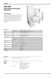
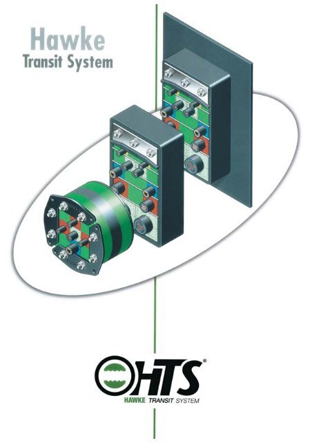
H A W K E R O U N D , M A R I N E A N D C ICable/Pipe Tolerant BlocksMade of zero halogen, intumescent elastomericpolymer. Each block accepts a range of cableand/or pipe diameters enabling the completerange of standard sizes to be covered by asmall number of blocks. <strong>Hawke</strong>´s uniqueinspectable colour coding shows that the tophalf and the bottom half are correctly matched forsizesBlank Filler BlocksMade of the same material as the cable/pipeblocks, filler blocks also come in the samemodular size range. Blank filler blocks are usedto fill up unused space in the frame. The blocksare all marked with their modular size.The Compression <strong>System</strong>1. End PackerThe final element of the frame installation, this isinserted above the compression plate and thebolts tightened to seal the whole frame.2. Compression PlateThis goes on the top row of blocks, to distributethe pressure from the compression tool andcompression system.StayplatesEach evenly packed row of blocks is held by astayplate to assist with assembly, before the nextrow is packed on top.Compression<strong>System</strong>1.End PackerThe <strong>Transit</strong> FrameMade of primed or plated mild steel, stainlesssteel or aluminium, a <strong>Hawke</strong> frame is carefullywelded at the corners and finished to the highestquality. <strong>Hawke</strong> frames can be cast within aconcrete wall, cemented into a wall, bolted to awall or welded or bolted to a metal bulkhead.Open FramesAll frames are also available as open versions,for use where cables are already in position.RadialCompression<strong>System</strong>CompressionRings2.CompressionPlateStainless SteelStayplateColour CodedCable/Pipe Tolerantand Blank Filler Blocks<strong>Hawke</strong> Round <strong>Transit</strong> Frames - HRT<strong>Hawke</strong> round Frames effectively seal cables and pipes passingthrough circular apertures, and pressure seal against fire, water andgas, etc. The seal is formed by tightening the compression bolts whichexpand the system radially, this causes pressure to be exerted againstthe aperture wall and closes down the tolerant blocks<strong>Hawke</strong> Marine <strong>Transit</strong> Frames - HMX<strong>Hawke</strong> Marine Frames are normally welded intodecks and bulkheads in order to provide a secureanchorage for the services which pass through them.HMX frames are made from 60mm x 10mm bar.2www.hawke-hts.com
V I L T R A N S I T S Y S T E M<strong>Hawke</strong><strong>Transit</strong> <strong>System</strong><strong>Transit</strong> Frame MildSteel, Stainless Steelor AluminiumFeatures and Benefits4Selection and Specification8Blocks, Components and Accessories 9<strong>Transit</strong> Frame Dimensions11Civil <strong>Transit</strong> Frame <strong>System</strong>12Civil <strong>Transit</strong> Installation Instructions14Civil Frame Aperture Dimensions16Marine <strong>Transit</strong> Frame <strong>System</strong>s20Marine <strong>Transit</strong> Installation Instructions 22Marine Frame Bulkhead/26Deck Aperture DimensionsCivil and Marine <strong>Transit</strong> Block Installation Guide 27Round <strong>Transit</strong> Frame <strong>System</strong>28Round <strong>Transit</strong> Block InstallationGuide 30<strong>Transit</strong> Assembly Checklist31EMC <strong>Transit</strong> <strong>System</strong>32EMC <strong>Transit</strong> <strong>System</strong> Block Installation Guide 34Design Template35Colour CodedCable/Pipe Tolerantand Blank Filler Blocks<strong>Hawke</strong> Civil <strong>Transit</strong> Frames - HCX<strong>Hawke</strong> Civil Frames are normally cast in concreteor bolted to walls and floors of buildings in orderto provide secure anchorage for any serviceswhich will pass through them. HCX frames aremade from 60mm x 60mm x 6mm angle.www.hawke-hts.comALL COPYRIGHT RESERVED - HAWKE TRANSITSYSTEM 2006THIS DOCUMENT AND ALL COPYRIGHT THEREINIS THE PROPERTY OF: HAWKE TRANSIT SYSTEM.Copyright Condition: This document shall be usedonly for the purpose for which it is provided and noreproduction or publication of the documentmay bemade and no article may be manufactured orassembled in accordance with information containedin the document without prior written consent of theowner.3
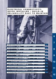
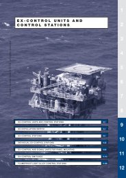
WHAT IS A CABLE TRANSIT SYSTEM?A <strong>Transit</strong> <strong>System</strong> is a means tomaintain the integrity of a firewall,bulkhead or deck through whichcables pipes and other services pass.Can you be suThe transit system will seal againstand exhibit resistance to:• Fire• EMC• Water• Radiation• Gas• Chemicals• Explosion• Ultra Violet light• Smoke• VerminWHERE WOULD YOU USE A TRANSIT SYSTEM?Wherever a wall or bulkhead ispenetrated by cable or pipe theoccupants and integrity of the structureare exposed to risk from hazards suchas fire and smoke, water ingress, toxicgases and attack by vermin.Typical Applications• Water Treatment Plant• Portable Buildings• Chemical Plant• Pharmaceutical Manufacturing• Offshore Accommodation ModulesIncorrect AssemblyWithout colour codingincorrect assembly isimpossible to detect.Typical Applications• Offshore platforms• Oil & Gas Refineries• Floating Production Off-loading Vessel• Nuclear Plant• Ship Building• Computer/Bank Installation• Telecommunications• Jet Engine Test Facilities• National Defence Agencies• Tunnel <strong>System</strong>s4WHY USE A HAWKE TRANSIT SYSTEM?• Increased Safety • Speed of Assembly• Total Inspectability • Cost Effectiveness• Flexibility• Quality and CertificationA <strong>Transit</strong> winstalled- f
e that your <strong>Transit</strong> is correctly installed?Incorrect AssemblyMismatched colour codedblock halves identify areaswhich have been incorrectlyassembledCorrect AssemblyColour coded block halvesprovide visual confirmationof correct assemblywill only perform as well as it has beenfor complete Confidence insist on <strong>Hawke</strong> 5
TOLERANT BLOCK SIZE RANGEThis enables a wide range ofcable or pipe diameters to beaccommodated by a compactrange of tolerant block sizes.<strong>Hawke</strong> tolerant blocks havefive sealing faces that aredisplaced by the sealingprocess. This results in atolerance of up to 4mm forcable diameters.The HawonlyHAWKE COLOEach individual block has a cothat each size and pair of tolcorrectly matched to the cablTOTAL INSPECTABILITYThe <strong>Hawke</strong> colour coded blocksystem provides totalinspectability of the transitinstallation even after assemblyhas been completed.On each of the two exposedblock faces minimum andmaximum diameters are clearlymarked. This indicates thespecific sealing range of theblock size.HAWKE MEASURING TAPEUNIQUE PATENTEDUnique steel insert pins on boCompression <strong>System</strong> ensure tis applied to each installationThe tape enables cablediameters to be accuratelymeasured thus ensuring thatthe correct size of block isselected for the cable diameter.The gauge is wrapped aroundthe cable this then details thecorrect block to select for thatcable together with the colourcoding.6www.hawke-hts.com
ke Cable <strong>Transit</strong> <strong>System</strong> is theTotally Inspectable <strong>System</strong>UR CODINGcolour coded face, this ensuresolerant block halves is alwaysble diameter.COMPRESSION SYSTEMboth sides of the <strong>Hawke</strong> <strong>Transit</strong>that the correct level of compressionon.H A W K E COMPRESSION TOOLWith this tool the system isquickly compressed using aratchet socket operable fromoutside the frame.• Reduces installation timeby up to 50%.• Consistent compressionindependent of the operatorsskill.www.hawke-hts.com7
SELECTION AND SPECIFICATION PROCEDURESelection and SpecificationThere are two main starting points in practice.A. Cables or pipes known, no frame.The ideal way, is when the numbers anddiameters of cable or pipe are known, inadvance of ordering the frame. The procedureshould then follow route A.B. Frame already installed.However, if a transit frame and cables orpipes are already installed, and sealingspecifications are to be determined later,follow route B.No frame, cable or pipe requirements to beadvised in future.If a frame only is required, and all cable/piperequirements are to be advised at a later datein the contract, install as large a frame as ispossible, and fill it with blank blocks.Modular Cable/Pipe Tolerant BlocksIn the Block Selector Table below, the firstcolumn indicates the module size, secondand third columns indicate minimum andmaximum diameters of cable or pipe whichcan be accommodated by each block.Blank Filler blocks are suffixed ‘0’e.g. 15/0 20/0 etc.Code NumbersFor ordering purposes block code numbersare made up from the numbers in columns 1and 2 and are indicated in column 5. i.e. A40 module block capable of accommodatingcable/pipe from 28mm diameter up to 31mmdiameter is denoted 4028. A HF prefixdenotes zero Halogen blocks.NOTE: Two insert blocks are required foreach cable or pipe.Selection and Specification Procedure120 x 60 x 5 Packaging Strip 1120 x 60 x 10 Packaging Strip 1A- Cables/pipes known, no frame B- Frame already installedSTART1. Check (or measure)cable/pipe diameters andnumbers1. Check (or measure) frame(s)size and model number2. Determine the blockrequirements per frame, usingthe design template onPage 352. Check cable or pipenumbers/diameters to gothrough frame (s)3. Determine the frame(s) sizerequired to accommodateblocks, not forgetting to useblank blocks to allow for futureexpansion3. Determine the blockrequirements per frame, usingthe design template onPage 354. Check with builder/construction/engineer/architectthat proposed frame will beaccomodated by building4. Check if the blockarrangements fit in frame(s)provided.YES?5. If YES,complete your order,including all stayplates,compresion blocks and blankblocks, arranged in theappropriate frame size (s),and return to <strong>Hawke</strong> - or your<strong>Hawke</strong> <strong>Transit</strong> Distributor - forchecking and orderconfirmation.NO5.If NO, consult withbuilder/construction/engineer/architect todetermine what frame(s) can beaccommodated, andcables/pipes required, beforere-specifying by startingat 1 above81. Packing strips are supplied as solid strips or with strips precut or scored into individual blocks:TA50 (1 solid block 120x60x5 mm) TA100 (1 solid block 120x60x10 mm)TA50 x 24 (24 pieces 5x60x5 mm) TA100 x 12 (1 block prescored x 12 pieces10x60x10 mm)www.hawke-hts.com
TOLERANT INSERT BLOCKS120 mm90 mm60 mm40 mm30 mm20 mm15 mm<strong>Hawke</strong><strong>Transit</strong> <strong>System</strong>ComponentsCable/Pipe Tolerant BlocksMade of zero halogen, intumescentelastomeric polymer. <strong>Hawke</strong>tolerant blocks are produced in modularform to accommodate cables and/or pipesizes ranging from 3mm to 100mm indiameter.Blank Filler BlocksFiller Blocks are available in the samematerials as the tolerant Blocks.They areused to fill spaces within the frame whichare not required for services, thus allowingspare capacity for future requirements.The cable range is shown on the end of eachblock and indicates the maximum andminimum cable and/or pipe sizes , example18/21 = 18mm min. 21mm max. For easeof reference each block is colour coded.See Block Selector Table on page 8 forordering information.SPECIAL INSERT BLOCKSNon Standard penetrationswhere <strong>Hawke</strong> <strong>Transit</strong> Framesare penetrated by servicesSTANDARD TOLERENT BLOCKthat are shaped anythingother than circular e.g.busbars,earthstraps etc.SPECIAL BLOCKspecial blocks can bemanufactured. <strong>Hawke</strong>manufacture a range ofblocks to suit the mostpopular waveguide sizes.See table opposite. Pleasenote that other sizes can bemade to order. Please contactour Sales Office with details.To ease assembly and guarantee system performance it is a requirement that cablesenter and exit the aperture perpendicular in all axis to the face of the frame.<strong>Hawke</strong> Cable/Pipe Tolerant Blocks<strong>Hawke</strong>’s unique inspectable colourcoded blocks ensure that the topand bottom half of each block hasbeen correctly matched for size.<strong>Hawke</strong> cable/pipe tolerant blockshave been designed with a degreeof flexibility in order toaccommodate variances in cablediameters. Additionally this flexibilityenables each <strong>Hawke</strong> block size toaccept a range of cable or pipediameters.Available in seven sizes from 3mm to100mm in diameter, <strong>Hawke</strong> blocksare marked with minimum andmaximum cable diameters e.g.block size 3018 is marked withsizes 18/21 to signify that it willaccept cable diameters from 18mmup to maximum of 21mm.In practice this means that a smallnumber of blocks canaccommodate the full range ofstandard cable sizes. There is lessinventory to manage and theinstallation and inspectionprocedure is much faster andsimpler than competing systems.www.hawke-hts.com9
COMPRESSION SYSTEM COMPONENTSCompression <strong>System</strong>Order Codes:1642 Complete Compression <strong>System</strong>.1642A Compression Plate only.1642B End Packing assembly only.Compression ToolOrder Code: 981HAWKE TRANSIT ACCESSORIESStayplatesOrder Code: 931 - stainless steel.For pressure application in excess of 3.5 barOrder Code: 931P - stainless steel.Backing plateOrder Code:Size 2: TABP2Size 4: TABP4Size 6: TABP6Size 8: TABP8Polystyrene MouldsOrder CodeSize 2 965/2 Size 6 965/6Size 4 965/4 Size 8 965/8Pulling DeviceOrder Code: 980LubricantOrder code: 967Intumescent Mastic (310ml cartridge)Order code: 966General and Gas applications10www.hawke-hts.com
HAWKE TRANSIT FRAME DIMENSIONS<strong>Hawke</strong> Civil Frame DimensionsThe space available in each frame is divided into two sections; theCompression <strong>System</strong> 40mm x 120mm and the cable/pipe installationarea.60406Civil frames are designated by the letters HCX.The available installation area being indicated by a number added tothis designation, i.e.HCX2Indicating 60mm x 120mmAvailable cable/pipe installation area.240 nom180 nom120 nom60 nomHCX2HCX4HCX6HCX8HCX4Indicating 120mm x 120mmAvailable cable/pipe installation area.606012060HCX6Indicating 180mm x 120mmAvailable cable/pipe installation area.HCX8Indicating 240mm x 120mmAvailable cable/pipe installation area.10 mm10 mm10 mmInternal WidthMultiple Civil FramesOn multiple frames a 10mm wide strip separates each aperture.To obtain the overall frame length add 10mm for every dividingstrip.Overal Width<strong>Hawke</strong> Marine Frame DimensionsThe space available in each frame is divided into two sections; theCompression <strong>System</strong> 40mm x 120mm and the cable/pipe installationarea.Marine frames are designated by the letters HMX.The available installation area being indicated by a number added tothis designation, i.e.:10240 nom40180 nom120 nom60 nomHMX2HMX4HMX6HMX2Indicating 60mm x 120mmAvailable cable/pipe installation area.6010120HMX8HMX4Indicating 120mm x 120mmAvailable cable/pipe installation area.HMX6Indicating 180mm x 120mmAvailable cable/pipe installation area.10 mm10 mm10 mmHMX8Indicating 240mm x 120mmAvailable cable/pipe installation area.Multiple Marine FramesOn multiple frames a 10mm wide strip separates each aperture.To obtain the overall frame length add 10 mm for every dividing strip.HMFX, HMOX,HMEX, HMBX and HMRX are also available asmultiplesInternal WidthOveral WidthNote: All dimensions are in mm and are nominal sizes. Forframe and wall/bulkhead cut out sizes see pages 16 and 18.(civil frames) 24 and 26 (marine frames)www.hawke-hts.com11
H A W K E C I V I L T R A N S I T S YThe HCX FrameFor general use. A compression tool(Order No. 981) is required for use with all‘X’ designated frames.The HCOX FrameA removable end allows the frame to beinstalled around existing cables and pipes.HAWKE TRANSIT LARGE FRAMES300 mm180 mm360 mm240 mm480 mm360 mmOrder Code:964 (2 required)338 mm218 mm180 mm400 mm280 mm240 mm560 mm440 mm360 mmOrder Code:963HCLX180HCLX240HCLX360Order Code:962HCLX Civil Large FramesFor sealing services with an overalldiameter in excess of 100mm. HCLXCivil large framesare available in three sizes eitheras singleunits or as combinations.HCLX Compression <strong>System</strong>Sealing is accomplished by an extendedcompression system available for each sizeof frame. Installation is as the standard unitexcept that force is applied to thecompression plate by a series of compressiontools. Top and bottom for 964.CIVIL FRAMESWeld RemovalWhere aesthetic considerations or specific mounting conditions are a requirement all protruding welds can be ground flush, this processalters standard manufacturing techniques and must be requested when ordering frames, Standard frames should not be modified on siteas this could potentially weaken welding joints.12www.hawke-hts.com
S T E M F R A M E S I Z E S<strong>Hawke</strong>Civil <strong>Transit</strong> <strong>System</strong>CIVIL MULTIPLE FRAMESFrame Materials<strong>Hawke</strong> <strong>Transit</strong> Frames are available in mildsteel, stainless steel and aluminium.For specialist applications frames can bemanufactured to suit customers specificrequirements.Eddy CurrentsWhere there is a possibility of eddy currentsbeing induced into the transit frames causingthe frame to heat up, frames can bemanufactured with non magnetic inserts toreduce the effects.<strong>Hawke</strong> Civil <strong>Transit</strong> Frames• Available in Mild Steel,Stainless Steel andAluminium• Easily installed in concrete/brick constructions withoutthe need for specialisedtools or personnel• Available in single andmultiple aperturecombinations• Unique <strong>Hawke</strong> CompressionTool for ease and speed ofinstallation• Extraction Tool enablesblocks to be removed forcabling modifications ifrequired.www.hawke-hts.com13
C I V I L T R A N S I T S Y S T E M I N S T A LSHUTTERINGPOLYSTYRENEMOULDFRAMECONCRETEFig.1 Fig.2 Fig.31. The frame can be cast directly into a wallor floor.2. The frame may be cast into a concretejacket this method being normally used forbrick and blockwork walls which in turn isfixed into the wall or floor.3. Where transits are for cables of a largediameter, inclined installations of the frameis advisable to reduce the bending radius.9 mm6 mm6 mm9 mmFig.4a Fig.4b Fig.54. Frames can be bolted to floors and wallsin either of the options shown. For boltedinstallations mastic should be insertedbetween the frames flange and the structure.Use <strong>Hawke</strong> mastic Ref. 966.When frames are reverse fixed then 9mmclearance is required to all faces.<strong>Hawke</strong> recommend a minimum of 1 hole percorner set 25mm in from outsideedge of frame with additional fixings at amax of 200mm centres.Size of fixing holes and type of fastener areto be established by the civil contractordependent on size of frame weight andstructure to which it is to be fixed.5. Stayplates and compression plates haveretaining lugs. Clearance for these must beallowed when a frame is cast into a structure.This allowance is 12mm and shouldbe added to the total internal width of theframe to obtain the correct dimensions.<strong>Hawke</strong> Moulds have this allowance built in.(See Page 10).14www.hawke-hts.com
L A T I O N I N S T R U C T I O N S<strong>Hawke</strong>Civil <strong>Transit</strong> <strong>System</strong>12 mm8 mm12 mm6 mm CLEARANCE ALL AROUND FRAME8 mmMASTICFRAMEFig.6Fig.7Mastic ApplicationEach 330ml tube of mastic should besufficient to mount and seal 3 individualframes or a multiple frame of up to 4 apertures1.Prior to application of sealant ensure thatfaces to be sealed are dry and free fromgrease and any loose material, ensure thattransit frame mates up with any fixings/holesalready present checking especially theaperture over which the frame is to bemounted.2.Cut nozzle on mastic to produce a beaddiameter of approximately 8mm.3.Apply two parallel rows of mastic and runa bead of mastic around each hole as shownin Fig.6.Fig.8Lightweight sheet steel backing plates areavailable to be used in conjunction with<strong>Hawke</strong> Civil Frames. These maintain theopenings through the walls and floorsand add to the finished appearance of theinstallation.4.The mastic can be applied to front or rearof the frame dependant on the installation,see Fig.7.5.The frame can now be placed over itsfixings and the fasteners tightened to clampthe frame to the wall. In tightening the fixturesthe mastic should be extruded out of thedecreasing gap between frame and structure,any excess should be removed and disposedof. When tightened up to the requiredamount, the mastic should be faced off to theframe leaving a fillet of mastic around theinternal and external edges of the frame.See Fig.7 above.Fig.9It should be noted that the backing plates donot add to the fire resistance of a transitassembly and should not be used to stop firespread in cavity walls.Backing plates are produced in standardlengths for wall thickness of 60mm to200mm for sizes 2, 4, 6 and 8 framesplus multiples thereof, but specials can bemade.Please state thickness of wall when ordering.Installations and ApplicationsThere are several methods whichcan be used to install <strong>Hawke</strong>Frames, each methodgiving an inspectable professionalfinish to any cable penetration.When fixing frames toconcrete/brick type structures careshould be taken if usingexpanding type fixings as theycould burst into the aperture.For <strong>Hawke</strong> Frames which are castinto a wall or floor it isrecommended that a <strong>Hawke</strong>Polystyrene Mould is used.Frames and moulds requiresupport to ensure that the correctposition is maintainedwhilst the concrete is beingpoured. This may be achieved bynailing through the shuttering intothe mould.<strong>Hawke</strong> Moulds are available tosuit sizes 2, 4, 6 and 8 frameswith 300mm lengths and may becut to suit the depth of the wall orfloor asrequired.www.hawke-hts.com15
C I V I L F R A M E - D I M E N S I O N A L D A T AWhen cast apertures are produced using a <strong>Hawke</strong> preformed polystyrene mould these clearances are built in.When frames are to be turned into a wall add 6mm to each of the dimensions used from the above table.When frames are to be turned into a wall add 6mm to each of the dimensions used from the above table.16www.hawke-hts.com
CIVIL APPROVALS - FIRE<strong>Hawke</strong>Civil <strong>Transit</strong> <strong>System</strong>1. Frame cast into wall or floor.2. For frames bolted to walls or floors, 966<strong>Hawke</strong> intumescent mastic to be used behindthe flange or frame.100 mm150 mmFIRE BATT. DENSITY110 kg/ m 3 MINIMUMSHEREDDED FIRE BATTCivil Approvals - FireIn order to limit the spread of fire,regulations generally demand thatbuildings are divided intocompartments each offering a degreeof fire spread resistance.Fig 3.100 mm100 mm150 mm3. For periods in excess of 120 mins, it may be necessary for frames to be mountedon both sides of the wall or to be insulated as shown. (Contact <strong>Hawke</strong> for latest techinfo).<strong>Hawke</strong> have tested the <strong>Transit</strong>system extensively to National andInternational standards100 mm150 mmFIRE BATT. DENSITY110 kg/ m 3 MINIMUMSHEREDDED FIRE BATT200 nominal4. For certain conditions it may be necessary to restrict the average temperature riseabove ambient on the unexposed face of a compartment wall or floor. Since the metalused in cable construction readily transmits heat, the following installation methods arerecommended to provide compliance for up to 360 minutes. (See Figs. 3 and 4 above).www.hawke-hts.com17
C I V I L T R A N S I T S Y S T E M S - M U L T I P L EMULTIPLE FRAME SIZE CHARTx= number of frames wide. Material thickness is 6 mm externally and 10mm between multiple apertures.Please Note: Frames can be supplied in multiple stacking arrangements.Examples:HCX6 x 3 HCX6 + 6 x 3HCX6 + 6 + 8 x 3Installation Area(see page 11)H = (Height)x = Multiple Width18www.hawke-hts.com
FRAME APPLICATION DATA<strong>Hawke</strong>Civil <strong>Transit</strong> <strong>System</strong>Civil Multiple FramesMultiple frames consist of two ormore apertures arranged eitherhorizontally, vertically or acombination of both.When specifying multiple frames a‘+’ sign signifies that the aperturesare stacked in a vertical row e.g.one on top of the other.An ‘x’ sign means that the aperturesare arranged side by side in anhorizontal row.Examples:HCX6 x 2HCX6 + 6 x 2www.hawke-hts.com19
H A W K E M A R I N E T R A N S I T SThe HMX FrameFor general use. A <strong>Hawke</strong> compression tool(Ref.981) is required for use with all´x`designated frames.The HMFX FrameHas a 60mm wide flange and isavailable in the same materials and finishesas HMX frames. For overall dimensions ofHMFX frames add 120mm (allowance forflange) to those given for standard HMXframes.The HMOX FrameA removable end allows the frame to beinstalled around existing cables and pipes.The HMEX FrameA standard HMX frame extended using awelded collar.For use in corrugated bulkheadsor to fit the frame above deck level. For overalldimensions of HMEX frames add 20mm toexternal measurements of Standard HMXframes.The HMBX FrameFor sealing cable routes in uninsulated HOrated areas or similar applications. Add20mm to external dimensions of standardHMX frames to determine overall width andheight.Also used in 2 hour Jet Fire applicationsThe HMRX FrameFor stressed area applications, end filletpieces with radius corners are added tothe HMX frame.20Marine FramesWeld RemovalWhere aesthetic considerations or specificmounting conditions are a requirement allprotruding welds can be ground flush, thisprocess alters standard manufacturingtechniques and must be requested whenordering frames. Standard frames should notbe modified on site as this could potentiallyweaken welding joints.www.hawke-hts.com
Y S T E M F R A M E S I Z E S<strong>Hawke</strong>Marine <strong>Transit</strong> <strong>System</strong><strong>Hawke</strong> Marine <strong>Transit</strong> Frames• Available in Mild Steel,Stainless Steel and Aluminium• Fully certified for Marineapplications• Easily installed usingstandard welding techniques• Unique <strong>Hawke</strong> CompressionTool for ease and speed ofinstallation•Extraction Tool enablesblocks to be removed forcabling modificationsMARINE MULTIPLE FRAMESFrame Materials<strong>Hawke</strong> <strong>Transit</strong> Frames are available in MildSteel, stainless steel and aluminium.For specialist applications frames can bemanufactured to suit customers specificrequirements.Eddy CurrentsWhere there is a possibility of eddy currentsbeing induced into the transit frames causingthe frame to heat up, frames can bemanufactured with non magnetic inserts toreduce the effects.www.hawke-hts.com21
MARINE FRAME INSTALLATION INSTRUCTIONSInstallation MethodsA choice of <strong>Hawke</strong> Marine Frames isavailable to meet the varied criteria given byeach situation.Examples of frame installations are as follows,each method giving an inspectableprofessional finish to any cable penetration.FRAMEDIMENSION+ 1mm8mm8mmAPERTUREAPERTURE + 20 mmHMXHMFXFor HMX Frames.Bulkhead aperture diameter must be Framesize plus 1mm.See table on page 26.For HMFX Frames.A minimum clearance of 16 mm is requiredto both height and width dimensions as shown.STAY PLATE RETAINING LUGSCONTINUOS WELDCONTINUOS WELDPLAN VIEW<strong>Hawke</strong> Marine Frames should be welded fromboth sides.<strong>Hawke</strong> Marine Frames can be offset from thehorizontal or vertical to reduce the bendingradius on cables passing through them.Note: When installing Marine Frames ensurethe edges of the frame are free of weldwhich could interfere with retaining lugs onstay and compression plates.CONTINUOS WELDHMFXCONTINUOS WELDHMBXCONTINUOS WELDHMEX22www.hawke-hts.com
FRAME WELDING INSTRUCTIONS<strong>Hawke</strong>Marine <strong>Transit</strong> <strong>System</strong>If necessary, to reduce thegap add weld material tothis face (not to the frame)BULKHEAD OR DECK1mm MAXHAWKE TRANSIT FRAMEThe aperture in the bulkhead/deck should be cut out such that the gap surrounding theframe 1mm.If gap is in excess of 1mm weld material may be added to the bulkhead/deck cut faceto reduce the gap. The bulkhead/deck should then be dressed and prepared aspreviously stated.TACK WELDS TO POSITION FRAMEAND HELP PREVENT DISTORTION.FOR MULTIPLE FRAMES 1 TACKWELD PER APERTURE SHOULD BEADDED TOP & BOTTOMWELDS (A) AND (B)FILET WELDS (C) AND (D)Welding Instructions for Mildand Stainless Steel FramesPrior to any welding process the jointand surrounding area should beprepared. The area must be clean,dry and free from any oil, grease,scale or oxide and any otherdebris/contaminates that may affectweld performancee.g. protective coatings andprimers.(B) UNDERSIDE(D) TOPSIDE(A) UNDERSIDE(C) TOPSIDEFRAMES THICKNESS(10 MM FORMARINE FRAMES)STARTz= 1 / 2 T up toz max= 6 mmfor higher values of zmore than one runof filled weld maybe requiredPrior to completing welds on either side of the bulkhead the frame should be tackedinto position as in the sketch above. The tack welds reducing the amount of distortionin the parent metals.The frame must be welded from both sides of the bulkhead.Welding Sequence1st (A) underside, 2nd (B) underside,3rd (C) topside, 4th (D) topsideNote: Allow adequate time for cooling to prescribed levels to prevent cracking betweeneach weld run. Weld runs should not start or stop at a tack weld but should run overa tack.www.hawke-hts.com23
M U L T I P L E F R A M E A P PFRAME SIZE CHART - MULTIPLE WIDTH x SINGLE HEIGHTFRAME SIZE CHART - SINGLE WIDTH x MULTIPLE HEIGHTFRAME SIZE CHART - MULTIPLE WIDTH x SINGLE HEIGHTX= number of frames wide. Material thickness is 10 mmInstallation Area(See page 11)H (height)X = Multiple Width24www.hawke-hts.com
I C A T I O N D A T A<strong>Hawke</strong>Marine <strong>Transit</strong> <strong>System</strong>Marine Multiple FramesMultiple frames consist of two ormore apertures arranged eitherhorizontally, vertically or acombination of both.When specifying multiple frames a‘+’ sign signifies that the aperturesare stacked in a vertical rowe.g. one on top of the other.A ‘x’ sign means that the aperturesare arranged side by side in anhorizontal row.Examples:HMX6 x 2HMX6x3HMX6 +6 x2 HMX6+ 6 x 3www.hawke-hts.com25
MARINE FRAME - DIMENSIONAL DATA26www.hawke-hts.com
TRANSIT INSTALLATION GUIDECivil and Marine<strong>Transit</strong> <strong>System</strong>The following diagrams explain step by step how easy it is toinstall <strong>Hawke</strong> cable/pipe tolerant blocks into Civil or Marine<strong>Transit</strong> frames.<strong>Hawke</strong><strong>Transit</strong> <strong>System</strong>1Draw up a <strong>Hawke</strong> DesignTemplate to determine yourcable/pipe layout.2Make sure the frame is clean,then pull cables or pipes through,placing the largest at the bottom.(Note: Use open ended frame to fit aroundexisting cables/pipes).Lubricate the inside of the3 frame and all the insert blocks.<strong>Hawke</strong> Cable/Pipe/Block Selection Gauge1. Simply wrap the gauge tightly around thecable or pipe from the measurement line.2. Reading along the measurement line willreveal the correct block size for the cable orpipe and identify it by colour code.e.g. 4022 REDWhere there is an overlap between twoblock sizes e.g. 6052 or 9053, either sizecan be selected to best use the availablespace in the transit frame.4Begin packing the frame.A stayplate is insertedbetween each layer of insertblocks.5Insert the compression platebefore the last row of blocksor earlier if required withadditional stayplates.6Pack the last row, insert thecompression tool andtighten until there is sufficientroom to fit the tapered end packers.<strong>Hawke</strong> Compression Tool<strong>Hawke</strong>’s unique Compression Tool.Simplifies the process of compressing tolerantblocks within X type frames and speedsinstallation considerably when compared tocompetitors methods.7Insert two outside packingpieces then remove tool beforefitting centre block.8Tighten the nuts on theendpacking to compress andcomplete the seal. Approximately10mm of thread should protrudeon each bolt.9<strong>Hawke</strong>’s unique colour codingsystem enables the installationto be visually inspected aftercompletion and ensures correctmatching of the block halves.Note:HF600 filler blocks must be installed with the faces moulded with 4 holes in vertical position<strong>Hawke</strong> Cable/Pipe Tolerant Blocks<strong>Hawke</strong>’s unique inspectable colour codedblocks ensure that the top and bottom halfof each block has been correctly matchedfor size.www.hawke-hts.com27
28H A W K E R O U N D T R A N S I T S Y S
T E M F R A M E S I Z E S29
T R A N S I T I N S T A L L A T I O N G U I D ERound <strong>Transit</strong><strong>System</strong>The following diagrams explain step by step how easy it is to install<strong>Hawke</strong> cable/pipe tolerant blocks into Round <strong>Transit</strong> frames.1Draw up a <strong>Hawke</strong> Design Templateto determine your cable/pipe layout.2Measure the inside of pipe oraperture to ensure that it is withinthe tolerance of the Round <strong>Transit</strong>Frame to be used.3Insert the Round <strong>Transit</strong> Frame andopen the two front plate*. Nolubricant should be applied to theaperture or outside of the frame<strong>Hawke</strong> Cable/Pipe/BlockSelection Gauge1. Simply wrap the gauge tightlyaround the cable or pipe from themeasurement line.2. Reading along themeasurement line will reveal thecorrect block size for the cable orpipe and identify it by colourcode.4Pull the cables or pipes throughthe frame. (Note: Use open endedRound <strong>Transit</strong> to fit around existingcables/pipes).Lubricate the inside of the frame5 and each of the insert blocks.6Begin packing the transit framestarting at the bottom andfinishing at the top. Ensure that theblocks are pushed firmly against therear retaining lip.e.g. 4022 REDWhere there is an overlapbetween two block sizes e.g.6052 or 9053, either size can beselected to best use the availablespace in the transit frame.7Slide the two front plates togetherand tighten the nuts 2mmeach time, applying equal pressure toboth plates*. The bolts should betightened until the cables/pipes aresealed. A minimum of 10mm of threadshould protrude on each bolt.8<strong>Hawke</strong>’s unique colour codingsystem enables the installationto be visually inspected aftercompletion and ensures the correctmatching of the block halves.9EXTRACTION OF SYSTEMExtraction is achieved by releasing thecompression, i.e. by reversing steps 5 and6 and screwing M8 bolts(not supplied) intothe threaded holes at each corner of thefront plates. This releases the assemblyfrom the aperture and allows the systemto be disassembled.<strong>Hawke</strong> Cable/Pipe Tolerant Blocks<strong>Hawke</strong>'s unique inspectable colour codedblocks ensure that the top and bottom halfof each block has been correctly matchedfor size.* Note: HRT30, HRT40 and HRT50 front plates are fixed30www.hawke-hts.com
H R T A P P L I C A T I O N S<strong>Hawke</strong>Round <strong>Transit</strong> <strong>System</strong>Cast PipeWelded TubeHRT ApplicationsThe HRT is certified for use in civiland marine installations.The HRT seals cables or pipeswithin cast pipes, welded tubes orcore drilled holes.Core Drilled HoleTRANSIT ASSEMBLY CHECKLIST1.Measure the outside diameter of each cable and ensure that the diameter iswithin the cable range marked on the front of the block that seals each cable.2.Check that all colour codes on the block pairs are matching.3.Check that there are sufficient blocks installed into the frame and that thereare no gaps not sealed by blocks.4.If the transit application is in excess of 3.5 bar high pressure stayplatesshould be used ref. 931p, together with an extra 5mm sealing strip.5.Check the correct amount of compression has been applied to the end packer bolts,10mm of thread on each bolt should be protruding.www.hawke-hts.com31
T H E H A W K E E M C T R A N S I T S Y S T E MStainless SteelStayplatesInstalled to anchor insertand filler blocks into theframe and ease assembly.They also increase theconductance throughoutthe frame.The Compression<strong>System</strong>Seals the penetration whenall the services have beeninstalled. The 3 partendpacker transmits anevenly distributed pressureonto the compression plateand ensures an effective sealaround the cables.The materials:Packing blocks - intumescentflame retardant elastomercoated with a silver loadedspray and wrapped withcopper strip for effectiveshielding. End packer plates- Electro zinc plated steel orstainless steel.Compression plates-Electrozinc plated cast steel.Tolerant insert andfiller blocks.Made from an intumescentflame retardant elastomercoated on all surfaces witha silver loaded spraywhich is highly conductiveand provides the excellentshielding ability. Inaddition, a layer ofadhesive copper strip isapplied around the blockto aid conductivity. <strong>Hawke</strong>blocks can accommodatecables ranging from 3mmto 100mmdiameter, and includetolerant blocks which allowfor variations in cablediameters by using fiveindividual sealing faceswhich take up the cablevariations within their ownindividual areas.Note:Block module size should besuffixed E (e.g. 3012/E). Theadhesive EMI Shielding Tape isavailable in the followinglengths:Size 18 = 16.5mSize 36 = 32.9mAdhesive Copper StripProvided to build up to theinsertblocks and the strippedcable. The cable outersheath should be strippedto a maximum width of2cm to expose the cablescreen. All the cablesrequire the removal of theouter sheath toachieve contact betweenthe cable screen and theblocks. The copper EMIshielding tape withconductive adhesive iswrapped around thecable screen until thenominal outside diameterof the cable is achieved.This is important to ensurecomplete conductance ofthe electromagneticpulses/fields in the innerwalls of the steel frameagainst earth.The FrameThe electro zinc plated steelor stainless steel frame isattached to the structure andforms thesurround for the penetration.32PERFECTION INVITES CLOSER INSPECTION
F O R C A B L E S A N D P I P E STesting ProceduresHunting Communication Technology Limited, Electromagnetic Assessment Group, werereferred to as specialists with extensive testing facilities. A series of three specified tests wererecommended to assess the transit performance and provide design data.<strong>Hawke</strong>EMC <strong>Transit</strong> <strong>System</strong>for Cables and PipesFig 1.– Test for Shielding Effectiveness(No. U2501/TR/6660)The aim of the test was to measure theshielding effectiveness of the <strong>Transit</strong> by amethod generally in accordance with MILSTD 285. The testing was actually performedusing a swept measurement techniqueemploying a spectrum analyser with trackinggenerator to 1GHz and a Scalar networkanalyser from 1GHz to 10GHz.Conclusion:The <strong>Transit</strong> showed good shielding results being inexcess of 70dB over much of the tested frequencyrange.Fig 2.–Test for Current Leakage(No. U2501/TR/6661)The test was designed to assess theconductivity of the <strong>Transit</strong> when used with avariety of cables. As there is not a standardspecification for this assessment, a test methodwas formulated which measured theconductivity in terms of current leakage fromthe cable shield to earth within a frequencyrange of 100KHz to 500MHz.Conclusion:Based upon the worst case data obtained, itwas observed that the current leakage wasbetter than 35dB over the frequency range100KHz to 500MHz. Infact, for most of thefrequency range the current leakage was atleast 50db.Fig 3.– Test for transient (pulse) conductivity(No. 2501/TR/6662)The tests involved assessing the transientconductivity of the <strong>Transit</strong> when used with avariety of cables. The method used measuredthe conductivity in terms of current leakagefrom the cable shield to earth under thetransient conditions. The test was based uponDEF STAN 59-41 using transients consisting ofa 100KHz damped sinusoid applied by acurrent transformer.Conclusion:The current leakage under transient conditionsfor the cable set ups tested show a minimuminsertion loss of 30dB.Fig 1.– Test for Shielding Effectiveness(No. U2501/TR/6660)Fig 2.–Test for Current Leakage(No. U2501/TR/6661)Fig 3.– Test for transient (pulse)conductivity(No. 2501/TR/6662)Fig 3.– Test for transient (pulse)conductivity(No. 2501/TR/6662)The Hazards of RFI/EMPThe need to protect sensitive electronicequipment against extraneouselectromagnetic and radio frequencyradiation is an increasing and criticalfactor in the design of equipment andinstallations.A major concern is to ensure the integrityof operation of the equipment such ascomputers, signalling control andcommunication systems by effectivesealing and low resistance earthcontinuity bonding at cable and pipeentry points of a low ‘noise’ environment.Electromagnetic Compatibility (EMC).This is the term used to express theability of electronic equipment or systemsto operate satisfactorily in a givenenvironment without responding toelectrical noise or emitting unwantednoise.The <strong>Hawke</strong> EMC Cable <strong>Transit</strong> <strong>System</strong>.<strong>Hawke</strong>’s system has been furtherdeveloped from the highly successfulCivil and Marine <strong>Transit</strong>s which areequally suitable for cables or pipes.Electromagnetic compatibility isachieved by reducing theElectromagnetic interference (EMI) to alevel which in most applications willnot disrupt the proper operation of theelectronics.www.hawke-hts.com33
EMC TRANSIT SYSTEM INSTALL ATION GUIDEEMC <strong>Transit</strong><strong>System</strong>The following diagrams explain step by step how easy it is to installEMC <strong>Hawke</strong> cable/pipe tolerant blocks into EMC <strong>Transit</strong> frames.1Draw up a <strong>Hawke</strong> Design Templateto determine your cable/pipelayout.2Make sure the frame is clean, thenpull cables or pipes through,placingthe largest at the bottom. (Note: Useopen ended frame to fit around existingcables/pipes).3Mark each cable in the centre ofthe frame and 7-8mm either side ofthis point.4Cut and remove cable sheathbetween two outside marks, toexpose the cables conductive screen.5 6Using copper tape provided tightlywrap around the exposed screenuntil the cable outer diameter isregained. Repeat steps 3, 4 & 5 for allcables.Very slightly lubricate the insertblocks taking care not tocontaminate the copper tape on blockor cable.7Ensure when fitting cables intoblocks that the copper tapes onblock and cable align.8Begin packing the frame.A stayplate is inserted betweeneach layer of insert blocks.9Insert the compression platebefore the last row of blocksor earlier if required with additionalstayplates.Pack the last row, insert10the compression tool and 1112tighten until there is sufficient roomto fit the tapered end packers.Insert two outside packing piecesthen remove tool before fittingcentre block.Tighten the nuts on theendpacking to compress andcomplete the seal. Approximately 10mmof thread should protrude on each bolt.If possible after completion the assembly should be tested for conductivity34www.hawke-hts.com
F O R C A B L E S A N D P I P E S<strong>Hawke</strong><strong>Transit</strong> <strong>System</strong>MARINE AND CIVIL FRAME SIZESROUND FRAME SIZESwww.hawke-hts.com35
HAWKE TRANSIT SYSTEM - HTSHead OfficePaseo del Niño 4, Nave B-239300 Torrelavega. SpainTel.: +34 942 89 00 52Fax: + 34 942 88 30 58email: sales@hawke-hts.comAvailable from your local approved stockistU.K. Sales OfficeP.O. Box 271WILMSLOWSK9 3WS United KingdomTel.: + 44(0) 1625 252162Fax: + 44(0) 1625 251062sales@hawke-hts.comwww.hawke-hts.comOctober 2007