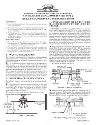
Type 8 Models - Hunter Fan Company
Type 8 Models - Hunter Fan Company
Type 8 Models - Hunter Fan Company
- No tags were found...

Create successful ePaper yourself
Turn your PDF publications into a flip-book with our unique Google optimized e-Paper software.
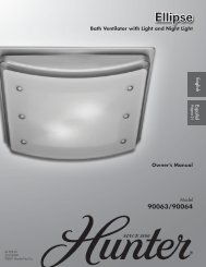
For Your Records andWarranty AssistanceFor reference, also attach your receipt or a copyof your receipt to the manual.__________________________________________Model Name<strong>Type</strong> 8 <strong>Models</strong>Owner’s Guide and Installation Manual__________________________________________Model No.__________________________________________Catalog No.__________________________________________Date Purchased__________________________________________Where PurchasedEnglish EspañolForm# 41968-0120081002©2008 <strong>Hunter</strong> <strong>Fan</strong> Co.
WelcomeYour new <strong>Hunter</strong>® ceiling fan is an addition to your home or office thatwill provide comfort and performance for many years. This installationand operation manual gives you complete instructions for installingand operating your fan.We are proud of our work. We appreciate the opportunity to supplyyou with the best ceiling fan available anywhere in the world.Table Of Contents1 • Getting Ready ......................42 • Installing the Ceiling Plate ..........53 • Assembling and Hanging the <strong>Fan</strong> ...64 • Wiring the <strong>Fan</strong> .....................75 • Installing the Canopy and Canopy TrimRing ..............................86 • Assembling the Blades. .............97 • Installing the Switch Housing .......108 • Operating and Cleaning Your Ceiling<strong>Fan</strong> ...............................129 • Troubleshooting. ...................13Before installing your fan, for your records and warranty assistance,record information from the carton and <strong>Hunter</strong> nameplate label(located on the top of the fan motor housing).Cautions and Warnings• READ THIS ENTIRE MANUAL CAREFULLY BEFORE BEGINNINGINSTALLATION. SAVE THESE INSTRUCTIONS.• Use only <strong>Hunter</strong> replacement parts.• To reduce the risk of personal injury, attach the fan directly to thesupport structure of the building according to these instructions,and use only the hardware supplied.• To avoid possible electrical shock, before installing your fan,disconnect the power by turning off the circuit breakers to theoutlet box and associated wall switch location. If you cannot lockthe circuit breakers in the off position, securely fasten a prominentwarning device, such as a tag, to the service panel.• All wiring must be in accordance with national and local electricalcodes and ANSI/NFPA 70. If you are unfamiliar with wiring, use aqualified electrician.• To reduce the risk of personal injury, do not bend the bladeattachment system when installing, balancing, or cleaning the fan.Never insert foreign objects between rotating fan blades.• To reduce the risk of fire, electrical shock, or motor damage, do notuse a solid-state speed control with this fan. Use only <strong>Hunter</strong> speedcontrols.© 2008 <strong>Hunter</strong> <strong>Fan</strong> <strong>Company</strong>241968-01 • 10/02/08 • <strong>Hunter</strong> <strong>Fan</strong> <strong>Company</strong>
Installer’s Choice and Optional AccessoriesStandardMountingStyleSupport BraceCeilingOutlet BoxStandard Mounting hangs from theceiling by a downrod (included).Understanding Mounting and Installer’s Choice®<strong>Hunter</strong>’s patented 3-position mounting system provides you maximuminstallation flexibility and ease. You can install your <strong>Hunter</strong> fan in oneof three ways, depending on ceiling height and your preference: LowProfile, Standard, or Angled mounting. The steps in this manual includeinstructions for all three Installer’s Choice mounting methods.Considering Optional AccessoriesConsider using <strong>Hunter</strong>’s optional accessories, including a wall-mountedor remote speed control. To install and use the accessories, followthe instructions included with each product. For quiet and optimumperformance of your <strong>Hunter</strong> fan, use only <strong>Hunter</strong> speed controls.Support BraceCeilingOutlet BoxFor ceilings higher than 8 feet, you can purchase<strong>Hunter</strong> extension downrods. All <strong>Hunter</strong> fans usesturdy 3/4” diameter pipe to assure stability andwobble-free performance.AngledMountingStyle128Low ProfileMountingStyleSupport BraceCeilingOutlet BoxCAUTION: Toreduce the risk ofpersonal injury, attachthe fan directly to thesupport structure ofthe building accordingto these instructions,and use only thehardware supplied.Angled Mounting recommended for avaulted or angled ceilingLow Profile Mounting fits close to theceiling, recommended for ceilings lessthan 8 feet high341968-01 • 10/02/08 • <strong>Hunter</strong> <strong>Fan</strong> <strong>Company</strong>
To install a ceiling fan, be sure you can do the following:• Locate the ceiling joist or other suitable support in ceiling.• Drill holes for and install wood screws.• Identify and connect electrical wires.• Lift 40 pounds.1 • Getting ReadyIf you need help installing the fan, your <strong>Hunter</strong> fan dealer can directyou to a licensed installer or electrician.Gathering the ToolsYou will need the following tools for installing the fan:• Electric drill with 9/64” bit• Standard screwdriver (magnetic tip recommended)• Phillips-head screwdriver (magnetic tip recommended)• Wrench or pliers• Ladder (height dependent upon installation site)Checking Your <strong>Fan</strong> PartsCarefully unpack your fan to avoid damage to the fan parts. Refer tothe included Parts Guide. Check for any shipping damage to the motoror fan blades. If any parts are missing or damaged, contact your <strong>Hunter</strong>dealer or call <strong>Hunter</strong> Technical Support Department at 888-830-1326.Installing Multiple <strong>Fan</strong>s?If you are installing more thanone fan, keep the fan blades andblade irons (if applicable) in sets,as they were shipped.Preparing the <strong>Fan</strong> SiteBefore you begin installing the fan, follow all the instructions inthe pullout sheet called “Preparing the <strong>Fan</strong> Site.” Proper ceiling fanlocation and attachment to the building structure are essential forsafety, reliable operation, maximum efficiency, and energy savings.441968-01 • 10/02/08 • <strong>Hunter</strong> <strong>Fan</strong> <strong>Company</strong>
2 • Installing the Ceiling PlateCAUTION: To avoid possible electrical shock, before installing your fan,disconnect the power by turning off the circuit breakers to the outlet boxand associated wall switch location. If you cannot lock the circuit breakersin the off position, securely fasten a prominent warning device, such as atag, to the service panel.2-1. Drill two pilot holes into the wood support structure through theoutermost holes in the outlet box. The pilot holes should be 9/64”in diameter.2-2. Your fan comes with four neoprene noise isolators (“Isolators”).Position the isolators between the ceiling plate and ceiling byinserting the raised areas on each isolator into the holes in theceiling plate.2-3. Thread the lead wires from the outlet box down through the holein the middle of the ceiling plate.2-4. Align the slotted holes in the ceiling plate with the pilot holes youdrilled in the wood support structure. For proper alignment useslotted holes directly across from each other.Note: The isolators should be flush against the ceiling.2-5. Place a flat washer on each of the two 3” wood screws and passthe screws through the slotted holes in the ceiling plate into thepilot holes you drilled.Tighten the screws into the 9/64” pilot holes; do not use lubricantson the screws. Do not over tighten.IsolatorCeilingPlateStep 2-2Steps 2-3 – 2-5Flat Washer3” Wood ScrewFor Angled Ceilings: Be sure toorient the ceiling plate so that thearrows printed on the ceiling plate arepointing toward the ceiling peak.541968-01 • 10/02/08 • <strong>Hunter</strong> <strong>Fan</strong> <strong>Company</strong>
3 • Assembling and Hanging the <strong>Fan</strong>WARNING: <strong>Fan</strong> may fall if not assembled as directed in theseinstallation instructions.3-1. Unbundle the wires from the fan.For Standard or Angled mounting:3-2. To assemble fan to hang down from a flat or angled ceiling, insertthe downrod through the canopy and canopy trim ring. Feed thewires from the fan through the downrod.3-3. Loosen the square head setscrew on the adapter to install the pipeand ball assembly. Note: When the pipe and ball assembly is fullyinstalled, 2-3 threads on the pipe will still be visible; this is normal.Securely retighten the setscrew with a wrench or pliers. Skip toStep 3-7.CAUTION: The adapter has a special coating on the threads. Donot remove this coating; the coating prevents the downrod fromunscrewing. Once assembled, do not remove the downrod.For Low Profile mounting:Note: For low profile mounting, the downrod is replaced with the lowprofile washer.3-4. Remove the setscrew from the adapter.3-5. Place the low profile washer (lip up) into the canopy. Be sure thegreen ground wire is pointing up toward the ceiling.3-6. Align the holes in the washer with the holes in the adapter.Assemble securely with three low profile screws.3-7. Raise the fan and place the hook on the ceiling plate through theU-shaped hole in the rim.Step 3-7U-shapedHoleSteps 3-2 – 3-3Steps 3-5 – 3-6Low Profile ScrewDownrodCanopyCanopyTrim RingSetscrewLow Profile Washer641968-01 • 10/02/08 • <strong>Hunter</strong> <strong>Fan</strong> <strong>Company</strong>
4 • Wiring the <strong>Fan</strong>fsdfsdfAll wiring must be in accordance with national and local electricalcodes and ANSI/NFPA 70. If you are unfamiliar with wiring, use aqualified electrician.Wall switches are not included. Select an acceptable general-use switchin accordance with national and local electrical codes.4-1. Before attempting installation, make sure the power is still off.4-2. To connect the wires, hold the bare metal leads together and placea wire connector over them, then twist clockwise until tight. Forall these connections use the wire connectors provided.4-3. Connect the bare or green ground wire (grounded) from theceiling to the green ground wire (grounded) from the ceiling plateand the green ground wire from the fan.4-4. Connect the white wire (ungrounded) from the ceiling to thewhite wire (ungrounded) from the fan.4-5. Connect the remaining wires as follows:Dual Switch Wiring:• The black wire (ungrounded) from the ceiling to the black wire(ungrounded) from the fan• The black/white wire (ungrounded) from the fan to the wire(ungrounded) for the wall switchSingle Switch Wiring:• The black wire (ungrounded) from the ceiling to the black(ungrounded) and the black/white wire (ungrounded) fromthe fanCAUTION: Be sure no bare wire or wire strands are visible aftermaking connections.4-6. Turn the splices upward and push them carefully back through theceiling plate into the outlet box.4-7. Spread the wires apart, with the grounded wires on one side ofthe outlet box and the ungrounded wires on the other side of theoutlet box.WireConnectorDual Switch WiringSingle Switch Wiring741968-01 • 10/02/08 • <strong>Hunter</strong> <strong>Fan</strong> <strong>Company</strong>
5 • Installing the Canopy and Canopy Trim Ring5-1. Holding the canopy, raise the fan off the hook.5-2. Align the slots in the canopy with the tabs on the ceiling plate.5-3. Raise the canopy over the ceiling plate. Rotate the canopyclockwise until the tabs on the ceiling plate totally engage withthe slots in the canopy.5-4. Partially install the three canopy screws into the canopy one at atime. Once all three screws are in, tighten them.5-5. Using both hands, push the canopy trim ring up to the top of thecanopy. The canopy trim ring will snap and lock into place.Step 5-2CanopyCeiling PlateCanopy TrimRingShould you need to remove the canopytrim ring, follow these steps:1. Locate the tab indicators, smallbumps on top of tabs.2. Press firmly on opposite sides of thering toward the canopy. The tabs willflex out releasing the trim ring fromthe canopy.Steps 5-4 – 5-5Step 5-3CanopyScrew841968-01 • 10/02/08 • <strong>Hunter</strong> <strong>Fan</strong> <strong>Company</strong>
6 • Assembling the Blades<strong>Hunter</strong> fans use several styles of fan blade irons (brackets that hold theblade to the fan).6-1. Your fan may include blade grommets. If your fan has grommets,insert them by hand into the holes on the blades.6-2. Attach each blade to a blade iron using three blade assemblyscrews. If you used grommets, the blades may appear slightly looseafter screws are tightened. This is normal.6-3. Remove the blade mounting screws and rubber shipping bumpersfrom the motor. Note: Some blade mounting screws are installedin the motor to secure shipping blocks.6-4. For each blade, insert one blade mounting screw through theblade iron, and attach lightly to the fan. Insert the second blademounting screw, then securely tighten both mounting screws.Step 6-1 (Detail)GrommetUse with grommetBlade AssemblyScrewsSteps 6-1 – 6-2Use without grommetBladeMountingScrewStep 6-4941968-01 • 10/02/08 • <strong>Hunter</strong> <strong>Fan</strong> <strong>Company</strong>
7 • Installing the Switch HousingSide HolesSteps 7-1 – 7-27-1. Connect the upper plug connector from the motor to the lowerplug connector in the switch housing assembly.Note: Both plug connectors are polarized and will only fit togetherone way. Make sure the connectors are properly aligned beforeconnecting them. Incorrect connection could cause improperoperation and damage to the product.7-2. To attach the switch housing, thread the screws through the sideholes of the mounting plate and tighten them securely.Note: If you are installing the light fixture, proceed to 8 • Installing theLight Fixture. If you are not installing the light fixture, proceed withsteps 7-3 – 7-4 to complete the installation.7-3. Thread the finial with rod (from the sack parts) through the switchhousing cap and into the switch housing.7-4. Tighten the finial.SwitchHousingFinialSwitchHousingCapSteps 7-3 – 7-41041968-01 • 10/02/08 • <strong>Hunter</strong> <strong>Fan</strong> <strong>Company</strong>
8 • Installing the Light Fixture8-1. Plug in the light fixture and turn the finial until it is tight.8-2. Place each shade on a socket.8-3. Install 4 candelabra bulbs (40 Watt maximum).Note: In compliance with US federal energy regulations, thisceiling fan contains a device that restricts the light kit to amaximum of 190 Watts. Exceeding that limit or the markedlimit on this product may result in fire hazard or improperoperation.FinialStep 8-1Steps 8-2 – 8-31141968-01 • 10/02/08 • <strong>Hunter</strong> <strong>Fan</strong> <strong>Company</strong>
9 • Operating and Cleaning Your Ceiling <strong>Fan</strong>9-1. Turn on electrical power to the fan.9-2. The fan pull chain controls power to the fan. The pull chain hasfour settings in sequence: High, Medium, Low, and Off.• Pull the chain slowly to change settings.• Release slowly to prevent the chain from recoiling into theblades.• The chain uses a breakaway connector that separates if thechain is jerked. If this happens, simply reinsert the chain intothe connector.9-3. The light pull chain controls the power to the light fixture. Thechain has two settings: ON and OFF.9-4. Ceiling fans work best by blowing air downward (counterclockwiseblade rotation) in warm weather to cool the room with a directbreeze. In winter, having the fan draw air upward (clockwise bladerotation) will distribute the warmer air trapped at the ceilingaround the room without causing a draft.9-5. For cleaning finishes, use a soft brush or lint-free cloth to preventscratching. A vacuum cleaner brush nozzle can remove heavierdust. Remove surface smudges or accumulated dirt and dust usinga mild detergent and a slightly dampened cloth. You may usean artistic agent, but never abrasive cleaning agents as they willdamage the finish.9-6. Clean wood finish blades with a furniture polishing cloth.Occasionally, apply a light coat of furniture polish for addedprotection and beauty. Clean painted and high-gloss blades in thesame manner as the fan finish.In warm weather, usedownward air flow patternIn cold weather, use upwardair flow patternTo Change Airflow DirectionTurn the fan off and let it come to a completestop. Slide the reversing switch on the fan to theopposite position. Restart fan.ReversingSwitch1241968-01 • 10/02/08 • <strong>Hunter</strong> <strong>Fan</strong> <strong>Company</strong>
10 • TroubleshootingProblem: Nothing happens; fan does not move.1. Turn power on, replace fuse, or reset breaker.2. Loosen canopy, check all connections according to the wiring thefan section.3. Check the plug connection in the switch housing.4. Push motor reversing switch firmly left or right to ensure that theswitch is engaged.5. Pull the pull chain to ensure it is on.6. Remove the shipping bumpers.Problem: Noisy operation.1. Tighten the blade assembly screws and blade iron armature screwsuntil snug.2. Check to see if the blade is cracked. If so, replace all the blades.Problem: Excessive wobbling.1. If your fan wobbles when operating, use the enclosed balancing kitand instructions to balance the fan.2. Tighten all blade iron screws.3. Turn power off, support fan very carefully, and check that thehanger ball is properly seated.Problem: Lights dim when turned on or do not turn on1. Check to make sure the wattage and type of light bulbs installedmatch the specifications on the light socket.If you need parts or service assistance, please call888‐830‐1326 or visit us at our Web site athttp://www.hunterfan.com.<strong>Hunter</strong> <strong>Fan</strong> <strong>Company</strong>2500 Frisco AvenueMemphis, Tennessee 381141341968-01 • 10/02/08 • <strong>Hunter</strong> <strong>Fan</strong> <strong>Company</strong>