infcp-b-qs - Newport
infcp-b-qs - Newport
infcp-b-qs - Newport
- No tags were found...

You also want an ePaper? Increase the reach of your titles
YUMPU automatically turns print PDFs into web optimized ePapers that Google loves.
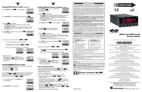
Scaling With Known Loads (Continued)6. Press MENU to store IN!1. The unit displays:7. Press /TARE. The unit displays the last setting for RD!1.5 68. Change RD!1 as necessary:• Press /TARE to scroll to the digit(s) you want to change(it flashes on the display).• Press /MAX to change the value of the flashing digit. Valuescan range from 0 to 9. For the first digit, you can also enter aminus sign (–) or –1.9. Press MENU to store the value shown for RD!1.The unit displays:To identify the maximum known load (IN!2 and RD!2):1. Apply the maximum known load (100%).2. Repeat steps 4–9 above, for IN!2 and RD!2.Once you've completed all steps, the unit displays:To begin operation:Reinitialize the unit (press RESET twice orpress MENU until RST flashes on the display).When a numeric reading appears, the unit isoperational.Scaling Without Known LoadsFor 4-20 mA sensors, the values for the minimum and maximuminput loads are always as follows:• Minimum load (IN!1) — 2000• Maximum load (IN!2) — 9999.If your installation uses a different sensor type, you must calculatethe values for IN!1 and IN!2 before proceeding with the stepsbelow. Use the formula provided in the Operator's Manual.To define the minimum load (IN!1 and RD!1):1. If it's not already shown, press MENU untilthe unit displays:2. Press /TARE. The unit displays:Scaling Without Known Loads (Continued)3. Press /TARE again. The unit displays thelast setting for IN!1.(The first digit flashes.)4. Change IN!1 as necessary:• Press /MAX to set or change the digit's current value. Continue topress /MAX until the meter displays the desired value for theflashing digit. Values can range from 0 to 9. For the first digit, you canalso enter a minus sign (–) or –1.• Press /TARE to scroll to the digit(s) you want to change.5. Press MENU to store IN!1. The unit displays:6. Press /TARE. The unit displays the lastsetting for RD!1. (The first digit flashes.)7. Change RD!1 as necessary:• Press /MAX until the meter displays the desired value for theflashing digit. Values can range from 0 to 9. For the first digit, youcan also enter a minus sign (–) or –1.• Press /TARE to scroll to the digit(s) you want to change.8. Press MENU to store the value shown for RD!1.The unit displays:To define the maximum load (IN!2 and RD!2):1. Repeat steps 3–8 above, entering the values for IN!2and RD!2.2. Once you've completed all steps, the unit displays:To begin operation:Reinitialize the unit (press RESET twice orpress MENU until RST flashes on thedisplay). When a numeric reading appears,the unit is operational.Determining Reading OffsetThe run mode reading for meters scaled without known loads mayreflect an offset. For example, say you set RD!1 to 0 and RD!2 to100, but when the minimum load is applied, a negative value of –1.5displays on the front panel.To correct the reading offset:1. With zero load applied, note the reading on the display.2. Subtract that amount from the RD!1 and RD!2 values youoriginally entered.In the example, the offset would be –1.5. If RD!1 is to read 0 inRun Mode, it must be reentered as 1.5. RD!2 must likewise bereentered as 101.5 if the meter is to read 100 when themaximum load is applied.3. Repeat the steps for "Scaling Without Known Loads," but whenthe values for IN!1 and IN!2 display, do not change them.Instead, press MENU to move to the prompts for RD!1 and RD!2and make the necessary changes.4. Reinitialize the unit and resume operation.WARRANTY/DISCLAIMERNEWPORT Electronics, Inc. warrants this unit to be free of defects in materials and workmanshipfor a period of one (1) year from the date of purchase. In addition to NEWPORT’s standardwarranty period, NEWPORT Electronics will extend the warranty period for four (4) additionalyears if the warranty card enclosed with each instrument is returned to NEWPORT.If the unit malfunctions, it must be returned to the factory for evaluation. NEWPORT’s CustomerService Department will issue an Authorized Return (AR) number immediately upon phone orwritten request. Upon examination by NEWPORT, if the unit is found to be defective, it will berepaired or replaced at no charge. NEWPORT’s WARRANTY does not apply to defects resultingfrom any action of the purchaser, including but not limited to mishandling, improper interfacing,operation outside of design limits, improper repair, or unauthorized modification. ThisWARRANTY is VOID if the unit shows evidence of having been tampered with or shows evidenceof having been damaged as a result of excessive corrosion; or current, heat, moisture orvibration; improper specification; misapplication; misuse or other operating conditions outside ofNEWPORT’s control. Components which wear are not warranted, including but not limited tocontact points, fuses, and triacs.NEWPORT is pleased to offer suggestions on the use of its various products. However,NEWPORT neither assumes responsibility for any omissions or errors nor assumesliability for any damages that result from the use of its products in accordance withinformation provided by NEWPORT, either verbal or written. NEWPORT warrants only thatthe parts manufactured by it will be as specified and free of defects.NEWPORT MAKES NO OTHER WARRANTIES OR REPRESENTATIONS OF ANY KINDWHATSOEVER, EXPRESS OR IMPLIED, EXCEPT THAT OF TITLE, AND ALL IMPLIEDWARRANTIES INCLUDING ANY WARRANTY OF MERCHANTABILITY AND FITNESS FOR APARTICULAR PURPOSE ARE HEREBY DISCLAIMED.LIMITATION OF LIABILITY: The remedies of purchaser set forth herein are exclusive, andthe total liability of NEWPORT with respect to this order, whether based on contract,warranty, negligence, indemnification, strict liability or otherwise, shall not exceed thepurchase price of the component upon which liability is based. In no event shallNEWPORT be liable for consequential, incidental or special damages.CONDITIONS: Equipment sold by NEWPORT is not intended to be used, nor shall it be used:(1) as a "Basic Component" under 10 CFR 21 (NRC), used in or with any nuclear installation oractivity; or (2) in medical applications or used on humans. Should any Product(s) be used in orwith any nuclear installation or activity, medical application, or used on humans, or misused inany way, NEWPORT assumes no responsibility as set forth in our basicWARRANTY/DISCLAIMER language, and, additionally purchaser will indemnify NEWPORT andhold NEWPORT harmless from any liability or damage whatsoever arising out of the use of theProduct(s) in such a manner.RETURN REQUEST/INQUIRIESDirect all warranty and repair requests/inquiries to the NEWPORT Customer Service Department.BEFORE RETURNING ANY PRODUCT(S) TO NEWPORT, PURCHASER MUST OBTAIN ANAUTHORIZED RETURN (AR) NUMBER FROM NEWPORT’S CUSTOMER SERVICEDEPARTMENT (IN ORDER TO AVOID PROCESSING DELAYS). The assigned AR numbershould then be marked on the outside of the return package and on any correspondence.The purchaser is responsible for shipping charges, freight, insurance and proper packaging toprevent breakage in transit.FOR WARRANTY RETURNS, pleaseFOR NON-WARRANTY REPAIRS,have the following information available please consult NEWPORT for currentBEFORE contacting NEWPORT:repair charges. Have the followinginformationavailable BEFORE contactingNEWPORT:1. Purchase Order number under which 1. Purchase Order number to cover thethe product was PURCHASED,COST the repair,2. Model and serial number of the 2. Model and serial number of product,product under warranty, andand3. Repair instructions and/or specific 3. Repair instructions and/or specificproblems relative to the product.problems relative to the product.NEWPORT’s policy is to make running changes, not model changes, whenever an improvementis possible. This affords our customers the latest in technology and engineering.NEWPORT is a registered trademark of NEWPORT Electronics, Inc.© Copyright 2006 NEWPORT Electronics, Inc. All rights reserved.This document may not be copied, photocopied, reproduced, translated, or reduced to anyelectronic medium or machine-readable form, in whole or in part, without the prior written consentof NEWPORT Electronics, Inc.PATENT NOTICE: This product is covered by one or more of the following patents: U.S. Pat. No.Des. 336,895; 5,274,577; 6,243,021 / Canada 2052599; 2052600 / Italy 1249456; 1250938 /France Brevet No. 91 12756 / Spain 2039150; 2048066 / UK Patent No. GB2 249 837; GB2 248954 / Germany DE 41 34398 C2.Other U.S. and International patents pending or applied for.WARNING: These products are not designed for use in, and should not be used for, patientconnectedapplications.This device is marked with the international caution symbol. It is important to read theSetup Guide before installing or commissioning this device, as the guide containsimportant information relating to safety and EMC.It is the policy of NEWPORT to comply with all worldwide safety and EMC/EMI regulations that apply.NEWPORT is constantly pursuing certification of its products to the European New Approach Directives.NEWPORT will add the CE mark to every appropriate device upon certification.The information contained in this document is believed to be correct, but NEWPORT Electronics, Inc.accepts no liability for any errors it contains, and reserves the right to alter specifications withoutnotice.TRADEMARK NOTICE:NEWPORT® NEWPORT®, , , , ,and the “Meter Bezel Design” are trademarks of NEWPORT Electronics, Inc.MQS3597/N/1006INFCP and INFCP-xxxBProcess MeterFor immediate technical or application assistance please call:<strong>Newport</strong> Electronics, Inc.2229 South Yale Street • Santa Ana, CA • 92704 • U.S.A.TEL: (714) 540-4914 • FAX: (203) 968-7311Toll Free: 1-800-639-7678 • www.newportUS.com • e-mail:info@newportUS.comISO 9001 Certified<strong>Newport</strong> Technologies, Inc.976 Bergar • Laval (Quebec) • H7L 5A1 • CanadaTEL: (514) 335-3183 • FAX: (514) 856-6886Toll Free: 1-800-639-7678 • www.newport.ca • e-mail:info@newport.ca<strong>Newport</strong> Electronics, Ltd.One Omega Drive • River Bend Technology CentreNorthbank, Irlam • Manchester M44 5BD • United KingdomTel: +44 161 777 6611 • FAX: +44 161 777 6622Toll Free: 0800 488 488 • www.newportuk.co.uk • e-mail:sales@newportuk.co.uk<strong>Newport</strong> Electronics spol s.r.o.Frystatska 184, 733 01 Karviná • Czech RepublicTEL: +420 59 6311899 • FAX: +420 59 6311114Toll Free: 0800-1-66342 • www.newport.cz • e-mail: info@newport.cz<strong>Newport</strong> Electronics GmbHDaimlerstrasse 26 • D-75392 Deckenpfronn • GermanyTEL: 49 7056 9398-0 • FAX: 49 7056 9398-29Toll Free: 0800 / 6397678 • www.newport.de • e-mail: sales@newport.deMexico and Latin AmericaFAX: 001 (203) 359-7807En Español: 001 (203) 359-7803
START HERE2 3 4Using This Quick Start ManualUse this Quick Start Manual to set up your Process Meter and beginoperation. Information is provided on how to:• Connect ac power • Set basic options for operationConnect the sensor • Scale the meter.Features with are for the “B” version which has three-colorprogrammable “Big” LED display - All segment characters shown are forthe “B” version.IMPORTANT: For complete information on all setup options, pleaserefer to the Operator’s Manual.This Quick Start Manual includes specific configurationparameters for transducers with an output range of 4–20 mAand 24 V excitation. Other sensor types may require differentparameters or additional ones. When this is the case, we referyou to the Operator's Manual for detailed instructions.Safety ConsiderationThis device is marked with the international Caution symbol.The instrument is a panel mount device protected in accordance with EN61010-1:2001, electrical safety requirements for electrical equipment formeasurement, control and laboratory. Remember that the unit has nopower-on switch. Building installation should include a switch or circuitbreakerthat must be compliant to IEC 947-1 and 947-3.SAFETY:• Do not exceed voltage rating on the label located on the top of the instrumenthousing.• Always disconnect power before changing signal and power connections.• Do not use this instrument on a work bench without its case for safetyreasons.• Do not operate this instrument in flammable or explosive atmospheres.• Do not expose this instrument to rain or moisture.EMC:• Whenever EMC is an issue, always use shielded cables.• Never run signal and power wires in the same conduit.• Use signal wire connections with twisted-pair cables.• Install Ferrite Bead(s) on signal wire close to the instrument if EMC problemspersist.Mount the Unit1. Cut a panel opening using the dimensionsshown to the right.2. Position the unit in the opening, makingsure the front bezel is flush with thepanel.3. Install retaining clips on both sides ofthe meter and tighten against the panel.WiringWarning: Do not connect AC power to your device until youhave completed all input and output connections. This devicemust only be installed by a specially trained electrician withcorresponding qualifications. Failure to follow all instructionsand warnings may result in injury!1. Remove the panel at the back of the unit.2. Locate the TB1 connector.3. Insert the correct wire in each terminal as shown in the following figureand tighten the lockdown screws.4. Tug gently on the wires to verify the connections.External Fuse Required:Time-delay, UL 248-14 listed Time-lag, IEC 127-3 recognized175 mA (115 Vac line) 125 mA (115 Vac line)80 mA (230 Vac line) 63 mA (230 Vac line)Wiring (continued)When using DC power, do not use internal excitation or IsolatedAnalog Output for high color brightness. For low or mediumbrightness, internal excitation is limited to 24 V @ 25 mA; 5 V, 10V, 12 V @ 35 mA.In order to maintain the same degree of protection as the AC units,always use a Safety Agency Approval DC source with the sameOvervoltage Category and Pollution Degree.DC Powered Unit ConnectionsConnect the Sensor1. Locate the TB2 connector on the rear of the unit.2. Attach the sensor wires and tighten the lockdown screws.The diagram below shows the wiring for 4–20 mA sensors with internalexcitation.Refer to the Operator’s Manual for setup requirements for othersensor types.DEVICECurrent Input Connections (4–20 mA)with Internal Excitation3. Tug gently on the wires to verify the connections.4. Replace the panel at the back of the unit.Using the Configuration MenuTo configure the meter, you use the buttons on the front panel.To:Take This Action:Display thePress the MENU button. The first functionConfiguration Menu on the menu, INPT, displays.Select a submenu 1. Press MENU until the function youfunctionwant is shown.2. Press /TARE.The information you can change flashes.Select a value 1. Press /MAX to display the optionfor that submenuyou want.function 2. Press MENU to store it.STRD quickly flashes, indicating thatthe selection has been stored in memory.Then the next menu function displays.Go back to previous Press RESET once.menu functionExit thePress RESET twice. The unit displaysConfigurationMenuRST as it reinitializes. When a numericvalue displays, the unit is in run mode.(Optionally, you can press MENU tomove through all the menu functionsuntil the unit reinitializes.)Using the Configuration Menu (continued)MENU SUBMENU /TAREDESCRIPTIONINPT 100M, ±50M, !10V, !±5V, 0-20* InputDEC.P FFFF*, F.FFF, FF.FF, FFF.F Decimal PointRD.S.O IN!1, RD!1, IN!2, RD!2Scale and OffsetRD.CF R.1=T*, R.1=N Reading ConfigurationR.2=0, R.2=1, R.2=2, R.2=3, R.2=4*R.3=F*, R.3=UCOLR GRN, RED, AMBR Display ColorS1.CF S.1=A*, S.1=B Setpoint 1 ConfigurationS.2=U*, S.2=LS2.CF S.1=A*, S.1=B Setpoint 2 ConfigurationS.2=U*, S.2=LS1.DB 0003* Setpoint 1, DeadbandS2.DB 0003* Setpoint 2, DeadbandOT.CF O.1=E *, 0.1=D Analog OutputO.2=C *, 0.2=VConfigurationO.3=A *, 0.3=PO.4=D , 0.4=RO.5=F , 0.5=HP.BND 0000 shown if 0.3 = P Proportional BandM.RST 0000 shown if 0.3 = P Manual ResetOT.S.O RD!1, OUT1, RD!2, OUT2 Output Scale & OffsetLK.CF RS=E *, RS=D Lockout ConfigurationSP=E *, SP=DL3=0*, L3=1BRIT M.BrT, .BrT, H.BrT Display Brightness* Factory Default SettingsTo Set the Input Type1. Press MENU until the unit displays:2. Press /TARE. The unit displays:3. For this application you want 0-20. If 0-20 is not displayed,press /MAX until it appears. Other choices are 100M, 50M,10V and 5V.Refer to the Operator's Manual for more information onchanging ranges.4. Press MENU to select the sensor shown. The meter displays thenext menu item. If you changed input type, the meter displays:To Set the Decimal Point1. If it's not already shown, press MENU until theunit displays:2. Press /TARE. The unit displays:To Set the Decimal Point (continued)3. Press /MAX to move the decimal point to thedesired location. The choices are FFFF,F.FFF, FF.FF, and FFF.F.4. Press MENU to select the decimal point position shown. Theunit displays:To Scale the MeterYou can scale the meter in one of two ways:1. With a known load — This method uses input (load) informationsent from another device such as a scale or a simulator forvoltage or current.2. Without a known load — This involves calculating the loadbased on transducer specifications and manually entering it tothe meter.For both methods, you must first identify the minimum input loadIN!1 and the corresponding display reading you want RD!1. Thenyou identify the maximum input load IN!2 and its correspondingdisplay reading RD!2.The decimal point is for display purposes only — you set itwhere you want it to display for your application.When entering IN!1 and IN!2 values, ignore any decimalpoint on the display. However, you must enter RD!1 andRD!2 values with the decimal point in the desired position.Scaling With Known LoadsTo identify the minimum known load (IN!1 and RD!1 ):1. If it's not already shown, press MENUuntil the unit displays:2. Apply the minimum known load (0%).3. Press /TARE. The unit displays:4. Press /TARE again. The unit displays thelast setting for IN!1.5. Press /TARE again. The unit displays theactual reading being received from thesending device.AC Powered Unit Connections