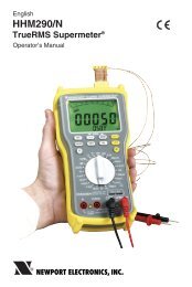
INFP - INFINITY Process Panel Meter DC Current ... - NEWPORT
INFP - INFINITY Process Panel Meter DC Current ... - NEWPORT
INFP - INFINITY Process Panel Meter DC Current ... - NEWPORT
- No tags were found...

You also want an ePaper? Increase the reach of your titles
YUMPU automatically turns print PDFs into web optimized ePapers that Google loves.
Additional products from<strong>NEWPORT</strong> Electronics,Inc.CountersFrequency <strong>Meter</strong>sPID ControllersClock/TimersPrinters<strong>Process</strong> <strong>Meter</strong>sOn/OffControllersRecordersRelativeHumidityTransmittersThermocouplesThermistorsWireRate <strong>Meter</strong>sTimersTotalizersStrain Gauge<strong>Meter</strong>sVoltmetersMultimetersSoldering IronTesterspH penspH ControllerspH ElectrodesRTDsThermowellsFlow SensorsFor Immediate AssistanceIn the U.S.A. and Canada: 1-800-<strong>NEWPORT</strong> ®In Mexico: (95) 800-<strong>NEWPORT</strong> SMOr call your local <strong>NEWPORT</strong> Office.<strong>NEWPORT</strong>net SM On-Line Servicehttp://www.newportUS.comInternet e-mailinfo@newportUS.comIt is the policy of <strong>NEWPORT</strong> to comply with all worldwide safety and EMC/EMI regulations that apply.<strong>NEWPORT</strong> is constantly pursuing certification of its products to the European New Approach Directives.<strong>NEWPORT</strong> will add the CE mark to every appropriate device upon certification.The information contained in this document is believed to be correct but <strong>NEWPORT</strong> Electronics, Inc. accepts no liability for any errors itcontains, and reserves the right to alter specifications without notice.WARNING: These products are not designed for use in, and should not be used for, patient connected applications.PATENT NOTICE: The “<strong>Meter</strong> Case Bezel Design” is a trademark of <strong>NEWPORT</strong> Electronics, Inc., registered in the U.S.PATENT NOTICE: This product is covered by one or more of the following patents: U.S. Pat. No. Des. 336,895; 5,274,577 / Canada2052599; 2052600 / Italy 1249456; 1250938 / France Brevet No. 91 12756 / Spain 2039150; 2048066 / UK Patent No. GB2 249 837;GB2 248 954 / Germany DE 41 34398 C2. Other International Patents Pending.This device is marked with the international hazard symbol. It is important to read the Setup Guide before installing orcommissioning this device as it contains important information relating to safety and EMC.
Table of ContentsSECTION 15 RS-232 OR RS-485 OPTION BOARD15.1 Features Overview ................................................................11315.2 Front-<strong>Panel</strong> Pushbutton Configuration..................................115SECTION 16 EXTERNAL CONTROL LINES16.1 TARE (PIN 1) ........................................................................11616.2 PEAK (PIN 2) ........................................................................11616.3 VALLEY (PIN 3).....................................................................11716.4 SWLIN2 (PIN 4) ....................................................................11716.5 PEAK & VALLEY or EXTERNAL RESET (PIN 5)..................11716.6 PUSH TO CAL (PIN 6) ..........................................................11716.7Digital Return (PIN 7) ............................................................11716.8 +5 V (PIN 8) ..........................................................................11716.9 Display Hold (PIN 9)..............................................................11716.10 LOCKOUT EEPROM (and ‘MENU’ BUTTON) (PIN 10)........11716.11 Print Command and/or Reset of Alarms (PIN 11) .................11716.12 Nonstandard RX (PIN 12) and Nonstandard TX (PIN 13).....11816.13 PUSH TO CAL (PIN 14) ........................................................11816.14 +V EXT (PIN 15) ...................................................................11816.15 SP1 (PIN 16) .........................................................................11816.16 SP2 (PIN 17) .........................................................................11816.17AL1 (PIN 18) .........................................................................11816.18 AL2 (PIN 19) .........................................................................11816.19 RTN EXT (PIN 20).................................................................118SECTION 17 DISPLAY MESSAGES AND TROUBLESHOOTING GUIDE17.1 Error Mode Message.............................................................11917.1.1 Flashing “999999” (Numerical Overflow) ..............................11917.1.2 Flashing “ERR O1” (Offset Overflow)....................................11917.1.3 Flashing “ERR O2” (Setpoint Overflow) ................................11917.1.4 “NOSTOR” & “STORED(Programming Entries In EEPROM) .....................................11917.1.5 Flashing “+OVLD” (Positive Input Overload).........................11917.1.6 Flashing “+OPEN” (Open Sensor Indication)........................11917.1.7 Flashing “-OPEN” (Open Sensor Indication).........................12017.1.8 Flashing “I OVSC” (Input Overscale) ....................................12017.1.9 Flashing “R OVSC” (Reading Overscale) .............................12017.1.10 Flashing “CB OVF” (Count By Overflow) ..............................12017.1.11 Flashing “UOM.OVF” (Unit Of Measure Overflow) ...............12017.2 Troubleshooting Guide..........................................................120SECTION 18 SPECIFICATIONS18.1 <strong>Current</strong> Input.........................................................................12318.2 Voltage Input.........................................................................12318.3 Potentiometer Input...............................................................12318.4 General .................................................................................123iv
Table of ContentsSECTION 19 FACTORY PRESET VALUES ..............................................128SECTION 20 RECORD YOUR SETUP VALUES.......................................131v
FiguresFigure 4-1 Front Detail ............................................................................7Figure 4-2A AC Power - Connector Label for Rear Connectors .............10Figure 4-2B <strong>DC</strong> Power - Connector Label for Rear Connectors..............11Figure 4-3 Rear View with the optional 4-relay output boardand a serial communications board installed.......................12Figure 4-4 Rear View with the optional BCD output boardand a serial communications output board installed............12Figure 5-1 <strong>Meter</strong> Exploded View...........................................................14Figure 5-2 Board Assembly Removing/Installing Detail ........................15Figure 5-3 Transformer Jumpers ..........................................................17Figure 5-4 Optional Printed Circuit Board Locations.............................18Figure 5-5 Signal Input Board ...............................................................19Figure 5-6 ac-Powered Main Board ......................................................20Figure 5-7dc-Powered Main Board ......................................................20Figure 5-8 Relay Option Board .............................................................21Figure 5-9 4-Relay Option Board ..........................................................21Figure 5-10 Analog Output Option Board ...............................................22Figure 5-11 RS-232 Option Board ..........................................................22Figure 5-12 RS-485 Option Board ..........................................................22Figure 5-13 BCD Option Board...............................................................23Figure 5-14 <strong>Panel</strong> Mounting Assembly ...................................................24Figure 6-1 S1 and S2 Jumper Locations on Signal Input Board...........26Figure 6-2 ac Main Board Jumper Positions S3 and S4 .......................29Figure 6-3 dc Main Board Jumper Positions S3 and S4 .......................30Figure 7-1 <strong>Current</strong> Input Without Sensor Excitation .............................31Figure 7-2 <strong>Current</strong> Input With Sensor Excitation ..................................31Figure 7-3 Voltage Input Without Sensor Excitation .............................32Figure 7-4 3-Wire Voltage Input With Sensor Excitation.......................32Figure 7-5 4-Wire Voltage Input With Sensor Excitation.......................32Figure 7-6 Potentiometer Connections with Internal Power Supplyand Ratio Measurement. .....................................................33Figure 7-7 Potentiometer Connections With External Power Supplyand Ratio Measurement (Remove jumper S2-T).................33Figure 7-8 AC Connector Wiring at P1 .................................................34vi
FiguresFigure 7-9 <strong>DC</strong> Connector Wiring at P1 .................................................34Figure 8-1 Factory Calculated Scale Factors........................................48Figure 10-1 Setpoints 1 & 2 Action .........................................................90Figure 10-2 Setpoints 3 & 4 Action .........................................................90Figure 10-3 <strong>Process</strong> Deviation................................................................92Figure 10-4 High Deviation for both Active Above and Active Below ......92Figure 10-5 Low Deviation for both Active Above and Active Below.......93Figure 10-6 Band Deviation for both Active Above and Active Below .....93Figure 10-7AL CNF Hysteresis ..............................................................94Figure 12-1 Analog Option Board and Connection Diagram at P5. ......101Figure 12-2 Isolated Analog Output Board Wiring Connections. ..........103Figure 13-1 BCD 40-Pin Cable Connector (P8)....................................104Figure 13-2 BCD Option Board.............................................................105Figure 13-3 Address Programming Chart for 4 -line Address ...............108Figure 14-1 Dual Relay .........................................................................110Figure 14-2 4 Relay Board Jumpers and Plugs.....................................111Figure 14-3 Dual Relay Output Board Wiring Connections...................112Figure 14-4 4 Relay Output Board Wiring Connections ........................112Figure 15-1 RS-232/RS-485 Option Board and Pin Designations ........114Figure 15-2a Older RS-232 Option Board and Pin Designations............114Figure 15-2b Older RS-485 Option Board and Pin Designations............114Figure 16-1 Connector Label Detail ......................................................116Figure 16-2 Connection of External Power for Setpoint Transistors .....118Figure 18-1 <strong>Meter</strong> Housing and <strong>Panel</strong> Cutout. .....................................132Table 4-1 Rear Connector Descriptions ..............................................12Table 14-1 Dual Relay Board Jumpers................................................110Table 14-2 4 Relay Board Jumpers......................................................111Table 14-3 Pin assignments for the P6, P7 and P18 plugs..................112vii
Notes, Warnings, and CautionsInformation that is especially important to note is identified by these labels:• NOTE• WARNING• CAUTION• IMPORTANTNote ☞NOTE: provides you with information that is important to successfully setupand use the Programmable Digital <strong>Meter</strong>.CAUTION or WARNING: tells you about the risk of electric shock.CAUTION, WARNING or IMPORTANT: tells you of circumstances orpractices that can effect the meter's functionality and must refer toaccompanying documents.viii
Introduction 11.1 DESCRIPTION1.2 FEATURESThis <strong>Process</strong> meter is part of a complete line of process indicators/controllers, offering exceptional performance.The process meter is front panel programmable to accept 0-20 and 4-20mAdc current inputs, unipolar and bipolar <strong>DC</strong> voltage inputs andpotentiometer inputs. The meter will accept inputs from most of the processsensors in use today such as transmitters, pressure transducers, and potentiometers.Configuring the meter is accomplished through the 5 front panel buttons. Ifthe RS-232 or RS-485 communication option is installed, the user mayremotely set the display parameters.Options for the meter include analog and BCD outputs, relay outputs, andRS-232 or RS-485 communications.The following is a list of features of the meter.• 6-digit LED display in red or green• 0.005% accuracy of reading• 12 <strong>DC</strong> input ranges: 0-100 mV, 0-1 V, 0-5 V, 1-5 V, 0-10 V, 0-100 V,±50 mV, ±500 mV, ±5 V, ±50 V, 0-20 mA, or 4-20 mA• 10 or 24 V dc sensor excitation• Peak & Valley detection and memory• External Tare• Up to 13 readings per second• 4 isolated open collector outputs(standard) and optional isolated relay orisolated BCD and isolated analog outputs• Optional isolated RS-232 or RS-485 communications• NEMA 4 Front <strong>Panel</strong>/IP65• Non-volatile memory without battery back-up• 115 Vac, 50/60 Hz, 230 Vac, 50/60 Hz power supply• Optional 10-32 Vdc power supply1
1 Introduction1.3 AVAILABLE MODELSThe following models and options are available. Optional boards are eitherinstalled at the time of purchase, or available as separate items and installedby the user after purchase.MAIN ASSEMBLIESMODELNUMBER<strong>INFP</strong>0<strong>INFP</strong>1<strong>INFP</strong>2<strong>INFP</strong>3<strong>INFP</strong>4<strong>INFP</strong>5DESCRIPTIONRed LEDs, 115 V ac, 50/60HzRed LEDs, 230 V ac, 50/60HzGreen LED’s, 115 V ac, 50/60 HzGreen LED’s, 230 V ac, 50/60HzRed LEDs, 10-32 V dcGreen LED’s, 10-32 V dcNote ☞NOTE: The following options are available installed at the time of purchaseor as separate items installed by the user after purchase:Analog Output Board, BCD Output Board, Relay Output Board, RS-232Communications Board, and RS-485 Communications Board.CONTROL/BCD OUTPUT OPTIONSMODELNUMBER DESCRIPTION“0” Standard four open-collector outputs are standard“1” (BCD1) Isolated BCD Output Board“2” (REL1) Dual 7A Form-C Relays“4” (REL4) Dual 7A & Dual 1A Form-C Relays (not available with dc unit).Note ☞NOTE: Choose only one Control/BCD output option per meter. A 40-pinmating connector is included with the BCD option.ANALOG OUTPUT2MODELNUMBER DESCRIPTION“0” None“1” (ANO2) Isolated configurable analog (4-20 mA, 0-1, 0-5, 1-5,0-10 V dc, 0-20 mA) output
Introduction 1SERIAL COMMUNICATIONS OPTIONMODELNUMBER DESCRIPTION“1” (RS20)* Isolated RS-232 Communications“2” (RS40)** Isolated RS-485 CommunicationsNote ☞NOTE: Choose only one option per meter. Both computer communicationscomes with 6 ft. communications cable with phone plug termination.Free configuration software is available from www.newportUS.com/softwareor on the CD-ROM enclosed with your shipment.* Recommend purchase of 9SC2 or 25SC2 (see OPTIONS below)** Recommend purchase of 9SC4 or 25SC4 (see OPTIONS below)OPTIONSMODELNUMBERFSH5H6BL9SC29SC425SC225SC4RP18RP28RP38SP1SPC4SPC18TP1DESCRIPTIONCustom Calibration/configuration50 Hz line frequency (Requires”FS”)60 Hz line frequency (Requires”FS”)Blank lens9-pin Serial Connector for RS-2329-pin Serial Connector for RS-48525-pin Serial Connector for RS-23225-pin Serial Connector for RS-48519” Rack panel for one (1) meter19” Rack panel for two (2) meters19” Rack panel for three (3) metersSplit connector for RS-485 network1/8 DIN NEMA 4 heavy duty cover with thumb screws1/8 DIN NEMA 4 Splash Proof lens cover with spring clipTrimplate adapter3
2 UnpackingUnpack all items and make sure that every item on the packing list ispresent. The items you should receive are listed below. If something ismissing, use the phone number for the Customer Service Departmentnearest you.Also, inspect the shipping container and enclosed equipment for any signs ofdamage. Take particular note of any evidence of rough handling in transit.Immediately report any damage to the shipping agent.Note ☞NOTE: The shipping agent will not honor any claims unless all shippingmaterial is saved for their examination. After examining and removingcontents, save all packing material and containers in the event thatreshipment is required.When you ordered your process meter, you will receive the following items inthe shipping box:QTY DESCRIPTION ILLUSTRATION1 Basic <strong>Meter</strong> in a MountingSleeve with Gasket1 Front-<strong>Panel</strong> Button CoverAC Power Connector(orange - P1)123P1LN2 Input Connectors(gray - P3 and P9)1234
Unpacking 21 Rear ProtectiveCover with Screw1 20-Socket RibbonConnector(P2 Connector)2 <strong>Panel</strong>-MountingGaskets (1 Spare)1 <strong>Process</strong> Owner’s Guide1 Quick Start ManualOther items may also be in the box depending on the options ordered. Referto specific options described previously.5
3 Safety Considerations63.1 SAFETY CONSIDERATIONSThis device is marked with the international caution symbol. It is important to readthis manual before installing or commissioning this device as it contains importantinformation relating to Safety and EMC (Electromagnetic Compatibility).Unpacking & InspectionUnpack the instrument and inspect for obvious shipping damage. Do not attempt toNote ☞ operate the unit if damage is found.This instrument is a panel mount device protected in accordance with Class I of EN61010 (115/230 AC power connections), Class III for the <strong>DC</strong> power option (10-32Vdc).Installation of this instrument should be done by Qualified personnel. In order to ensuresafe operation, the following instructions should be followed.This instrument has no power-on switch. An external switch or circuit-breaker shall be includedin the building installation as a disconnecting device. It shall be marked to indicate this function,and it shall be in close proximity to the equipment within easy reach of the operator. The switch orcircuit-breaker shall not interrupt the Protective Conductor (Earth wire), and it shall meet therelevant requirements of IEC 947–1 and IEC 947-3 (International Electrotechnical Commission).The switch shall not be incorporated in the mains supply cord.Furthermore, to provide protection against excessive energy being drawn from themains supply in case of a fault in the equipment, an overcurrent protection device shallbe installed.• The Protective Conductor must be connected for safety reasons. Check that thepower cable has the proper Earth wire, and it is properly connected. It is not safeto operate this unit without the Protective Conductor Terminal connected.Conductor Terminal connected.Note ☞• Do not exceed voltage rating on the label located on the top of the instrumenthousing.• Always disconnect power before changing signal and power connections.• Do not use this instrument on a work bench without its case for safety reasons.• Do not operate this instrument in flammable or explosive atmospheres.• Do not expose this instrument to rain or moisture.• Unit mounting should allow for adequate ventilation to ensure instrument doesnot exceed operating temperature rating.• Use electrical wires with adequate size to handle mechanical strain and powerrequirements. Install without exposing bare wire outside the connector tominimize electrical shock hazards.EMC Considerations• Whenever EMC is an issue, always use shielded cables.• Never run signal and power wires in the same conduit.• Use signal wire connections with twisted-pair cables.• Install Ferrite Bead(s) on signal wires close to the instrument if EMC problemspersist.Failure to follow all instructions and warnings may result in injury!
Parts of the <strong>Meter</strong> 44.1 FRONT OF THE METERThe following is a brief description of each part of the front of the meter.121 2 2 2 3 2 4Figure 4-1. Front DetailITEM DESCRIPTION1 –.8.8.8.8.8. or 8.8.8.8.8.8.6-digit, 14 segment, alphanumeric 0.54” high LED display withprogrammable decimal point.2 SETPOINT LEDSETPTS MAX MIN MENU RESET3 4 5 6 7These LEDs, labeled 1 through 4, display the status of setpoints1, 2, 3 (Alarm 1), and 4 (Alarm 2).3 SETPTS BUTTONThis button functions only in the run mode. When theSetpoint/Alarm features are unlocked, pressing this buttonsequentially recalls the previous setpoint settings to the display.After the ‘MIN’ and ‘MAX’ buttons are used to alter thosevalues as desired, pressing the ‘SETPTS’ button, again, storesthese new values.Unless the ‘SETPTS’ button is pressed, each of the four setpointvalues is displayed for approximately 10 seconds after the lastpress of the ‘SETPTS’ button. Holding the ‘SETPTS’ buttondepressed stalls this automatic sequence, retaining the mostrecent setpoint number on the display.7
4 Parts of the <strong>Meter</strong>ITEM DESCRIPTION4 /MAX BUTTONDuring run mode, pressing this button displays the “HI RDG”(peak reading) value that has occurred up to the moment the‘MAX’ button is pressed. This peak reading flashes, todistinguish its value from the current readings. Since this is adynamic peak reading, the value will change if the valueincreases while reviewing it.To return to display of the current readings without resetting thepeak-value memory to zero (0), press the ‘MAX’ button onceagain.To reset the peak-value memory (start a new peak determiningperiod), press the ‘RESET’ button once.During the configuration mode, the ‘MAX’ button is used tochange the numerical value of the flashing digit displayed. Forsubmenu items, such as “L1C.1=0”, pressing the ‘MAX’ buttontoggles the choice from “0” to “1”.The meter allows rapid changes of a displayed numerical valueby making “0” the first value to occur when the ‘MAX’ button ispressed. After that, the numbers increase to “9” and then rollover to “0” again. A negative (“–”) symbol may be displayed inthe most significant digit (i.e. the digit at the far left such asshown here “–.8.8.8.8.8.”)In the SETPT (SETPOINT) mode (SP1, SP2, etc), pressing the‘MAX’ button causes the flashing digit to increment by 1 from 0to 9.5 /MIN BUTTONDuring run mode, pressing the ‘MIN’ button recalls the “LORDG” (valley reading) measured since the last press of the‘RESET’ button. This lowest value flashes, to distinguish it fromthe current process display. Since this is a dynamic valleyreading, the value will change if the value decreases whilereviewing it.8
Parts of the <strong>Meter</strong> 4ITEMDESCRIPTIONTo return to the actual process display, without resetting the lowvaluememory, press the ‘MIN’ button once again.To reset the memory for current-value readings (start a newobservation period), press the ‘RESET’ button once and themeter will return to the run mode.In the configuration mode, once in a submenu (like input type)the ‘MIN’ button allows you scroll through the available choicessuch as, 0-20 mA or 4-20 mA, etc.In the SETPT mode, the ‘MIN’ button advances the flashing digitto the right.6 MENU BUTTONIn the run mode, this button terminates the measurementprocess and allows you to enter the configuration mode,advancing through the configuration menus.In the configuration mode, this button will store changes in thenon-volatile memory at the same time advancing the display tothe next menu item.7 RESET BUTTONIn the run mode, pressing the ‘RESET’ button once erases thememories of peak (“HI RDG”), valley (“LO RDG”), and ALARMlatches. The display then returns to the run mode.WARNING: Pressing the ‘RESET’ button two (2) times willresult in a hard reset of the meter. This will clear the Peak &Valley, Alarm latches and meter reading and immediately begina new measurement.In the configuration mode, pressing the ‘RESET’ button once,displays the previous selection. For example, if you were in “INCNF” then pressed the ‘RESET’ button once, the display willthen show “RD.SC.OF”. Press the ‘RESET’ button two times toreturn to the run mode.9
4 Parts of the <strong>Meter</strong>4.2 REAR OF THE METERThe following is a brief description of each part of the rear of the meter. Thelabel on the top of the mounting sleeve (not the case) identifies the locationof the connectors found at the rear of the meter. Figure 4-2A & figure 4-2Bshows this label.P2 / CABLE CONNECTORTARE(T) 1VALLEY(V) 3PEAK/VALLEY OR EXT RESET 5DIG RTN 7DISPLAY HOLD 910RESET ALARMS AND/OR 911PRINT COMMAND 11NONSTANDARD TX 13+V EXT 15SP2 17AL2 19P4 / RS2326 N/C5 COMM RTN4 RX3 TX2 RTS1 N/CP4 / RS4856 N/C5 B,-RX4 A, +RX3 COMM RTN2 B, -TX/RX1 A, +TX/RXP6 / RELAYP7 / RELAY1 2 3 1 2 3NO1CM1NC1LINE LNUETRAL NGND1 P6 1 P7P1NO2CM2NC2P8 / BCD (see manual for pinout)P1 / ACPOWER1P212 PEAK(P)4 SWLIN26 PUSH TO CAL8 +5VLOCKOUT EEPROM &MENU PUSH BUTTON12 NONSTANDARD RX14 PUSH TO CAL16 SP118 AL120 RTN EXTP5 / ANALOG OUT1 RETURN2 4-20MA3 0-10VFigure 4-2A. AC Power - Connector Label for Rear ConnectorsP4P5* NOT AVAILBALEWITH=<strong>DC</strong> POWER* P18 / 4RELAY1 2 3 4 5 6NO3CM3NC3NO4CM4NC4P9&P3 / SIGNAL INP8 or P161 +EP9 +S1 - SP3- E+R- RCONNECT TO LOW VOLTAGE LIMITED ENERGY CIRCUITRY ONLY.119110
Parts of the <strong>Meter</strong> 4P2 / CABLE CONNECTORTARE(T) 1VALLEY(V) 3PEAK/VALLEY OR EXT RESET 5DIG RTN 7DISPLAY HOLD 910RESET ALARMS AND/OR 911PRINT COMMAND 11NONSTANDARD TX 13+V EXT 15SP2 17AL2 19P4 / RS2326 N/C5 COMM RTN4 RX3 TX2 RTS1 N/CP4 / RS4856 N/C5 B,-RX4 A, +RX3 COMM RTN2 B, -TX/RX1 A, +TX/RXP6 / RELAYP7 / RELAY1 2 3 1 2 3NO1CM1NC11 P6 1 P7P1NO2CM2NC2P8 / BCD (see manual for pinout)P1 / <strong>DC</strong>POWERN/C+1P21P42 PEAK(P)4 SWLIN26 PUSH TO CAL8 +5VLOCKOUT EEPROM &MENU PUSH BUTTON12 NONSTANDARD RX14 PUSH TO CAL16 SP118 AL120 RTN EXTP5 / ANALOG OUT1 RETURN2 4-20MA3 0-10VFigure 4-2B. <strong>DC</strong> Power - Connector Label for Rear ConnectorsP5* NOT AVAILBALEWITH=<strong>DC</strong> POWER* P18 / 4RELAY1 2 3 4 5 6NO3CM3NC3NO4CM4NC4P9&P3 / SIGNAL INP8 or P161 +EP9 +S1 - SP3- E+R- RCONNECT TO LOW VOLTAGE LIMITED ENERGY CIRCUITRY ONLY.119111
5 Setup5.2.3 Printed Circuit Board(s) InstallationTo install optional printed circuit board(s):1. “Reveal the Main Board” (refer to Section 5.2, Disassembly).2. Using Figure 5-4 as a reference, insert option board(s) into thecorresponding slot(s) on the main board. Each circuit board iskeyed to fit in it’s own position.P10 (4 RELAY BOARD ONLY)RETAINER(ALWAYS USEDEXCEPT FORBCD OR 4 RELAYOPTION)P12P20P14J20 BCD BOARD OR 4 RELAY BOARDINTERCONNECT BOARD(PART OF BCD ASSY)REARPROTECTIVECOVERDUAL RELAYBOAR<strong>DC</strong>OVERMOUNTINGSCREWISOLATED ANALOGOUTPUT BOARDRS-232/RS-485 BOARDP11P10THUMBNUTSSLEEVEJ12 J11 J10GASKETJ14AC POWER BOARDMAIN BOARD ASSYCASEBEND DETENTS OUTWARDTO INSTALL MAIN BOARDFigure 5-4. Optional Printed Circuit Board Locations18
Setup 55.2.4 How to Access JumpersTo gain access to jumper S1 and S2 used to configure input type remove themounting sleeve. The jumpers may be accessed through the slot in thecase.To gain access to jumpers on the main board for power, excitation andlockout selection:1. “Reveal the main board” (refer to Section 5.2, Disassembly).Note ☞NOTE: To access the S1 and S2 jumpers on the Signal Input Board, youonly need to remove the mounting sleeve.2. To re-assemble the meter, follow the steps in reverse order.Figures 5-5 through 5-13 show the layout of the seven (7) printed circuitboards with respective jumper blocks, where applicable, used in the meter.Figures 5-7 through 5-13 show the optional boards.B E K M RA B S1 A D G H L P S T U VC F JN QS2TOP VIEWSJ9J3Figure 5-5. Signal Input Board19
5 SetupDISPLAYBD<strong>DC</strong>BS3ASIGNAL INPUT BDR39MAIN BDAS4BCT1J2J9J3W2W3W1AC POWER BDJ1Figure 5-6. ac-Powered Main BoardS1A BAS51APINS FOR RS 4851 11ALL PINS FOR RS232ADETAIL ASEEDETAIL AJ10J21AR34S4J11S51 10J12PINS FORANALOG OUTPINS FOR RELAYAS4S3A B C DS3Figure 5-7. dc-Powered Main Board20
Setup 5P7P6P10ADBCES1PIN 1Figure 5-8. Relay Option Board4 RELAY BOARDPIN 1 OF CABLEJ10MAIN BOARDPIN 1Figure 5-9. 4-Relay Option BoardNote ☞NOTE: Both the Dual Relay Output Board and the 4 Relay Output Board canbe installed at J10. However, only one option board can be installed at atime.21
5 Setup1S1AP1210S111AJ5S1-A does notneed to beinstalled.Figure 5-10. Analog Output Option BoardThe Analog option board has beenupdated. The figure shown is thelatest version.Some older versions of the analogoutput cards are not compatiblewith dc-powered meters.Check the J12 connector on themain board to ensure it has a 10position connector.A B C D EABS1AS2S1AS4S4S3S3S2P1111 1 1AJ461The RS-232 option board has beenupdated. The figure shown is thelatest version.Some older versions of the RS-232cards are not compatible withdc-powered meters.Check the J11 connector on themain board to ensure it has a 12position connector.Figure 5-11. RS-232 Option BoardS3AJ422S1ABAP11S46PIN 101PIN 1Figure 5-12. RS-485 Option BoardAS2The RS-485 option board has beenupdated. The figure shown is anolder version, the newer version isthe same figure as the RS-232option card shown above.
Setup 5S5AS4BACEGABS8S1AS2AJ20PIN 1S6BJ8AS3BAABS7U1L1Figure 5-13. BCD Option Board5.2.5 PANEL-MOUNT ASSEMBLYThe meter can be mounted in a panel so that the front of the meter is flushwith the vertical panel surface. <strong>Panel</strong> mounting can be seen as simply“sandwiching” the panel between the inner case and the outer sleeve in thelast phases of assembly. Figure 5-14 shows the panel cutout dimensions,and the dimensions for the panel thickness. It requires that the followingalready be done:1. Your line voltage rating has been checked against the meter rating onthe Product ID and serial number label on the meter case. See Section5.2.1.2. You have configured all jumpers–those on the main board as well asthose on any optional boards. See Section 5.2.2 for main board jumperconfiguration and the appropriate sections for optional board jumperconfiguration.3. You have installed all optional boards and inserted the main boardassembly back into the case. See Section 5.2.3.4. You have wired P1, the AC power connector, and P2 the input outputcontrol connector; connectors are not installed in the meter, but areready to be installed. See Section 7.5. You have wired all connectors for optional boards; connectors are notconnected to the meter, but are ready to be installed.If all of these steps are done, use Figure 5-14 as a guide:CAUTION: Connectors with the wiring connections will be installed aftermounting the unit.23
5 SetupR0.06[1.5]4PLCS3.622 +0.032/-.000[92.00 +0.81/-0.00]PANEL THICKNESS0.25 [6.4] MAX0.03 [0.8] MIN1.772 +0.024/-.000[45.00 +0.61/-0.00]REARPROTECTIVECOVERCOVERMOUNTINGSCREWTHUMBNUTSPANELMETERSLEEVECASE24BEZELGASKETFigure 5-14. <strong>Panel</strong> Mounting Assembly6. Punch or cut a hole in the panel using the panel cutout dimensions inFigure 5-14. Remove burrs and paint the panel as required.7. Insert the panel-mount gasket around the rear of the case and slide itforward to the bezel (if it’s not already in place).8. Working from the front of the panel, insert the case assembly, rear endfirst, all the way into the panel cutout such that the gasket firmly backsthe panel surface.9. Working from the rear of the panel, slide the sleeve forward over thecase and up to the panel surface.The panel should now be sandwiched between the bezel-backed gasket infront and the sleeve in back.10. Replace the thumbnuts that secure the sleeve tabs to the case.
Setup 5WARNING: Do not “turn-on” the ac power and input signals until allconnections are connected to the meter.11. Set P1, the AC power connector, aside and connect or reconnect allother connectors to the back of the meter using Figures 4-3 and 4-4 inSection 4.2 as guides.Connect P1 last.Note ☞NOTE: The P1 connector is “keyed”; it is shaped in such a way that it fitsonly the J1 male pins.12. Replace the rear protective cover and secure it with the cover mountingscrew.Your meter is now ready for operation and you can turn-on the power.The meter display should light, and pass through “RESET 2” to run ordisplay mode. If the meter flashes an overscale or overload message, pressthe ‘MENU’ button to advance to the configuration mode. Do not beconcerned about overloads (the +S input can stand 120 V continuously andcurrent inputs can handle ten times rated current).25
6 Jumper Positions6.1 INTRODUCTIONThis section is for the configuration and setup of your jumper positions forreadrate, unipolar or bipolar signal input, sensor input signal jumpers, sensorexcitation jumpers, pushbutton lockouts and lockout of lockout configurationmenus.6.2 S1 JUMPER POSITIONS FOR READRATE AND UNIPOLAR ORBIPOLAR INPUT(S)The typical readrate for your meter is 3/per second. This requires that nojumper has been installed in the S1A position and Input Configuration(“IN CNF”) bit “INP.2” has been set to equal “0”. Your meter is capable of afast readrate of 13/per second. This requires that you install a jumper in theS1A position and the Input Configuration (“IN CNF”) bit “INP.2” has been setto equal “1”. Refer to Figure 6-1 for the location of the S1 jumpers.The typical setting for your meter is unipolar. For unipolar input, no jumper isinstalled in the S1B position and Input Configuration (“IN CNF”) bit “INP.3”must be set to equal “0”. For bipolar inputs, install a jumper in S1B and setInput Configuration (“IN CNF”) bit “INP.3” to equal “1”.6.3 S2 JUMPER POSITIONS FOR INPUT RANGESThe following are the input signal jumper positions required to be installed inthe “S2” position on your meter for the CURRENT or VOLTAGE input rangesyou require. These jumper positions include those that are required for sensorexcitation. Jumpers S2-N & S2-T are for either 10 Vdc or 24 Vdc sensorexcitation. To select desired excitation see Section 6.4. Refer to Figure 6-1for the location of the S2 jumpers.B E K M RA B S1 A D G H L P S T U VC F JN QTOP VIEWSS2J9J3Figure 6-1. S1 and S2 Jumper Locations on Signal Input Board26
VOLTAGE - UNIPOLARJumpers for 0 to 100 mV range: (meter supplied excitation)S2B E K M RA B A D G H L P S T U VS1C F JN QJumpers for 0 to 1 V range: (meter supplied excitation)S2B E K M RA B A D G H L P S T U VS1C F JN QJumpers for 0 to 10 V range: (meter supplied excitation)S2B E K M RA B A D G H L P S T U VS1C F JN QJumpers for 0 to 100 V range: (meter supplied excitation)S2B E K M RA B A D G H L P S T U VS1C F JN QVOLTAGE - BIPOLARJumpers for -50 to +50 mV range: (meter supplied excitation)S2B E K M RA B A D G H L P S T U VS1C F JN QJumpers for -500 to +500 mV range: (meter supplied excitation)S2B E K M RA B A D G H L P S T U VS1C F JN QJumpers for -5 to +5 V range: (meter supplied excitation)S2B E K M RA B A D G H L P S T U VS1C F JN QJumpers for -50 to +50 V range: (meter supplied excitation)S2B E K M RA B A D G H L P S T U VS1C F JN QJumper Positions 6CURRENTJumpers for 0-20 mA or 4-20 mA: (Factory preset value) (meter supplied excitation)S2B E K M RA B A D G H L P S T U VS1C F JN QPOTENTIOMETERJumpers for 0 to 10 V range: (using 10 Vdc drive)S2B E K M RA B A D G H L P S T U VS1C F JN Q27
6 Jumper Positions6.4 JUMPER SETTING(S) FOR SENSOR EXCITATION24 Vdc meter excitation (S2N, S2T, omit S4A)S2B E K M RA B A D G H L P S T U VS1C F JN Q10 Vdc meter excitation (S2N, S2T, & S4A)S2B E K M RA B A D G H L P S T U VS1C F JN Q1.25 Vdc meter excitation (S2Q)S2B E K M RA B A D G H L P S T U VS1C F JN Q160 µA meter excitation (S2P)S2B E K M RA B A D G H L P S T U VS1C F JN Q1.6 mA meter excitation (S2P, S2V)S2B E K M RA B A D G H L P S T U VS1C F JN Q6.4.1 JUMPER SETTING(S) FOR SENSOR EXCITATION- ac Powered UnitYour ac-powered meter is capable of supplying either 1.5 to 11Vdc or 24 Vdcsensor excitation. (refer to Figure 6-2.).• For 1.5 to 11Vdc excitation, install S4A and C jumpers, then adjust thepotentiometer (R39) for proper voltage.• For 24Vdc excitation, remove S4A and C jumpers and install S4B.28
Jumper Positions 6DISPLAYBD<strong>DC</strong>BS3ASIGNAL INPUT BDR39MAIN BDAS4BCS4A shown instorage positionT1J2J9J3W2W3W1AC POWER BDJ1Figure 6-2. ac-Powered Main Board Jumper Positions S3 and S4S4 On ac-powered units, main boardS4B Installed For 24 Vdc excitation. (S4A located in storage position).S4A ,S4C Installed For 10 Vdc excitation.S3 On ac-powered units, main boardS3A Installed Unlocks “MENU” button for programming.S3B Omit See note below.S3C Installed Unlocks lockout menu (L1 through L4).S3D Installed Unlocks Front pushbuttons.Note ☞NOTE: S3B should NOT be installed. This jumper is only used whenrecalibrating the meter (e.g. an annual, careful performance by thecalibration lab). When this jumper is installed, calibration coefficients can bechanged via digital communications.29
6 Jumper PositionsSEE6.4.2 JUMPER SETTING(S) FOR SENSOR EXCITATION - dc Powered UnitYour dc-powered meter is capable of supplying either 1.25 to 12Vdc or24 Vdc sensor excitation. (refer to Figure 6-3).• For 1.25 to 12Vdc excitation, install S1A and S4A jumpers, then adjustthe potentiometer (R34) for proper voltage.• For 24Vdc excitation, remove S4A jumpers and install S1B.S1A BAS5AR34S4S5S4DETAIL AJ10J21AJ111 10J12PINS FORANALOG OUTPINS FOR RELAYS3A B C DS3Figure 6-3. dc-Powered Main Board Jumper Positions S3 and S4S1 On dc-powered unit, side power boardS1A Installed For 1.25 to 12 Vdc excitation at 120 mA.S1B Installed For 24 Vdc excitation at 35 mA.S3, S4, S5 On dc-powered unit, main boardS3A Installed To store data and setup parameters in nonvolatile memory.S3B Omit See note in previous Section 6.4.1.S3C Installed Unlocks lockout menu (L1 through L4).S3D Installed Unlocks Front pushbuttons.S4A Installed Along with the S1 jumper to program the excitationoutput. Adjust excitation with R34 surface mount potfrom 1.25 to 12 volts, with an output current up to 120mA.S4A Removed For 24 Vdc excitation. (S4A located in storage position).S5A Installed To enable the RESET front panel pushbutton.S5A Removed To secure against unauthorized meter reset.30
Signal and Power Input Connections 77.1 INTRODUCTIONThe following describes how to connect your sensors to your meter with andwithout sensor excitation and how to connect the AC power to your meter.Prior to wiring the sensor to the meter, check with a multimeter that a properexcitation exists.WARNING: Do not connect ac power to your meter until you havecompleted all input and output connections. Failure to do so may result ininjury! This device must only be installed electrically by specially trainedelectrician with corresponding qualifications.7.2 SIGNAL INPUT CONNECTIONSThe following figures (7-1 through 7-5) show the connections for voltage,current and potentiometer inputs:(4-20mA)(+)(-) + -NC+S–S123P9METERNCNCNC123P3Figure 7-1. <strong>Current</strong> Input Without Sensor Excitation(4-20mA)(+)(-)NC+E+S–S123P9METERJUMPERUSERPROVIDEDNC–E+R-R123P3Figure 7-2. <strong>Current</strong> Input With Sensor Excitation31
7 Signal and Power Input Connections+OUTPUTVOLTAGE-OUTPUTNC+S–S123P9METERNCNCNC123P3Figure 7-3. Voltage Input Without Sensor Excitation+EXCITATION+OUTPUTVOLTAGECOMMON+E+S–S123P9JUMPERUSERPROVIDEDNC–E+R-R123P3METERFigure 7-4. 3-Wire Voltage Input With Sensor Excitation+EXCITATION+OUTPUTVOLTAGE-OUTPUT+E+S–S123P9METER-EXCITATIONJUMPERUSERPROVIDEDNC–E+R-R123P3Figure 7-5 4-Wire Voltage Input With Sensor Excitation32
Signal and Power Input Connections 7+E+S–S123P9METERJUMPERUSERPROVIDED-E+R-R123P3Figure 7-6. Potentiometer Connections with Internal PowerSupply and Ratio Measurement.NC+S–S123P9METERJUMPERUSERPROVIDED–E+R-R123P3Figure 7-7 Potentiometer Connections With External PowerSupply and Ratio Measurement (Remove jumper S2-T)7.3 CONNECTING MAIN POWERWire your power (from a wall socket or other source) to P1, the orange,3-socket connector that plugs into the 3 pins on the left side as you view themeter from the rear. The orange (power) connector must be wired accordingto the following table (also refer to Figure 7-8):USA EUROPE PIN # ONWIRING WIRING ORANGECODE CODE CONNECTION CONNECTORBlack Brown ~ AC Line (L) 1White Blue ~ AC Neutral (N) 2Green Green/Yellow ~ AC ProtectiveEarth Ground 333
7 Signal and Power Input ConnectionsNEUTRALEARTHLINESWITCHFUSELN~AC LINE~AC NEUTRALPROTECTIVE EARTH GNDGREEN WIREP1123LNCheck for proper Earth groundingin the power distribution system (single phase).Figure 7-8. AC Connector Wiring at P1Connect your AC meter power as described above and as shown in Figure 7-8:CAUTION: As mentioned in Section 5.2.2, the meter has no power ON/OFFswitch. The meter will be ON when power is applied.WARNING: Do not connect ac power to your meter until you havecompleted all input and output connections. Failure to do so may result ininjury! This device must only be installed electrically by specially trainedelectrician with corresponding qualifications. The main power input to theunit as well as the AC input signal to be measured must agree with thewiring instruction. The meter is factory set to the power specified by thecustomer at the time of ordering. The voltage is printed on the Product IDLabel.NO CONNECTION+<strong>DC</strong>SHIELD/-<strong>DC</strong> RETURN<strong>DC</strong> POWERP1123NC +<strong>DC</strong> -<strong>DC</strong>Figure 7-9. <strong>DC</strong> Connector Wiring at P1You are now ready to proceed with scaling your meter to display in engineering units asdescribed in Section 8.34
Scaling to Display Engineering Units 8METHOD FOR SCALING THE METER TO DISPLAY INENGINEERING UNITS8.1 INTRODUCTIONThere are two basic methods for scaling your meter to display engineeringunits; scaling by using measured input values or scaling without connectinga sensor using assumed input values. Both methods use the Input Scale andOffset (“IN.SC.OF”) method.8.2 SETUP METER INPUT TYPE AND RANGEIf you have received your meter setup for your required input and do notrequire changes or rescaling, skip this section entirely and proceed with thenormal use of your meter.If you received your meter and you only require a scaling change, proceedwith the steps in Section 8.3.If you received your meter and it has been configured for input other thanwhat you require, you must proceed with the following steps before rescalingthe display:WARNING: You must set your jumper positions at the S1 and S2 positionsBEFORE proceeding. Refer to Section 6 for jumper positions.35
8 Scaling to Display Engineering Units36THEN PRESS UNTIL(TO CHANGE DISPLAYPRESS IF REQUIRED) SHOWS COMMENTS‘MENU’ “INPUT” Press the ‘MENU’ button untilthe display shows “INPUT”.‘MIN’ “VOLT” Press the ‘MIN’ button and thedisplay will show some type ofinput such as “VOLT”.‘MAX’ “CURRNT” Press the ‘MAX’ button untilorthe display shows a flashing“VOLT” input type that you want suchoras “CURRNT”, “VOLT”“POT” or “POT”.‘MENU’ “CURRNT” Press the ‘MENU’ button tostore you selection. The displaywill momentarily show “STORED”only if a change has been madeand then will display yourselection such as “CURRNT”.For <strong>Current</strong> Inputs:‘MAX’ “4-20 mA” Press the ‘MAX’ button andorthe display shows a flashing“0-20 mA” input range of 4-20 mA, or“0-20 mA.” Press the ‘MAX’button to select the 4-20 mAinput range.For Voltage Inputs:‘MAX’ Unipolar Press the ‘MAX’ button and“100 mV”, the display will show a“1 V”, flashing input voltage range“10 V”,“100 V”Bipolar“50 mV”,“500 mV”,“5 V”,“50 V”For Potentiometer Input:No input range is selected.‘MENU’ “STORED” Press the ‘MENU’ button tothen“RDG.CNF”store your selection. Thedisplay will momentarily show“STORED” only if a change hasbeen made and then “RDG.CNF”You are now ready to proceed with Input Scale and Offset (“IN.SC.OF”)
Scaling to Display Engineering Units 88.3 SCALING YOUR METER USING 2-COORDINATE INPUT SCALE ANDOFFSET (IN.SC.OF) WITH SENSOR CONNECTED TO YOUR METERThe most accurate method for scaling your meter to display engineeringunits is by connecting your sensor to your meter, apply two known loads,record them as INPUT1 and INPUT2 respectively and use these numbersfor entry into 2-coordinate Input Scale and Offset (“IN.SC.OF”).The typical factory calibration and configuration is for the meter to accept a4-20 mA dc and scaled to display 0 to 020000.An example would be a 2-wire transmitter that sends a signal of 4-20 mAdc.With a signal input of 4 mA the display will show “000000” and with a signalinput of 20 mA this display will show “02000”. However, the output signalfrom your transmitter may be something like 3.98 mA and 19.99 mA. UsingInput Scale and Offset (“IN.SC.OF”) you can configure your meter toaccurately display your required engineering units.Note ☞NOTE: Although the full span input of your sensor signal is preferred formaximum resolution, you may record any two points within the signal spanfor scaling accurately into engineering units.The following will walk you step by step in configuring your meter for scalingyour meter using the Input Scale and Offset (“IN.SC.OF”) procedure.37
8 Scaling to Display Engineering Units8.3.1 SETTING INPUT CONFIGURATION (“IN CNF”)THEN PRESS UNTIL(TO CHANGE DISPLAYPRESS IF REQUIRED) SHOWS COMMENTS‘MENU’ “IN CNF” Press the ‘MENU’ button untilthe display shows “IN CNF”.‘MIN’ “INP.3=0” Press the ‘MIN’ button until thedisplay shows “INP.3=0” or“INP.3=1”.‘MAX’ “INP.3=0” Press the ‘MAX’ button to select“INP.3=0”- Unipolar input forcurrent, voltage andpotentiometer inputs.or‘MAX’ “INP.3=1” Press the ‘MAX’ button to select“INP.3=1”- Bipolar input forvoltage or potentiometer inputs.‘MIN’ “INP.6=0” Press the ‘MIN’ button untilorthe display “INP.6=0” or“INP.6=1” “INP.6=1”.‘MAX’ “INP.6=1” Press the ‘MAX’ button until thedisplay shows “INP.6=1” toenable Input Scale and Offset(“IN.SC.OF”).‘MENU’ “IN.SC.OF” Press the ‘MENU’ button tostore your selection and thedisplay will momentarily show“STORED” then “IN.SC.OF”.If you need to re-scale your meter, you must proceed with the followingsteps:38
Scaling to Display Engineering Units 88.3.2 SCALING YOUR METER WITH YOUR SENSOR CONNECTEDBefore proceeding, you must first apply a low input (“INPUT1”) and a highinput (“INPUT 2”) into your meter and record the exact display shown. Asexplained in Section 8.3, the display you will be recording will be 0 and100000 if your meter has not been changed from the typical factory setupand calibration. The following is an example using the numbers below as therecorded input displayed on the meter. You should use the numbers youhave recorded:Low input:4 milliamps<strong>Meter</strong> display (“INPUT 1”): 000000.High input:20 milliamps<strong>Meter</strong> display (“INPUT 2”): 020000.Note ☞Note: If you are using an input signal that is reverse acting (e.g. 20-4 mA),then the 20 mA reading would be “INPUT1” and the 4 mA reading would be“INPUT 2”.In addition to recording your display readings for your two inputs, you mustalso decide what you want these inputs to display on your meter.In order to simplify this (especially if you want to display numbers to the rightof the decimal point position), you should think of your meter as a processindicator and your decimal point as being passive or cosmetic.As an example, if you wanted your display to read 0.000 to 68.000, youwould record and enter your “READ 1” number as 000000. and your “READ2” number as 068000. Then after storing these numbers, you would thenplace your decimal point position (refer to Section 8.3.4) so that your displaywould show 0.000 to 68.000.Record your “INPUT1” and “READ 1” numbers, and your “INPUT2” and“READ 2” numbers, record them below and proceed as follows:INPUT1 = ________________ 000003.READ 1 = ________________ 000000.INPUT2 = ________________ 020018.READ 2 = ________________ 068000.For the purpose of this example, we will use the numbers described abovefor the following procedure:39
8 Scaling to Display Engineering UnitsTHEN PRESS UNTIL(TO CHANGE DISPLAYPRESS IF REQUIRED) SHOWS COMMENTS‘MENU’ “IN.SC.OF” Press the ‘MENU’ button untilthe display shows “IN.SC.OF”Input Scale and Offset.‘MIN’ “INPUT1” Press the ‘MIN’ button and thedisplay will show “INPUT1”.‘MIN’ “XXXXXX” Press the ‘MIN’ button and thedisplay will show some 6 digitnumber.‘MAX’ ‘MIN’ “000003.” Using the ‘MAX’ button tochange the value of the flashingdigit and the ‘MIN’ button toscroll to the next digit to theright, enter your “INPUT1”number on the display.‘MENU’ “READ 1” Press the ‘MENU’ button andthe display will show “READ 1”.‘MIN’ “XXXXXX” Press the ‘MIN’ button and thedisplay will show some 6-digitnumber.‘MAX’ ‘MIN’ “000000.” Using the ‘MAX’ button tochange the value of the flashingdigit and the ‘MIN’ button toscroll to the next digit to thelight, enter the engineeringvalue that you want your“INPUT1” number to display onthe meter.‘MENU’ “INPUT2” Press the ‘MENU’ button andthe display will show “INPUT2”.‘MIN’ “XXXXXX” Press the ‘MIN’ button and thedisplay will show some 6-digitnumber,‘MAX’ ‘MIN’ “100018.” Using the ‘MAX’ button tochange the value of the flashingdigit and the ‘MIN’ button toscroll to the next digit to theright, enter your “INPUT 2”number on the display.40
Scaling to Display Engineering Units 8THEN PRESS UNTIL(TO CHANGE DISPLAYPRESS IF REQUIRED) SHOWS COMMENTS‘MENU’ “READ 2” Press the ‘MENU’ button andthe display will show “READ 2”.‘MIN’ “XXXXXX” Press the ‘MIN’ button and thedisplay will show some 6-digitnumber.‘MAX’ ‘MIN’ “068000.” Using the ‘MAX’ button tochange the value of the flashingdigit and the ‘MIN’ button toscroll to the next digit to theright, enter the engineeringvalue you want your “INPUT 2”to display.‘MENU’ “STORED” Press the ‘MENU’ button tostore your selection and thedisplay will momentarily show“STORED” then “DEC PT”.Now you are ready to position your decimal point position by completing thefollowing steps:41
8 Scaling to Display Engineering Units8.3.3 TO SELECT DECIMAL POINT POSITION (DEC PT)The following is the procedure for selecting your decimal point position.THEN PRESS UNTIL(TO CHANGE DISPLAYPRESS IF REQUIRED) SHOWS COMMENTS‘MENU’ “DEC PT” Press the ‘MENU’ button untilthe display shows “DEC PT”.‘MIN’ ‘MAX’ “FFF.FFF” Press the ‘MIN’ button and thedisplay will show “FFFFFF.” orthe previously selected position.Press the ‘MAX’ button to selectthe decimal point position yourequire, the meter displays thepreviously selected decimalpoint location within the “F’s”‘MENU’ “CNT BY” Press the ‘MENU’ button tostore your decimal pointselection and the meter willmomentarily display “STORED”only if you have made achange, and then “CNT BY”.‘RESET’ ‘RESET’ “RESET2” Press the ‘RESET’ button twothen the times. The display willMeasured momentarily show “RESET2”Value and then will display thecurrently measured values,Your meter is now calibrated. If you need to offset your zero reading on yourmeter after calibration, you must proceed with the following steps:42
Scaling to Display Engineering Units 88.3.4 ENTERING ZERO OFFSET NUMBERSThe RDG OF (Reading Offset) menu item should be used if the meter showsa nonzero reading with zero input. The offset value zeroes the display bycanceling out the nonzero reading.If your meter displays a positive reading at zero input, you must enter anegative offset value. If your meter displays a negative reading at zero input,you must enter a positive offset value.If you are using an active decimal point (RDG.2=0), your offset value will bethe negative of the display reading at zero point.If you are using the more common independent decimal point (the factorysetting, RDG.2=1), follow these instructions display reading to theappropriate offset value:1. Note the display reading at zero input, ignoring the decimal point. Thisreading represents the count value - the number of whole counts thatneed to be offset,2. Shift the count value to the left side of the decimal point.3. If the count value is positive, make it negative by replacing the leadingdigit (the left-most digit) with a minus sign. If the count value is negative,make it positive by replacing the negative sign with a zero.Example 1: Your meter displays 000.003 when the input is zero. The countvalue is 000003. Shift this value to the left side of the decimal point: 003.000.Change the leading zero to a minus sign: -03.000. This is the “convertedoffset value” you will use for configuring RDG OF.Example 2: Your meter displays -00.003 when the input is zero. The countvalue is -00003. Shift this value to the left side of the decimal point: -03.000.Change the leading minus sign to a zero: 003.000. This is the “convertedoffset value” you will use for configuring RDG OF.If the nonzero reading is fluctuating between two numbers, convert thesmaller count value to the offset value, then add a 5 just right of the decimalpoint. This adds half a count to the offset. For example, the display isfluctuating between 00.0001 and 00.0002. Calculate the offset using the000001 count value. The converted offset value is -1.0000. Add a 5 to theright of the decimal point: -the final offset value is -1.5000.43
8 Scaling to Display Engineering UnitsTHEN PRESS UNTIL(TO CHANGE DISPLAYPRESS IF REQUIRED) SHOWS COMMENTS‘MENU’ “RDG OF” Press the ‘MENU’ button untilthe display shows “RDG OF”.‘MIN’ “000000.” Press the ‘MIN’ button and thedisplay will show the last offsetentered.‘MIN’ ‘MAX’ “XXXXXX” Use the ‘MIN’ to move to eachdigit and the ‘MAX’ button tochange the flashing digits valueand enter your zero offsetnumber.‘MENU’ “STORED” Press the ‘MENU’thenbutton to store“IN CNF” your selection. The display willmomentarily show “STORED”then “IN CNF”.‘RESET’ ‘RESET’ “RESET2” Press the ‘RESET’the then button two times. TheMeasured display will momentarilyValue show “RESET2” and you willdisplay the currently measuredvalues.Note ☞NOTE: If after zeroing the display with RDG OF, the reading again drifts fromzero, the required offset value is the sum of the current RDG OF value andthe current converted offset value. The examples below illustrate thecalculation of required offset values when using an independent decimal. Ifyou are using an active decimal point, the current converted offset value issimply the negative value of the display reading.Example 1: You use a RDG OF value of -1.0000 to zero the meter. The nextmorning, the meter displays 00.0008 at zero input; you need to rezero. Thecurrent count value is 000008; shifting this value to the left of the decimalmakes it 08.0000, and making the value negative makes it -8.0000. Therequired RDG OF value is the sum of the current RDG OF value (-1.0000)and the current converted offset value (-8.0000):-1.0000 + -8.0000 = -9.000044
Scaling to Display Engineering Units 8Example: You use a RDG OF value of -1.0000 to zero the meter. The nextmorning, the meter displays -0.0008 at zero input; you need to rezero. Thecurrent count value is -00008; shifting this value to the left of the decimalmakes it -8.0000, and making the value positive makes it 08.0000. Therequired RDG OF value is sum of the current RDG OF value (-1.0000) andthe current converted offset value (08.0000):-1.0000 + 08.0000 = 07.0000Note ☞If you require further configuration(s) for your specific application, refer tosections 9 through 21.NOTE: Should you receive an error code of any kind while configuring yourmeter, refer to Section 17 - Troubleshooting - Display Messages andTroubleshooting Guide.8.4 SCALING YOUR METER WITHOUT CONNECTING A SENSOR USINGCALCULATED VALUESYour meter can be scaled without connecting a sensor and taking measuredvalues rising Input Scale and Offset (“IN.SC.OF”).The typical configuration and scaling of your meter is 4-20 mAdc input with adisplay equal to 0 to 100000. If your meter has not been rescaled and yourinput is 4-20 mAdc, you can use the factory scaling “0” as your “INPUT1”and “100000” as your “INPUT2” and proceed with the step by stepprocedure in Section 8.4.1.If you need to change your input signal, you must rescale your meter asdescribed in the following steps:8.4.1 PREPARING YOUR METER FOR SCALING WITH INPUT SCALE ANDOFFSETIf you are changing your input signal you must follow the instruction forinstalling the correct jumper positions as described in Section 6 and thesensor connections as described in Section 7.WARNING: Do not connect your AC meter power until all input jumpers andsensor input connections are completed. Failure to do so could result indamage to your sensor and/or the meter.The following procedure will direct you step by step in preparing your meterfor rescaling using Input Scale and Offset (“IN.SC.OF”)45
8 Scaling to Display Engineering UnitsTHEN PRESS UNTIL(TO CHANGE DISPLAYPRESS IF REQUIRED) SHOWS COMMENTS‘MENU’ “IN.SC.OF” Press the ‘MENU’ button untilthe display shows “IN.SC.OF”Input Scale and Offset.‘MIN’ “INPUT1” Press the ‘MIN’ button and thedisplay will show “INPUT1”.‘MIN’ “XXXXXX” Press the ‘MIN’ button and thedisplay will show some 6 digitnumber.‘MAX’ ‘MIN’ “000000.” Using the ‘MAX’ button tochange the value of theflashing digit and the ‘MIN’button to scroll to the next digitto the right, enter “000000.” onthe display.‘MENU’ “READ 1” Press the ‘MENU’ button andthe display will show “READ 1”.‘MIN’ “XXXXXX” Press the ‘MIN’ button and thedisplay will show some 6-digitnumber.‘MAX’ ‘MIN’ “000000.” Using the ‘MAX’ button tochange the value of the flashingdigit and the ‘MIN’ button toscroll to the next digit to theright, enter “000000” on themeter.‘MENU’ “INPUT2” Press the ‘MENU’ button andthe display will show “INPUT2”.‘MIN’ “XXXXXX” Press the ‘MIN’ button and thedisplay will show some 6-digitnumber.46
Scaling to Display Engineering Units 8THEN PRESS UNTIL(TO CHANGE DISPLAYPRESS IF REQUIRED) SHOWS COMMENTS‘MAX’ ‘MIN’ “020000.” Using the ‘MAX’ button tochange the value of the flashingdigit and the ‘MIN’ button toscroll to the next digit to theright, enter “020000.” on thedisplay.‘MENU’ “READ 2” Press the ‘MENU’ button andthe display will show “READ 2”.‘MIN’ “XXXXXX” Press the ‘MIN’ button and thedisplay will show some 6-digitnumber.‘MAX’ ‘MIN’ “100000.” Using the ‘MAX’ button tochange the value of the flashingdigit and the ‘MIN’ button toscroll to the next digit to theright, enter “100000.” on thedisplay.‘MENU’ “STORED” Press the ‘MENU’ button tostore your selection and thedisplay will momentarily show“STORED” then “DEC PT”.Proceed with the following steps for positioning your decimal point position:THEN PRESS UNTIL(TO CHANGE DISPLAYPRESS IF REQUIRED) SHOWS COMMENTS‘MENU’ “DEC PT” Press the ‘MENU’ button untilthe display shows “DEC PT”.‘MIN’ ‘MAX’ “FFF.FFF” Press the ‘MIN’ button and thedisplay will show “FFFFFF.” orthe previously selected position.Press the ‘MAX’ button toselect the decimal point positionyou require, the meter displaysthe previously selected decimalPoint location within the “F’s”.‘MENU’ “CNT BY” Press the ‘MENU’ button tostore your decimal pointselection and the meter willmomentarily display “STORED”only if you have made a changeand then “CNT BY”.You are now ready to scale your meter rising Input Scale and Offset(“IN.SC.OF”) without connecting a sensor or signal source to your meter.47
8 Scaling to Display Engineering Units8.4.2 SCALING YOUR METERScaling your <strong>Meter</strong> without a sensor or a signal source connected is easilyaccomplished by using one of the calculated scale factors as shown inFigure 8-1.These calculated scale factors are the numbers that your meter woulddisplay if you connected a signal source.You must complete the procedure for preparing your meter for scaling asdescribed in Section 8.4.1. Failure to complete this procedure will result inerroneous readings.INPUT SIGNAL LOW VALUE HIGH VALUE0-20 mA 000000 0200004-20 mA 000000 020000± 50 mV -50000 050000± 500 mV -50000 0500000-20 mV 000000 0200000-30 mV 000000 0300000-50 mV 000000 0500000-100 mV 000000 1000000-1 V 000000 1000000-5 V 000000 0500001-5 V 010000 0500001-6 V 010000 0600000-10 V 000000 1000000-50 V 000000 0500000-100 V 000000 100000+/-5 V -50000 050000+/-50 V -50000 050000Figure 8-1 . Factory Calculated Scale Factors48
Scaling to Display Engineering Units 8For the purpose of this procedure, we will use an input of 1-5 Vdc and scalethe meter to display 0 to 2500.0.The calculated scale factors can now be used to scale your meter to displayin engineering units using Input Scale and Offset (“IN.SC.OF”) as follows:Record your “INPUT1” and “READ 1” numbers, and your “INPUT2” and“READ 2” numbers, record them below and proceed as follows:ExampleINPUT1 = ________________ 010000.READ 1 = ________________ 000000.INPUT2 = ________________ 050000.READ 2 = ________________ 025000.49
8 Scaling to Display Engineering UnitsTHEN PRESS UNTIL(TO CHANGE DISPLAYPRESS IF REQUIRED) SHOWS COMMENTS‘MENU’ “IN.SC.OF” Press the ‘MENU’ button untilthe display shows “IN.SC.OF”Input Scale and Offset.‘MIN’ “INPUT1” Press the ‘MIN’ button and thedisplay will show “INPUT1”,‘MIN’ “XXXXXX” Press the ‘MIN’ button and thedisplay will show some 6-digitnumber.‘MAX’ ‘MIN’ “010000.” Using the ‘MAX’ button tochange the value of the flashingdigit and the ‘MIN’ button toscroll to the next digit to theright, enter your “INPUT1”number on the display.‘MENU’ “READ 1” Press the ‘MENU’ button on thedisplay will show ‘READ 1”.‘MIN’ “XXXXXX” Press the ‘MIN’ button and thedisplay will show some 6-digitnumber.‘MAX’ ‘MIN’ “000000.” Using the ‘MAX’ button tochange the value of the flashingdigit and the ‘MIN’ button toscroll to the next digit to theright, enter the engineeringvalue that you want your“INPUT1” number to display onthe meter.‘MENU’ “INPUT2” Press the ‘MENU’ button andthe display will show “INPUT2”.‘MIN’ “XXXXXX” Press the ‘MIN’ button and thedisplay will show some 6-digitnumber.‘MAX’ ‘MIN’ “050000.” Using the ‘MAX’ button tochange the value of the flashingdigit and the ‘MIN’ button toscroll to the next digit to theright, enter your “INPUT 2”number on the display.50
Scaling to Display Engineering Units 8THEN PRESS UNTIL(TO CHANGE DISPLAYPRESS IF REQUIRED) SHOWS COMMENTS‘MENU’ “READ 2” Press the ‘MENU’ button andthe display will show ‘READ 2”.‘MIN’ “XXXXXX” Press the ‘MIN’ button and thedisplay will show some 6-digitnumber.‘MAX’ ‘MIN’ “025000.” Using the ‘MAX’ button tochange the value of the flashingdigit and the ‘MIN’ button toscroll to the next digit to theright, enter the engineeringvalue, you want your “INPUT 2”to display.‘MENU’ “STORED” Press the ‘MENU’ button tostore your selection and thedisplay will momentarily show“STORED” then “DEC PT”.Now you are ready to position your decimal point position by completing thefollowing steps:51
8 Scaling to Display Engineering Units8.4.3 TO SELECT DECIMAL POINT POSITIONThe following is the procedure for selecting your decimal point position.THEN PRESS UNTIL(TO CHANGE DISPLAYPRESS IF REQUIRED) SHOWS COMMENTS‘MENU’ “DEC PT” Press the ‘MENU’ button untilthe display shows “DEC PT”.‘MIN’ ‘MAX’ “FFFFF.F” Press the ‘MIN’ button and thedisplay will show “FFFFFF.” orthe previously selected position,Press the ‘MAX’ Button toselect the decimal point positionyou require, the meter displaysthe previously selected decimalpoint location within the “F’s”.‘MENU’ “CNT BY” Press the ‘MENU’ button tostore your decimal pointselection and the meter willmomentarily display “STORED”only if you have made a changeand then “CNT BY”.‘RESET’ ‘RESET’ “RESET2” Press the ‘RESET’then the button two times. TheMeasured display will momentarilyValue show “RESET2” then willdisplay the currently measuredvalues.Your meter is now calibrated. If you need to offset your zero reading on yourmeter after calibration, you must proceed with the following steps:52
Scaling to Display Engineering Units 8THEN PRESS UNTIL(TO CHANGE DISPLAYPRESS IF REQUIRED) SHOWS COMMENTS‘MENU’ “RDG OF” Press the ‘MENU’ button untilthe display shows “RDG OF”.‘MIN’ “000000.” Press the ‘MIN’ button and thedisplay will show the last offsetentered.If your meter displays an offset, which is a positive number, you must enter anegative “-” offset number into Reading Offset (“RDG OF”). An examplewould be if your zero input shows “20” on your meter display, you wouldenter “-00020” in Reading Offset (“RDG OF”) and if your zero input shows anegative “-20” you would enter a positive 000020 in Reading Offset(“RDG OF”).THEN PRESS UNTIL(TO CHANGE DISPLAYPRESS IF REQUIRED) SHOWS COMMENTS‘MIN’ ‘MAX’ “XXXXXX” Use the ‘MIN’ button to move toeach digit and the ‘MAX’ buttonto change the flashing digitsvalue and enter your zero offsetnumber.‘MENU’ “STORED” Press the ‘MENU’thenbutton to store your“IN CNF” selection. The display willmomentarily show “STORED”then “IN CNF”.‘RESET’ ‘RESET’ “RESET2” Press the ‘RESET’then the button two times. TheMeasured display will momentarilyValue show “RESET2” and then willdisplay the currently measuredvalues.53
8 Scaling to Display Engineering Units8.4.4 ENTERING ZERO OFFSET NUMBERSThe RDG OF (Reading Offset) menu item should be used if the meter showsa nonzero reading with zero input. The offset value zeroes the display bycanceling out the nonzero reading.If your meter displays a positive reading at zero input, you must enter anegative offset value. If your meter displays a negative reading at zero input,you must enter a positive offset value.If you are using an active decimal point (RDG.2=0), your offset value will bethe negative of the display reading at zero point.If you are using the more common independent decimal point (the -factorysetting, RDG.2=1), follow these instructions to convert the display reading tothe appropriate offset value:1. Note the display reading at zero input, ignoring the decimal point. Thisreading represents the count value - the number of whole counts thatneed to be Offset.2. Shift the count value to the left side of the decimal point.3. If the count value is positive, make it negative by replacing the leadingdigit (the left-most digit) with a minus sign. If the count value is negative,make it positive by replacing the negative sign with a zero.Example 1: Your meter displays, 000.003 when the input is zero. The countvalue is 000003. Shift this value to the left side of the decimal point: 003.000.Change the leading zero to a minus sign: -03.000. This is the “convertedoffset value” you will use for configuring RDG OF.Example 2: Your meter displays -00.003 when the input is zero. The countvalue is -00003. Shift this value to the left side of the decimal point: -03.000.Change the leading minus sign to a zero: 003.000. This is the “convertedoffset value” you will use for configuring RDG OF.If the nonzero reading is fluctuating between two numbers, convert thesmaller count value to the offset value, then add a 5 just right of the decimalpoint. This adds half a count to the offset. For example, the display isfluctuating between 00.0001 and 00.0002.Calculate the offset using the 000001 count value. The converted offsetvalue is -1.0000. Add a 5 to the right of the decimal point: the final offsetvalue is -1.5000.54
Scaling to Display Engineering Units 8THEN PRESS UNTIL(TO CHANGE DISPLAYPRESS IF REQUIRED) SHOWS COMMENTS‘MENU’ “RDG OF” Press the ‘MENU’ button untilthe display shows “RDG OF”.‘MIN’ “000000.” Press the ‘MIN’ button and thedisplay will show the last offsetentered.‘MIN’ ‘MAX’ “XXXXXX” Use the ‘MIN’ to move to eachdigit and the ‘MAX’ button tochange the flashing digits valueand enter your zero offsetnumber.‘MENU’ “STORED” Press the ‘MENU’thenbutton to store your“IN CNF” selection. The display willmomentarily show “STORED”then “IN CNF”.‘RESET’ ‘RESET’ “RESET2” Press the ‘RESET’then the button two times. TheMeasured display will momentarilyValue show “RESET2” and then willdisplay the currently measuredvalues.Note ☞NOTE: If after zeroing the display with RDG OF, the reading again drifts fromzero, the required offset value is the sum of the current RDG OF value andthe current converted offset value. The examples below illustrate thecalculation of required offset values when using an independent decimal. Ifyou are using an active decimal point, the current converted offset value issimply the negative value of the display reading.55
8 Scaling to Display Engineering UnitsExample 1: You use a RDG OF value of -1.0000 to zero the meter. The nextmorning, the meter displays 00.0008 at zero input; you need to rezero. Thecurrent count value is 000008; shifting this value to the left of the decimalmakes it 08.0000, and making the value negative makes it -8.0000. Therequired RDG OF value is the sum of the current RDG OF value (-1.0000)and the current converted offset value (-8.0000):-1.0000 + -8,0000 = -9,0000Example 2: You use a RDG OF value of -1.0000 to zero the meter. The nextmorning, the meter displays -0.0008 at zero input; you need to rezero. Thecurrent count value is -00008; shifting this value to the left of the decimalmakes it -8.0000, and making the value positive makes it 08.0000. Therequired RDG OF value is sum of the current RDG OF value (-1.0000) andthe current converted offset value (08.0000):-1.0000 + 08.0000 = 07.0000If you require further configuration(s) for your specific application, refer toSections 9 through 21.Note ☞NOTE: Should you receive an error code of any kind while configuring yourmeter, refer to Section 17 - Troubleshooting - Display Messages andTroubleshooting Guide.56
<strong>Meter</strong> Function Menus 9EXPLANATION OF LOCKOUT CONFIGURATIONS ANDMETER FUNCTION MENUSHOW TO USE THE TABLES IN SECTION 9MIN/MAX/MENUThese are the buttons on the meter you are topress to access the parameters given in thesame column.MAIN MENU/These are headings for the table columns.SUBMENU:DISPLAYEDINFORMATION:These are parameters seen on the displayafter pressing either ‘MIN’, ‘MAX’, or ‘MENU’button(s).Note ☞NOTE: If you press the ‘RESET’ button two times while the meter is in therun mode, all Setpoints, Alarms, Peak & Valley will be reset and the meterwill begin new measurements.If you press the ‘RESET’ button one time while in the configuration mode,you will move one MAIN MENU backwards and any selection will not besaved. If you press the ‘RESET’ button two times while in the configurationmode, you will reset the meter and only those menu items saved by pressingthe ‘MENU’ button will be saved.9.1 Individual Lockout InformationTo restrict access to different parameters of the program in the meter, youmay want to lockout parts of the meter. When you lock out a parameter, itwill no longer appear when you scroll through the menu. To lock out specificparameters of the meter (setpoint, scaling), refer to the following tables.Once set (to unlock useful features for a given application and to lock outany features), these four “L1C”, “L2C”, “L3C”, and “L4C” can be rapidlyskipped over by pressing the ‘MENU’ button four times.57
9 <strong>Meter</strong> Function MenusMENU MIN/MAX*BUTTON BUTTONMAIN MENU SUB MENU CONDITION“L1 CNF”: LOCKOUT CONFIGURATION #1“L1C.1=0” Setpoint 1 change unlocked.“L1C.1=1” Setpoint 1 change locked out.“L1C.2=0” Setpoint 2 change unlocked.“L1C.2=1” Setpoint 2 change locked out.“L1C.3=0” Setpoint 3 (Alarm 1) change unlocked.“L1C.3=1” Setpoint 3 (Alarm 1) change locked out.“L1C.4=0” Setpoint #4 (Alarm 2) change unlocked.“L1C.4=1” Setpoint #4 (Alarm 2) change locked out.“L1C.5=0” Valley-value (LO RDG) display is permitted.“L1C.5=1” Displays microprocessor revision.“L1C.6=0” Peak-value (HI RDG) display is permitted.“L1C.6=1” Peak-value (HI RDG) display is notpermitted.“L1C.7=0” INPUT CLASS (CURRENT VOLTAGE orPOT) can be selected.“L1C.7=1” INPUT CLASS is locked out.“L1C.8=0” INPUT TYPE (such as 0-20 mA, 4-20 mA,0-100 mV, 0-10 Vdc, etc.) can be selected.“L1C.8=1” INPUT TYPE is locked out.*The ‘MIN’ button allows you to sequence through L1C.1, L1C.2, L1C.3,L1C.4, L1C.5, L1C.6, L1C.7 and L1C.8.The ‘MAX’ button allows you to select the “0” or “1” state for each “L1C”condition.The ‘MENU’ button stores the selected values for all “L1C” condition(s)changed and advances the meter to “L2 CNF”. Do not press the ‘MENU’button after each change within the submenu or the meter will advance tothe next menu item.Every underlined “0” or “1” state is the factory preset value.58
<strong>Meter</strong> Function Menus 9MENU MIN/MAX*BUTTON BUTTONMAIN MENU SUB MENU CONDITION“L2 CNF”: LOCKOUT CONFIGURATION #2“L2C.1=0” RDG.CNF (scale/offset method and displayfeatures) may be chosen.“L2C.1=1” RDG.CNF (scale/offset method and displayfeatures) is locked out.“L2C.2=0” Either RDG SC (computed input-to-displayscale factor)orRD.SC.OF (two data points, whichdetermine the reading scale/offset) may beentered.“L2C.2=1” Either RDG SC (computed input-to-displayscale factor)orRD.SC.OF (two data points, whichdetermine the reading scale/offset) islocked out.“L2C.3=0” RDG OF (offset computed in display digits)may be entered.“L2C.3=1” RDG OF (offset computed in display digits)is locked out.“L2C.4=0” INP.CNF (meter rates, front-end features,prelinearizing scale/offset) may be chosen.“L2C.4=1” INP.CNF (meter rates, front-end features,prelinearizing scale/offset) may not belocked out.“L2C.5=0” IN.SC.OF (two data points for additionalscale/offset) may be entered.“L2C.5=1” IN.SC.OF (two data points for additionalscale/offset) may not be entered.“L2C.6=0” DEC PT (decimal-point location) may bechosen“L2C.6=1” DEC PT (decimal-point location) may notbe chosen.continued next page59
9 <strong>Meter</strong> Function MenusMENU MIN/MAX*BUTTON BUTTONMAIN MENU SUB MENU CONDITION“L2 CNF”“L2C.7=0” CNT BY (round off of display) can bespecified.“L2C.7=1” CNT BY (round off of display) cannot bespecified.“L2C.8=0” FIL CNF (adaptive/fixed filtering and forwhich output(s)) can be chosen.“L2C.8=1” FIL CNF (adaptive/fixed filtering and forwhich output(s)) cannot be chosen.* The ‘MIN’ button allows you to sequence through L2C.1, L2C.2, L2C.3,L2C.4, L2C.5, L2C.6, L2C.7, and L2C.8.The ‘MAX’ button allows you to select the “0” or “1” state for each “L2C”condition.The ‘MENU’ button stores the selected values for all “L2C” condition(s)changed and advances the meter to “L3 CNF”. Do not press the ‘MENU’button after each change within the submenu or the meter will advance tothe next menu item.Every underlined “0” or “1” state is the factory preset value.MENU MIN/MAX*BUTTON BUTTONMAIN MENU SUB MENU CONDITION“L3 CNF”: LOCKOUT CONFIGURATION#3“L3C.1=0” FIL TI (# of samples in average) can bechosen.“L3C.1=1” FIL TI (# of samples in average) cannot belocked out.“L3C.2=0” SP CNF (mode of action of setpoints 1 & 2LEDs, transistors and relays) can beselected.“L3C.2=1” SP CNF (mode of action of setpoints 1 & 2LEDs, transistors and relays) cannot belocked out.“L3C.3=0” AL CNF (mode of action of Setpoints 3 & 4,often used as alarms) can be locked out.60
<strong>Meter</strong> Function Menus 9MENU MIN/MAX*BUTTON BUTTONMAIN MENU SUB MENU CONDITION“L3 CNF” “L3C.3=1” AL CNF (mode of action of setpoints 3 & 4,often used as alarms) cannot be lockedout.“L3C.4=0” AL FNC (Setpoints 3 & 4 independent organged with Setpoints 1 and 2) can beselected.“L3C.4=1” AL FNC (Setpoints 3 & 4 independent organged with Setpoints 1 and 2) cannot beaccessed.“L3C.5=0” AL RDG (# of out-of-range readings beforetrip of setpoints 3 & 4) can be selected.“L3C.5=1” AL RDG (# of out-of-range readings beforetrip of setpoints 3 & 4) cannot be accessed.“L3C.6=0” SP DB (hysteresis or deadband ofSetpoints and Alarms) can be specified.“L3C.6=1” SP DB (hysteresis (deadband) of Setpointsand Alarms) cannot be accessed.“L3C.7=0” OUT.CNF (analog & BCD outputs, setpointdisplay flashing) can be specified.“L3C.7=1” OUT.CNF (analog & BCD outputs, setpointdisplay flashing) cannot be accessed.“L3C.8=0” OT.SC.OF (2-data-point method forindependent analog-output scale/offset)can be entered.“L3C.8=1” OT.SC.OF (2-data-point method forindependent analog-output scale/offset)cannot be accessed.* The ‘MIN’ button allows you to sequence through L3C.1, L3C.2, L3C.3,L3C.4, L3C.5, L3C.6, L3C.7, and L3C.8.The ‘MAX’ button allows you to select the “0” or “1” state for each “L3C”condition.The ‘MENU’ button stores the selected values for all “L3C” condition(s)changed and advances the meter to “L4 CNF”. Do not press the ‘MENU’button after each change within the submenu or the meter will advance tothe next menu item.Every underlined “0” or “1” state is the factory preset value.61
9 <strong>Meter</strong> Function Menus62MENU MIN/MAX*BUTTON BUTTONMAIN MENU SUB MENU CONDITION“L4 CNF”: LOCKOUT CONFIGURATION #4“L4C.1=0” BAUD (communication rate) can be chosen.“L4C.1=1” BAUD (communication rate) cannot beaccessed.“L4C.2=0” SER.CNF (parity/stop-bit length) isselectable.“L4C.2=1” SER.CNF (parity/stop-bit length) is notselectable.“L4C.3=0” ADDRES (meter address # on a multipointbus) can be changed.“L4C.3=1” ADDRES (meter address # on a multipointbus) cannot be accessed.“L4C.4=0” DAT FT & BUS FT (format of datA streamand bus interaction for digitalcommunications) can be altered.“L4C.4=1” DAT FT & BUS FT (format of data streamand bus interaction for digitalcommunications) cannot be accessed.“L4C.5=0” SERCNT (interval # of readings for theautomatic digital output of meter) can bechanged.“L4C.5=1” SERCNT (interval # of readings for theautomatic digital output of meter) cannot beaccessed.“L4C.6=0” Analog output trim input can be entered.“L4C.6=1” Analog output trim input cannot be entered.* The ‘MIN’ button allows you to sequence through L4C.1, L4C.2, L4C.3,L4C.4, L4C.5 and L4C.6.The ‘MAX’ button allows you to select the “0” or “1” state for each “L4C”condition.The ‘MENU’ button stores the selected values for all “L4C” condition(s)changed and advances the meter to “INPUT”. Do not press the ‘MENU’button after each change within the submenu or the meter will advance tothe next menu item.Every underlined “0” or “1” state is the factory preset value.
<strong>Meter</strong> Function Menus 99.2 METER FUNCTION MENUS9.2.1 InputBy pressing the ‘MAX’ and ‘MENU’ buttons you can select and then storerespectively either “CURRNT”, “VOLTAGE” or “POT” (input type). Refer tothe chart below to go the next level of programming of the meter.MENUMIN/MAX*BUTTONBUTTONMAIN MENU SUB MENU DESCRIPTIONSIGNAL TYPE“CURRNT” “0-20 mA” <strong>DC</strong> current“4-20 mA”“VOLT” “100 mV” Unipolar <strong>DC</strong> voltage“1 V”“10 V”“100 V”Bipolar <strong>DC</strong> voltage“50 mV”“500 mV”“5 V”“50 V”“POT”No input selection is made.9.2.2 RDG.CNF (Reading Configuration)Reading configuration is used to select:• reading scale and offset (direct vs 2-point) [RDG.1]• active or independent decimal point [RDG.2]• display brightness [RDG.3]• leading zero suppression on your meter display [RDG.4]Direct scale and Offset: these two values are used in the straight lineequation, y = mx + b. (RD.SC.OF)Display = m times input plus b or [ m (input) + b ] (where m is the RDG SCand b is the RDG OF).RDG.6 enables or disables (RD.SC.OF), (RDG,SC), (RDG.OF).The 2-data-point method allows the user to use two known points to convertfrom one scale to another. For example, to convert from degrees Fahrenheitto degrees Celsius, enter two (2) known points, such as 32°F = 0°C and 0°F= 17.77°C. The meter will automatically compute scale and offset anddisplay the correct value.63
9 <strong>Meter</strong> Function MenusMENU MIN/MAX/MENU *BUTTON BUTTONMAIN MENU SUB MENU DESCRIPTION“RDG.CNF”:READING CONFIGURATIONReading Scale & Offset:“RDG.1=0”“RDG.1=1”Direct Format2-Coordinate formatDecimal point effect:“RDG.2=0”“RDG.2=1”ActiveIndependentDisplay Brightness:“RDG.3=0”“RDG.3=1”Normal50% of NormalLeading Zeros on Display:“RDG.4=0”“RDG.4=1”DisplayedNot Displayed“RDG.5=0”“RDG.5=1”“RDG.5=2”“RDG.6=0”“RDG.6=1”“RDG.7=0”“RDG.7=1”Unit of Temperature:NOT USED WITHPROCESSReading Scale & Offset Functions:Disables Reading Scale and Offset(RDG SC=1.0, RDG OF=0.0)Enables Reading Scale and Offset(Uses scale and offset values enteredby user)Resetting Mode:Grounding P2-5 causesHard Reset (RESET 2)Grounding P2-5 causes Peak/Valley(HI/LO) Reset* The ‘MIN’ button allows you to sequence through RDG.1, RDG.2, RDG.3,RDG.4, RDG.5, RDG.6, and RDG.7.The ‘MAX’ button allows you to select the “0” or “1” state for each “RDG”condition.The ‘MENU’ button stores the selected values for all “RDG.CNF”condition(s) changed and advances the meter to “RD SC”. Do not press the‘MENU’ button after each change within the submenu or the meter willadvance to the next menu item.Every underlined “0” or “1” state is the factory preset value.64
<strong>Meter</strong> Function Menus 99.2.3 RDG SC (Reading Scale) And RDG OF (Reading Offset)Typically, this would be used only when you cannot connect a known load toyour meter, you require a display with 3 or more positions to the right of thedecimal point position, you have scaled your meter using Input Scale andOffset (“IN.SC.OF”) and want to enter a constant multiplying factor, or youhave an extremely large offset.If “RDG.1=0” were chosen, then you go automatically into “RDG SC” and“RDG OF” where:“RDG SC” is reading scale from -99999 to +499999 where you set thedisplay to “1.00000” and “RDG OF” is reading offset from -99999 to 999999when you set the display to “000000”.When “RDG SC” is displayed, press the ‘MIN’ button to see the previouslysetvalue. <strong>Process</strong> measurement scale is set to “1.00000” using the‘MIN/MAX’ buttons. Store by pressing the ‘MENU’ button.For “RDG OF”, you may choose to enter a reference temperature offset here(e.g., “-100.00”) so that the display will read deviation of the input from theboiling point (or some other temperature).If “RDG.1 = 1” were chosen, then you go automatically into “RD.SC.OF”.Direct reading offset “RDG OF” now has programmable decimal pointNote ☞ position. This makes the decimal point independent of the display decimalpoint and allows larger offset values.65
9 <strong>Meter</strong> Function MenusMENUMIN/MAXBUTTON MIN/MAX* /MENU**MAIN BUTTON BUTTONMENU SUB MENU 1 SUB MENU 2 DESCRIPTION“RD.SC.OF”:READING SCALE & OFFSETINPUT 1 Item #1 of Coordinate #1000000. Enter the first value displayed(“00000.0”) by the meter.READ 1 Item #2 of Coordinate #1.000000.(“00000.0”)Enter first desired value.INPUT 2 Item #1 of Coordinate #2.000000.(“10000.0”)Enter the second valuedisplayed by the meter.READ 2 Item #2 of Coordinate #2.000000. Enter second(“10000.0”) desired value.Note ☞* The ‘MIN’ button allows you to sequence through “INPUT 1”, “READ 1”,“INPUT 2”, and “READ 2” headings.The ‘MAX’ button sends you to the value corresponding to “INPUT 1”,“READ 1”, “INPUT 2”, or “READ 2” so you can change it (go to the SUBMENU 2 item).** The ‘MIN’ button allows you to step through the digits of the applicablenumber being changed.The ‘MAX’ button changes the value of the digit to be displayed.The ‘MENU’ button stores the selected values for each input required in“RD.SC.OF”. After the last value (“READ 2”) has been entered and the‘MENU’ button is pressed, the meter display will advance to “IN CNF”.Every underlined item is the factory preset value.<strong>Meter</strong> now stores all scale and offset values for “IN.SC.OF”, “RD.SC.OF”,and “OT.SC.OF”.The meter will display previously input values when entering these menus. Ifsystem decimal point changes, all values will be modified accordingly; ifoverflow occurs meter will flash that parameter with 999999.66
9.2.4 IN CNF (Input Configuration)Input configuration is used to select:<strong>Meter</strong> Function Menus 9• 50 or 60 Hz line frequency [INP.1]• slow or fast read rate [INP.2]• unipolar or bipolar inputs• cold junction compensation [INP.5]INP.1 and INP.2 are related to each other. If your power requirements require50 Hz, you can have optimum integration in FAST read mode (12/sec). In theFAST mode, you need a jumper in the S1A position on the vertical SignalInput Board. If you set the SLOW read rate, this jumper should be removedto avoid overloading the integrator. SLOW read rate produces less noise.MIN/MAXMENU /MENU *BUTTON BUTTONMAIN MENU SUB MENU DESCRIPTION“IN CNF”:INPUT CONFIGURATIONSLine Frequency:“INP.1=0” 60 Hz“INP.1=1” 50 HzRead Rate:“INP.2=0” Slow“INP.2=1” FastInput Voltage:“INP.3=0” Unipolar“INP.3=1” BipolarTransmitter Type:“INP.4=0” No Transmitter“INP.4=1” Not used“INP.4=2” Not used<strong>Process</strong> Mode:“INP.5=0” Must be set to this bit“INP.5=1” Not Used“INP.6=0”“INP.6=1”“INP.7=0”“INP.7=1”IN.SC.OF:DisabledEnabledType of Reading: (not used forTemperature, set “INP.7 = 0”)Non RatiometricNot used67
9 <strong>Meter</strong> Function Menus* The ‘MIN’ button allows you to sequence through INP.1, INP.2, INP.3, INP.4,INP.5, INP.6, and INP.7.The ‘MAX’ button allows you to select the “0” or “1” state for each “INP”condition.The ‘MENU’ button stores the selected values for all “IN CNF” condition(s)changed and advances the meter to “IN.SC.OF”. Do not press the ‘MENU’button after each change within the submenu or the meter will advance tothe next menu item.Every underlined “0” or “1” state is the factory preset value.9.2.5 IN.SC.OF (Input Scale and Offset)Refer to Section 8 for a detailed discussion of this feature.Input scale and offset is typically used when you want to scale your meter(using two input data points):MENUMIN/MAX/BUTTON MIN/MAX * MENU **MAIN BUTTON BUTTONMENU SUB MENU 1 SUB MENU 2 DESCRIPTION“IN.SC.OF”:INPUT SCALE OFFSETInput scale and offset in2-Coordinate FormatINPUT 1 Item #1 of Coordinate #1.000000. Enter the first value displayed(“000000.”) by the meter.READ 1 Item #2 of Coordinate #1.000000. Enter first desired value.(“000000.”)INPUT 2 Item #1 of Coordinate #2.000000.(“100000.”)Enter the secondvalue displayed by the meter.READ 2 Item #2 of Coordinate #2.000000. Enter second desired value.(“100000.”)68* The ‘MIN’ button allows you to sequence through “INPUT 1”, “READ 1”,“INPUT 2”, and “READ 2” headings.The ‘MAX’ button sends you to the value that corresponds to “INPUT 1”,“READ 1”, “INPUT 2”, or “READ 2” so you can change it (go to the SUBMENU 2 item).
<strong>Meter</strong> Function Menus 9** The ‘MIN’ button allows you to sequence through the digits of the applicablenumber being changed.The ‘MAX’ button changes the value of the digit to be displayed.The ‘MENU’ button stores the selected values for each input required in“IN.SC.OF”. After the last value (“READ 2”) has been entered and the‘MENU’ button is pressed, the meter display will advance to “DEC PT”.Pressing the ‘MENU’ button allows you go to the next SUB MENU 1 itemautomatically.After changing the last value at the bottom of the chart, pressing the ‘MENU’button once more stores everything that was changed and advances themeter to the next configuration (“DEC PT”).Every underlined item is the factory preset value.69
9 <strong>Meter</strong> Function Menus9.2.6 DEC PT (Decimal Point)Refer to Section 8 for a detailed discussion of this feature.Decimal point is used to select the resolution of your meter display such asin one degree, tenths of a degree, hundredths of a degree or more.If “ERR 01” is displayed, check that “RDG OF” is within the display range.MENU MIN/MAX/MENU *BUTTON BUTTONMAIN MENU CONDITION DESCRIPTION“DEC PT”:DECIMAL POINT POSITION“FFFFFF.” Position 1“FFFFF.F” Position 2“FFFF.FF” Position 3“FFF.FFF” Position 4“FF.FFFF” Position 5“F.FFFFF” Position 6* Press the ‘MIN’ button to show all “F’s” on the display.Press the ‘MAX’ button to move the decimal point.Press the ‘MENU’ button to store the decimal point location and the meterwill advance to “CNT BY”.The underlined item is the factory preset value.70
<strong>Meter</strong> Function Menus 99.2.7 CNT BY (Count By)Count by is used to round off the meter values by 1’s, 2’s, 5’s, 10’s, 20’s,50’s, or 100’s. This feature is normally set to “001” so that the display showsall possible values for the least-significant digit.If the combination of input-signal noise and selected resolution is high,however, your meter can round off the display to the nearest 2, 5, 10, 20, 50or even 100 digits. This can eliminate annoying display jitter withoutintroducing any filter time delays.MENU MIN/MAX/MENU *BUTTON BUTTONMAIN MENU SUB MENU DESCRIPTION“CNT BY”:COUNT BY ROUNDING OFF THE VALUE“001”“002” (the decimal point“005” position is ignored)“010”“020”“050”“100”* Press the ‘MIN’ button to show “001”, “002”, “005”, “010”, “020”, “050”, or“100”.Press the ‘MAX’ button to select one of the above.Press the ‘MENU’ button to store the Count By number and the meter willadvance to “FIL.CNF”.The underlined item is the factory preset value.71
9 <strong>Meter</strong> Function Menus9.2.8 FIL.CNF (Filter Configuration)Filter configuration is used to select:• Adaptive Bandwidth Control (ABC) filtering or moving average filter [FIL.1]• whether the value displayed on the meter is filtered or unfiltered [FIL.2]• whether the value sent to the optional analog output is filtered or unfiltered[FIL.3]“FIL.1=0” for Adaptive Bandwidth Control (ABC filtering, which averages overa larger number of samples when the input is not moving, but drops down tono averaging for systematic input changes). “FIL.1=1” is for averaging overa fixed number of samples. The number of samples to be used is selectedin “FIL TI”.“FIL.3=0” removes the selected filtering from the analog output (if that optionis installed in your meter). “FIL.3=1” puts the selected filtering on thatoutput. Usually you choose “FIL.3=0”, relying on the signal conditioningavailable at the device receiving the analog output data.72MIN/MAX/MENU MENU *BUTTON BUTTONMAIN MENU SUB MENU DESCRIPTION“FIL.CNF”:FILTER CONFIGURATIONFilter Type:“FIL.1=0” ABC Filter“FIL.1=1” Moving Average FilterValue to be displayed:“FIL.2=0” Unfiltered“FIL.2=1” FilteredValue to be transmittedon Analog Output:“FIL.3=0” Unfiltered“FIL.3=1” Filtered“FIL.3=2” Peak value“FIL.3=3” Valley valueThe ‘MIN’ button allows you to sequence through FIL.1, FIL.2, and FIL.3.The ‘MAX’ button allows you to select the “0”, “1”, “2”, or “3” state for each“FIL” condition.The ‘MENU’ button stores the selected values for all “FIL.CNF” condition(s)changed and advances the meter to “FIL TI”. Do not press the ‘MENU’button after each change within the submenu or the meter will advance tothe next menu item.Adaptive Bandwidth Control takes the average of the samples except whenthe input is rapidly changing. Patent applied for.Every underlined “0”, “1”, “2”, or “3” is the factory preset value.
<strong>Meter</strong> Function Menus 99.2.9 FIL TI (Filter Time Constant)Filter time constant is used to determine the number of readings the meterwill average before displaying an input value. The choices are 001, 002,004, 008, 016, 032, 064, or 128.For fixed filtering, the averaged number of samples is fixed; for AutomaticBandwidth Control, the chosen value is the maximum number of samples inthe average computed by ABC when the input is not changing significantly(ABC, for slowly-moving signals, filters by averaging the “TI” number ofsamples, but follows signal changes rapidly by decreasing that averagingnumber).Pressing the ‘MENU’ button stores your selection and moves on to “RESET1” and then to “RUN” (unless setpoints, outputs, or communications havebeen unlocked for programming change)MENU MIN/MAX/MENU *BUTTON BUTTONMAIN MENU SUB MENU DESCRIPTION“FIL TI”:FILTER TIME CONSTANT“001”“002”“004”“008” Number of readings“016” used in averaging.“032”“064”“128”* Press the ‘MIN’ button to show “001”, “002”, “004”, “008”, “016”, “032”, “064”or “128”.Press the ‘MAX’ button to select one of the above.Press the ‘MENU’ button to store the selection made and to advance themeter to the next menu (“SP CNF”).The underlined item is the factory preset value.73
9 <strong>Meter</strong> Function Menus9.2.10 SP CNF (Setpoints 1 & 2 Configuration)Refer to Section 10 for an in-depth discussion of these features.Setpoint configuration is used to select:• the active zone of each setpoint to above and below the setting[SPC.1 & SPC.4]• whether the open-collector output is on or off [SPC.2 & SPC.5]• whether the reading compared with the setpoints is filtered or unfiltered[SPC.3 & SPC.6]• enabled or disabled setpoints [SPC.7]• enabled or disabled setpoint LED displays [SPC.8]MENU MIN/MAX/MENU *BUTTON BUTTONMAIN MENU SUB MENU DESCRIPTION“SP CNF”:SETPOINTS 1 & 2 CONFIGURATIONSSetpoint 1 Active Zone:“SPC.1=0” Above“SPC.1=1” BelowSetpoint 1 open-collector or relay outputActive ON or OFF:“SPC.2=0” On“SPC.2=1” OffFiltered/unfiltered reading comparedwith Setpoint 1 value:“SPC.3=0” Unfiltered“SPC.3=1” FilteredSetpoint 2 Active zone:“SPC.4=0” Above“SPC.4=1” BelowSetpoint 2 open-collector or relay outputActive ON or OFF:“SPC.5=0” On“SPC.5=1” OffFiltered/unfiltered reading comparedwith Setpoint 2 value:“SPC.6=0” Unfiltered“SPC.6=1” FilteredSetpoints 1 & 2 action:“SPC.7=0” Enabled“SPC.7=1” DisabledSetpoint 1 & 2 LEDs action:“SPC.8=0” Enabled“SPC.8=1” Disabled74
<strong>Meter</strong> Function Menus 9* The ‘MIN’ button allows you to sequence through SPC.1, SPC.2,SPC.3, SPC.4, SPC.5, SPC.6, SPC.7 and SPC.8.The ‘MAX’ button allows you to select the “0” or “1” state for each “SPC”condition.The ‘MENU’ button stores the selected values for each “SPC” conditionchanged and advances the meter to the next configuration (“AL CNF”).Every underlined “0” or “1” is the factory preset value.9.2.11 AL CNF (Alarm Configuration)Refer to Section 10 for an in-depth discussion of these features.Alarm configuration is used to select:• the active zone for each alarm point to above or below thesetting [ALC.1 & ALC.4]• whether the open-collector output is on or off [ALC.2 & ALC.5]• whether the readings compared with the alarm points are filtered orunfiltered [ALC.3 & ALC.6]• enabled or disabled alarm points [ALC.7]MENU MIN/MAX/MENU *BUTTON BUTTONMAIN MENU SUB MENU DESCRIPTION“AL CNF”: ALARMS 1 & 2 (SETPOINTS 3 & 4)CONFIGURATIONSAlarm 1 Active zone (Setpoint 3):“ALC.1=0” Above“ALC.1=1” BelowAlarm 1 open-collector or relay outputActive ON or OFF:“ALC.2=0” On“ALC.2=1” OffFiltered/unfiltered reading comparedwith Alarm 1 (Setpoint 3) value:“ALC.3=0”“ALC.3=1”UnfilteredFilteredAlarm 2 Active zone(Setpoint 4):“ALC.4=0” Above“ALC.4=1” Belowcontinued next page75
9 <strong>Meter</strong> Function MenusMENU MIN/MAX/MENU *BUTTON BUTTONMAIN MENU SUB MENU DESCRIPTIONAlarm 2 open-collector or relay outputActive ON or OFF:“ALC.5=0” On“ALC.5=1” OffFiltered/unfiltered reading comparedwith Alarm 2 (Setpoint 4) value:“ALC.6=0”“ALC.6=1”UnfilteredFilteredAlarms 1 & 2 (Setpoints 3 & 4) actionand LEDs:“ALC.7=0” Enabled“ALC.7=1” DisabledAlarm reset at P2-11 connector:“ALC.8=0” Disabled“ALC.8=1” Enabled* The ‘MIN’ button allows you to sequence through ALC.1, ALC.2, ALC.3,ALC.4, ALC.5, ALC.6, ALC.7 and ALC.8.The ‘MAX’ button allows you to select the “0” or “1” state for each “ALC”condition.The ‘MENU’ button stores the selected values for each “ALC”condition changed and advances the meter to the next configuration(“AL FNC”).Every underlined “0” or “1” is the factory preset value.76
<strong>Meter</strong> Function Menus 99.2.12 AL FNC (Alarm Function)Refer to Section 10 for an in-depth discussion of these features.Alarm function is used to select:• whether the alarms are used in the process, high-deviation,low-deviation or band deviation modes [ALF.1 & ALF.3]• whether or not to latch the alarms [ALF.2 & ALF.4]MENU MIN/MAX/MENU *BUTTON BUTTONMAIN MENU SUB MENU DESCRIPTION“AL FNC”:ALARMS 1 & 2 FUNCTIONAlarm 1 State:“ALF.1=0” <strong>Process</strong> Mode“ALF.1=1” High Deviation Mode“ALF.1=2” Low Deviation Mode“ALF.1=3” Band Deviation ModeAlarm 1 Latch Action:“ALF.2=0” Unlatched“ALF.2=1” LatchedAlarm 2 State:“ALF.3=0” <strong>Process</strong> Mode. <strong>Process</strong> Modemeans the deadband is equallyabove and below the setpoint.“ALF.3=1” High Deviation Mode“ALF.3=2” Low Deviation Mode“ALF.3=3” Band Deviation ModeAlarm 2 Latch Action:“ALF.4=0” Unlatched“ALF.4=1” Latched* The ‘MIN’ button allows you to sequence through ALF.1, ALF.2, ALF.3 andALF.4.The ‘MAX’ button allows you to select the “0”, “1”, “2”, or “3” state for each“ALF” condition.The ‘MENU’ button stores the selected values for each “ALF” conditionchanged and advances the meter to the next configuration (“AL RDG”).Every underlined item is the factory preset value.77
9 <strong>Meter</strong> Function Menus9.2.13 AL RDG (Alarm Readings)Refer to Section 10 for an in-depth discussion of these features.Alarm reading is used to select the number of readings (from 01 to 15)the meter must make prior to activating the alarms.MENU MIN/MAX/MENU *BUTTON BUTTONMAIN MENU SUB MENU DESCRIPTION“AL RDG”:ALARM NUMBEROF READINGS“00 00” Number of readings to(“03 03”) delay activation of Alarms1 & 2 (from “01” to “15”)(AL1), (AL2)* Press the ‘MIN’ button to show the current number of readings on thedisplay (left pair of digits are flashing).The ‘MAX’ button is used to change the value of the flashing digits (from 01to 15).Pressing the ‘MIN’ button allows you go to the second set of digits.The ‘MAX’ button is used to change the value of the flashing digits.After changing the last number, if necessary, pressing the ‘MENU’ buttonstores everything that was changed and advances the meter to the nextconfiguration (“SP DB”).The underlined item is the factory preset value.78
<strong>Meter</strong> Function Menus 99.2.14 SP DB (Setpoint Deadband)Refer to Section 10 for an in-depth discussion of these features.Setpoint deadband is used to select the amount of hysteresis for thesetpoints (programmable from “0000” to “9999”).MENU MIN/MAX/MENU *BUTTON BUTTONMAIN MENU SUB MENU DESCRIPTION“SP DB”:SETPOINTS 1 & 2 DEADBAND“0000” Hysteresis for (w/system decimal(“0020”) points) Setpoints1 and 2(Programmable from”0000” to “9999”)* Press the ‘MIN’ button to show the value on the display.The ‘MIN’ button also allows you to sequence through the digits of thenumber being changed.The ‘MAX’ button changes the value of the digit to be displayed.The ‘MENU’ button stores the selected values for each “SP DB” conditionchanged and advances the meter to the next configuration (“AL DB”):The underlined item is the factory preset value.9.2.15 AL DB (Alarm Deadband)Refer to Section 10 for an in-depth discussion of these features.Alarm deadband is used to select the amount of hysteresis for the alarms(programmable from “0000” to “9999”).MENU MIN/MAX/MENU *BUTTON BUTTONMAIN MENU SUB MENU DESCRIPTION“AL DB”:ALARMS 1 & 2 DEADBAND“0000” Hysteresis for (w/System decimal(“0020”) points) Alarms 1 & 2 (Programmablefrom “0000” to “9999”)* Press the ‘MIN’ button to show the value on the display.The ‘MIN’ button also allows you to sequence through the digits of thenumber being changed.The ‘MAX’ button changes the value of the digit to be displayed.Press the ‘MENU’ button to store the changes and advances the meter tothe next configuration (“OUT.CNF”).The underlined item is the factory preset value.79
9 <strong>Meter</strong> Function Menus9.2.16 OUT.CNF (Output Configuration)Output configuration is used to select:• whether or not to send data to the optional analog output board [OUT.1]• the analog output signal of 0-10 V dc or 4-20 mA <strong>DC</strong> [OUT.2]• whether or not to send data to the optional BCD output board [OUT.3]• to send peak value via the optional BCD output board [OUT.4]• to select type of BCD output [OUT.5]• enable or disable the flashing display [OUT.6]MENU MIN/MAX/MENU *BUTTON BUTTONMAIN MENU SUB MENU DESCRIPTION“OUT.CNF”:OUTPUT CONFIGURATIONData on the Analog Output Board:“OUT.1=0” Disabled“OUT.1=1” EnabledAnalog Output Mode:“OUT.2=0” 0-1 V, 0-5 V, 1-5 V, 0-10 V“OUT.2=1” 0-20 mA or 4-20 mAData out on Parallel BCD Board:“OUT.3=0” Disabled“OUT.3=1” EnabledType of data out on BCD Board:“OUT.4=0” Display“OUT.4=1” PeakBCD Output:“OUT.5=0” Used for standard parallel printers.“OUT.5=1” Used for Specialty printers.Type of Display Flashing:“OUT.6=0” Disabled - display flashing.“OUT.6=1” SP1 active - display flashing.“OUT.6=2” SP2 active - display flashing.“OUT.6=3” SP3 active - display flashing.“OUT.6=4” SP4 active - display flashing.“OUT.6=5” any SP active - display flashing.80* The ‘MIN’ button allows you to sequence through OUT.1, OUT.2, OUT.3,OUT.4, OUT.5, and OUT.6.The ‘MAX’ button allows you to select the “0”, “1”, “2”, “3”, “4” or “5” state foreach “OUT” condition.The ‘MENU’ button stores the selected values for each “OUT” conditionchanged and advances the meter to the next configuration (“OT.SC.OF”).Every underlined item is the factory preset value.
<strong>Meter</strong> Function Menus 99.2.17 OT.SC.OF (Output Scale and Offset)Output scale and offset is used to calibrate your optional analog output tocorrespond to the engineering units you desire.MENUMIN/MAX/BUTTON MIN/MAX * MENU **MAIN BUTTON BUTTONMENU SUB MENU 1 SUB MENU 2 DESCRIPTION“OT.SC.OF”:OUTPUT SCALE & OFFSETREAD 1 Item #1 of Coordinate #1.000000.(“000000.”)Enter the first value displayedby the meter.OUTPT1 Item #2 of Coordinate #1.00.0000 Enter first desired(“04.0000”) output value.READ 2 Item #1 of Coordinate #2.000000. Enter the second value(“100000.”) displayed by the meter.OUTPT2 Item #2 of Coordinate #2.00.0000 Enter second(“20.0000”) desired output value.* The ‘MIN’ button allows you to sequence through “READ 1”, “OUTPT1”,“READ 2”, and “OUTPT2” headings.The ‘MAX’ button sends you to the value corresponding to “READ 1”,“OUTPT1”, “READ 2”, and “OUTPT2” so you can change it (go to the SUBMENU 2 item).** The ‘MIN’ button allows you to step through the digits of the applicablenumber being changed.The ‘MAX’ button changes the value of the digit to be displayed.The ‘MENU’ button stores the selected values for each input required in“OT.SC.OF”. After the last value (“READ 2”) has been entered and the‘MENU’ button is pressed, the meter display will advance to “BAUD”.Every underlined item is the factory preset value.81
9 <strong>Meter</strong> Function Menus9.2.18 BAUD (Baud Rate)Baud is used to select the baud rate for communication via the optionalRS-232 or RS-485 communications boards. The choices are 300, 600,1200, 2400, 4800, 9600, and 19200.MENU MIN/MAX/MENU *BUTTON BUTTONMAIN MENU SUB MENU DESCRIPTION“BAUD”:BAUD RATE“00300”“00600”“01200” Select baud rate for“02400” communications via“04800” RS-232 or RS-485“09600”“19200”* Press the ‘MIN’ button to show “00300”, “00600”, “01200”, “02400”, “04800”,“09600”, or “19200”.Press the ‘MAX’ button to select one of the above.Press the ‘MENU’ button to store the changes and the meter advances tothe next configuration (“SERCNF”).The underlined item is the factory preset value.82
<strong>Meter</strong> Function Menus 99.2.19 SERCNF (Serial Communication Configuration)Serial communication configuration is used to select:• no parity, odd parity, or even parity for communications [SER.1]• 1 stop bit or 2 stop bits [SER.2]• No parity, 1 stop is not allowedMENU MIN/MAX/MENU *BUTTON BUTTONMAIN MENU SUB MENU DESCRIPTION“SERCNF”:SERIAL COMMUNICATIONCONFIGURATIONSelect parity for communications viaRS-232 or RS-485:“SER.1=0” No parity“SER.1=1” Odd parity“SER.1=2” Even paritySelect stop bits for communications viaRS-232 or RS-485:“SER.2=0” 1 Stop Bit“SER.2=1” 2 Stop BitsNote ☞* The ‘MIN’ button allows you to toggle between SER.1 and SER.2.The ‘MAX’ button allows you to select the “0”, “1”, or “2” state for each“SER” condition.The ‘MENU’ button stores the selected values for each “SER” conditionchanged and advances the meter to the next configuration (“ADDRES”).Every underlined “0”, “1” or “2” is the factory preset value.NOTE: Only 7 data bit communication is supported83
9 <strong>Meter</strong> Function Menus9.2.20 ADDRESS (Multipoint Communications Device Address)Address is used to give each meter a unique address while on a local areanetwork using the optional RS-485 board.MENU MIN/MAX/MENU *BUTTON BUTTONMAIN MENU SUB MENU DESCRIPTION“ADDRES”:MULTIPOINT COMMUNICATIONSDEVICE ADDRESSEnter address as an integer value:“000” “000” to “199”(“001”)* Press the ‘MIN’ button to show the value on the display.The ‘MIN’ button also allows you to change the position of the digit beingchanged.The ‘MAX’ button changes the value of the digit to be displayed.Press the ‘MENU’ button to store the changes and advances the meter tothe next configuration (“DAT FT”).The underlined item is the factory preset value.9.2.21 DAT FT (Data Format)Data format is used to set all the parameters to be transmitted via theoptional RS-232 or RS-485 serial communications board.Data format allows you to select:• whether to transmit Alarm 1 or 2 status character [DAT.1]• whether to transmit peak and valley status character [DAT.2]• whether or not the data transmitted is filtered or unfiltered [DAT.3 & DAT.4]• whether or not to transmit the peak and valley readings [DAT.5 & DAT.6]• the type of separator [DAT.7]• whether or not to transmit the unit of measure [DAT.8]84
<strong>Meter</strong> Function Menus 9MENU MIN/MAX/MENU *BUTTON BUTTONMAIN MENU SUB MENU DESCRIPTION“DAT FT”:DATA FORMATAlarms 1 & 2 Status Character:“DAT.1=0” Excluded“DAT.1=1” IncludedHI/LO (Peak/Valley) Status Character:“DAT.2=0” Excluded“DAT.2=1” IncludedFiltered Value to be transmitted:“DAT.3=0” No“DAT.3=1” YesFiltered value to betransmitted:“DAT.4=0” No“DAT.4=1” YesPeak value to be transmitted:“DAT.5=0” No“DAT.5=1” YesValley value to be transmitted:“DAT.6=0” No“DAT.6=1” YesSeparator for above items:“DAT.7=0” Space“DAT.7=1” Unit of measurement to be transmitted:“DAT.8=0” No“DAT.8=1” Yes* The ‘MIN’ button allows you to sequence through DAT.1, DAT.2, DAT.3,DAT.4, DAT.5, DAT.6, DAT.7, and DAT.8.The ‘MAX’ button allows you to select the “0” or “1” state for each “DAT”condition.The ‘MENU’ button stores the selected values for each “DAT” conditionchanged and advances the meter to the next configuration (“BUS FT”).Every underlined “0” or “1” is the factory preset value.85
9 <strong>Meter</strong> Function Menus9.2.22 BUS FT (Bus Format)Bus format is to select:• whether or not to include check sum with reading [BUS.1]• whether or not to include line feeds [BUS.2]• whether or not to have the meter respond in echo mode [BUS.3]• multipoint or point-to-point mode [BUS.4]• (if in point-to-point mode) select whether to communicate continuously oron command [BUS.5]• whether a message character is used in handshake or continuous mode[BUS.6]• whether or not you have installed the RS-485 board [BUS.7]• whether or not to enable the external print command at P2-11.MENU MIN/MAX/MENU *BUTTON BUTTONMAIN MENU SUB MENU DESCRIPTION“BUS FT”:BUS FORMATCheck sum with reading:“BUS.1=0”“BUS.1=1”ExcludedIncludedLine feed following all ’s:“BUS.2=0”“BUS.2=1”ExcludedIncludedResponse from the meter (echo):“BUS.3=0”“BUS.3=1”NoYesPoint to Point mode or Multipoint mode:“BUS.4=0” Pt-Pt“BUS.4=1” Multi-PtPoint-to-Point mode only:“BUS.5=0”“BUS.5=1”ContinuousOn CommandHandshake if continuous mode:“BUS.6=0”“BUS.6=1”MessageCharacterRS-485 Board installed?:“BUS.7=0”“BUS.7=1”Not installedInstalledPrint Command at P2-11:“BUS.8=0”“BUS.8=1”DisabledEnabled86
<strong>Meter</strong> Function Menus 9* The ‘MIN’ button allows you to sequence through BUS.1, BUS.2, BUS.3,BUS.4, BUS.5, BUS.6, BUS.7 and BUS.8.The ‘MAX’ button allows you to select the “0” or “1” state for each “BUS”condition.The ‘MENU’ button stores the selected values for each “BUS” conditionchanged and advances the meter to the next configuration (“SERCNT”).Every underlined “0” or “1” state is the factory preset value.9.2.23 SERCNT (Serial Count)Serial count is used to program the number of readings the meter must take(programmable from “00001” to “59,999”) between transmissions of data viathe optional RS-232 or RS-485 serial communications board.Once you are done with the changes, press the ‘MENU’ button to display thenormal operating display. The meter advances to run mode showing thecurrently measured values. Pressing the ‘RESET’ button two times allowsyou to return to the run mode.MENU MIN/MAX/MENU *BUTTON BUTTONMAIN MENU SUB MENU DESCRIPTION“SERCNT”:SERIAL COUNTThis specifies the numberof readings between datatransmissions:“00000” “00001” to “59999”(“00001”)* Press the ‘MIN’ button to show the value on the display.The ‘MIN’ button also allows you to change the position of the digit beingchanged.The ‘MAX’ button changes the value of the digit to be displayed.Press the ‘MENU’ button to store the changes and advances the meter to“RESET 2” and returns to the run mode.The underlined item is the factory preset value.Note ☞NOTE: After you complete your programming you may want to go back andremove the jumper in S3A position on the main board to insure against anyunauthorized changes.87
9 <strong>Meter</strong> Function Menus9.2.24 ANALOG OUTPUT CALIBRATION NUMBERSThe analog output calibration numbers (see Figure 12-1) are printed on theoptional analog output board. These four numbers (CAL VZ, CAL VS,CAL mAS), must be entered into the meter to ensure that the analog outputboard is calibrated with the microprocessor.MENU MIN/MAX/MENU *BUTTON BUTTONMAIN MENU SUB MENU DESCRIPTION“CAL VZ” 0 to 59999 Calibration number marked on theanalog output board must be enteredfor voltage zero.“CAL VS” 0 to 59999 Calibration number marked on theanalog output board must be enteredfor voltage span.“CAL mAZ” 0 to 59999 Calibration number marked on theanalog output board must be enteredfor current zero.“CAL mAs” 0 to 59999 Calibration number marked on theanalog output board must be enteredfor current span.Note ☞NOTE: After you complete your programming you may want to go back andremove the jumper in S3A position on the main board to insure against anyunauthorized changes.Once you are done with the changes, press the ‘MENU’ button to display.The meter advances to run mode showing the currently measured values.88
SETPOINTS/ALARMSSetpoints/Alarms 10Setpoints 1 through 4 can be configured for a very large variety of zone andlevel signalling.SP1 and SP2 have balanced configurable hysteresis and are non-latching,suitable for control-level signalling. SP3 and SP4 are often used as ALarm 1and ALarm 2, because they have single-sided hysteresis and can beconfigured for latching action.The levels of these setpoints are entered during run mode via the front-panelpushbuttons (refer to Section 10.11). Many performance options are enteredduring the configuration mode (refer to Sections 10.2 through 10.10).10.1 FEATURES OVERVIEW1. Four full-range levels with many menu programmable features.2. Independent operation or ganged action (including guard-bandassignments).3. Active above or below level, outside or inside band.4. SP1 and SP2 have configurable hysteresis, 50% on either side ofsetpoint.5. SP3 and SP4 have configurable hysteresis, 100% on inactive side.6. SP3 and SP4 is configurable for latching action.7. Setpoint levels can be compared to the unfiltered or filtered input signalmeasurements.8. Configurable delays in alarm action.9. Individual front-panel LED indicators.10. Four (4) open-collector transistor outputs with clamping diodes, areisolated from signal input.11. Setpoints can be displayed and reset as desired without interruptingmeasurements.Setpoints 1 and 2 have selectable hysteresis, allocated 50% on either sideof the setpoint level. A single setpoint can now generate on/off controlsignals for an operating region defined by the hysteresis. Refer to Figures10-1 and 10-2 to understand how hysteresis works:89
10 Setpoints/AlarmsTIMESP1 OR SP2VALUE102%100%98%HYSTERESISSIGNALLEVELOFFON OFF ON OFFFigure 10-1. Setpoints 1 & 2 Action (Setpoint at 100 with 4% hysteresis)These two setpoints have selectable single-sided hysteresis. When used asalarms, the action is immediate (unless a delay is programmed) going intothe alarm zone but turning off is deferred (if latching is not programmed) bythe hysteresis amount.104%TIMESP3 OR SP4VALUE102%100%98%96%94%HYSTERESISSIGNALLEVELOFFON OFF ONFigure 10-2. Setpoints 3 & 4 Action(for Low Alarm with Relay on at -100, relay off at -96 with a hysteresis of 4)You are now able to program the setpoint features (as described in thefollowing sections).90
Setpoints/Alarms 1010.2 UNLOCKING THE FEATURESAll setpoint values and features can be set via the front-panel buttons or theoptional serial communications boards (RS-232 or RS-422/485). Controlfrom the front-panel buttons can be locked out by jumpers on S3A and S3Con the main board or by setting lockout bits “L3C.2”, and “L3C.6” in Lockoutconfiguration “L3 CNF”.1. Check that main board jumpers S3A and S3C are installed (to permitmemory storage of program and data along with button controls).NOTE: Jumper S3B should NOT be installed. This jumper is reservedNote ☞for factory recalibration!2. Press the ‘MENU’ button to see “L1 CNF” and then press the ‘MIN’button to view “L1C.1=0” if “SP 1” is unlocked. If “L1C.1=1”, change toequal “0” by pressing the ‘MAX’ button.3. Press the ‘MIN’ button again to advance to “L1C.2” and set equal to “0”to unlock “SP 2”.4. Repeat for “L1C.3=0” and “L1C.4=0” to access “SP 3” and “SP 4”.5. Press the ‘MENU’ button to save these choices and advance to “L2CNF”. Skip over “L2 CNF” by pressing the ‘MENU’ button and advanceto “L3 CNF”.6. Press the ‘MIN’ and ‘MAX’ buttons to set “L3C.2=0”, “L3C.3=0”,“L3C.4=0”, “L3C.5=0”, “L3C.6=0”, “L3C.7=0” to gain access to theprogramming for the setpoints. All changes are then saved by pressingthe ‘MENU’ button.10.3 SELECTING “SP CNF” SETPOINT CONFIGURATION FEATURESThese eight bits select the modes for “SP 1” and “SP 2” (see Section 10.5 for“SP 3” and “SP 4”).1. Press the ‘MENU’ button until “SP CNF” is displayed, then press the ‘MIN’button to sequence through the selections. Use the ‘MAX’ button tochoose alternate choice.2. “SPC.1=0” makes “SP 1” active ABOVE its level;“SPC.1=1” sets “SP 1” active BELOW.3. “SPC.2=0” turns “SP 1” transistor ON when “SP 1” is active.“SPC.2=1” turns it OFF.4. “SPC.3=0” compares the “SP 1” level to the UNFILTEREDmeasurements.“SPC.3=1” compares “SP 1” to the FILTERED measurements.5. “SPC.4=0” makes “SP 2” active ABOVE setpoint.“SPC.4=1” makes “SP 2” active BELOW setpoint.6. “SPC.5=0” turns “SP 2” transistor ON when “SP 2” is active.“SPC.5=1” turns it OFF.91
10 Setpoints/Alarms7. “SPC.6=0” compares the “SP 2” level to the UNFILTEREDmeasurements.“SPC.6=1” compares “SP 2” to the FILTERED measurements.8. “SPC.7=0” Enables both setpoints 1 and 2.“SPC.7=1” Disables both setpoints 1 and 2.9. “SPC.8=0” ENABLES the two front-panel LED indicators for setpoints 1and 2 when you have chosen “SPC.7=0”.“SPC.8=1” DISABLES the two front-panel LED indicators for setpoints 1and 2. (use with caution; recommended only when other external overrangeindicators are present).10. Press the ‘MENU’ button to store your selections and advance to“AL CNF” (Alarm Configuration).10.4 DEVIATION FUNCTION FOR ALARMSDeviation functions apply to Alarms 1 and 2 (Setpoints 3 and 4) and act asbuffer zones to control setpoint action. The Alarm 1 deviation is the sum ofthe Alarm 1 value plus the Setpoint 1 value; the Alarm 2 deviation is theAlarm 2 value plus the Setpoint 2 value. The four types of deviation functionsare <strong>Process</strong> (no deviation), High, Low, and Deadband. The followingillustrate the ways in which the deviation function alters the alarm response.110%100%100%90%SIGNALLEVELOFFON OFF ONACTIVE ABOVESIGNALLEVELFigure 10-3. <strong>Process</strong> DeviationON OFF ONACTIVE BELOWSP1+SP3+HYS = 260SP1+SP3 = 250 SP1+SP3 = 250SP1+SP3–HYS = 240SP3 = 100SIGNALLEVELOFFONACTIVE ABOVEOFFSIGNALLEVELON OFF ONACTIVE BELOWFigure 10-4. High Deviation for both Active Above and Active Below92
Setpoints/Alarms 10SP3 = 100SP1–SP3+HYS = 60SP1–SP3 = 50 SP1–SP3 = 50SP1–SP3–HYS = 40SIGNALLEVELOFFONACTIVE ABOVEOFFSIGNALLEVELON OFF ONACTIVE BELOWFigure 10-5. Low Deviation for both Active Above and Active BelowSP1+SP3+HYS = 260SP1+SP3 = 250SP1+SP3–HYS = 240SP3 = 100SP1–SP3+HYS = 60SP1–SP3 = 50SP1–SP3–HYS = 40SIGNALLEVELONOFFONOFFONOFFONOFFONOFFACTIVE ABOVEACTIVE BELOWFigure 10-6. Band Deviation for both Active Above and Active Below10.5 SELECTING “AL CNF” ALARM CONFIGURATION FEATURESThese bits offer the same selections for “SP 3” and “SP 4” as “SP CNF” didfor “SP 1” and “SP 2”, except for the last bit, which controls “SP 3” and “SP4” LATCH reset.1. “ALC.1=0” makes Alarm 1 (Setpoint 3) active above theSetpoint value.“ALC.1=1” makes Alarm 1 (Setpoint 3) active below theSetpoint value.When Alarm 1 (Setpoint 3) is assigned to place a band about the Setpoint 1level (by setting “ALF.1=3”, described in Section 10.6), “ALC.1=0” makesAlarm 1 (Setpoint 3) active ABOVE and BELOW the band (OUTSIDE theband), with the chosen hysteresis for Alarm 1 (Setpoint 3) now inside theband. If “ALC.1=1”, Alarm 1 (Setpoint 3) is active INSIDE the band, with thechosen hysteresis for Alarm 1 (Setpoint 3) now outside the band.93
10 Setpoints/AlarmsFigure 10-7 Illustrates the Alarm configuration for hysteresis.SP1SP1SP3 = ±5ALARM ONDEAD BANDALF .1=3ALC .1=0ALF .1=3ALC .1=1Figure 10-7. AL CNF Hysteresis942. “ALC.2=0” turns the Alarm 1 (Setpoint 3) open-collector output ONwhen Setpoint 3 is active.“ALC.2=1” turns it OFF.3. “ALC.3=0” compares the Alarm 1 (Setpoint 3) level to theUNFILTERED measurements.“ALC.3=1” compares the Alarm 1 (Setpoint 3) level to theFILTERED measurements.4. “ALC.4=0” makes Alarm 2 (Setpoint 4) active ABOVE the Setpointvalue.“ALC.4=1” makes Alarm 2 (Setpoint 4) active BELOW the Setpointvalue.When Alarm 2 (Setpoint 4) is assigned to place a band about the Setpoint 4level (by setting “ALF.1=3”, described in Section 10.6), “ALC.4=0” makesAlarm 2 (Setpoint 4) active ABOVE and BELOW the band (OUTSIDE theband), with the chosen hysteresis for Alarm 2 (Setpoint 4) now inside theband. If “ALC.4=1”, Alarm 2 (Setpoint 4) is active INSIDE the band, with thechosen hysteresis for Alarm 2 (Setpoint 4) now outside the band.5. “ALC.5=0” turns the Alarm 2 (Setpoint 4) open-collector output ONwhen Setpoint 1 is active.“ALC.5=1” turns it OFF.6. “ALC.6=0” compares the Alarm 2 (Setpoint 4) level to theUNFILTERED measurements.“ALC.6=1” compares the Alarm 2 (Setpoint 4) level to theFILTERED measurements.
Setpoints/Alarms 107. “ALC.7=0” ENABLES both Alarms 1 and 2 (Setpoints 3 and 4)action and LEDs.“ALC.7=1” DISABLES both Alarms 1 and 2 (Setpoints 3 and 4)action and LEDs.8. “ALC.8=0” DISABLES Alarm reset at the P2-11 connector.“ALC.8=1” ENABLES Alarm reset at the P2-11 connector.Press the ‘MENU’ button to store any changes and advance to “AL FNC”(Alarm Function).10.6 SELECTING “AL FNC” ALARM FUNCTION FEATURESThis byte allows you to select independent or ganged operation for “SP 3”and “SP 4”, and whether or not they should latch once triggered.1. “ALF.1=0” makes Alarm 1 (Setpoint 3) INDEPENDENT, with a levelequal to the value inserted for Setpoint 3.“ALF.1=1” assigns Setpoint 3 (“SP 3”) to Setpoint 1 (“SP 1”), placing itABOVE Setpoint 1 (“SP 1”) by the amount entered for Setpoint 3(“SP 3”).“ALF.1=2” places “SP 3” BELOW “SP 1” by the amount entered for“SP 3”.“ALF.1=3” places “SP 3” ON BOTH SIDES OF “SP 1” by the amountentered for “SP 3”.2. “ALF.2=0” makes Alarm 1 (Setpoint 3) a NON-LATCHING Alarm.“ALF.2=1” makes Alarm 1 (Setpoint 3) LATCHING. This means thatonce Alarm 1 (Setpoint 3) is triggered it will remain active until it is resetby pressing the ‘RESET’ button one time or by grounding P2-11 whenconfiguration bit “ALC.8=1” is set. Reset can also be accomplished viathe optional RS-232 or RS-485 serial communication board.3. “ALF.3=0” makes “SP 4” INDEPENDENT, with a level equal to the valueinserted for “SP 4”.“ALF.3=1” assigns “SP 4” to “SP 2”, placing it ABOVE “SP 2” by theamount entered for “SP 4”.“ALF.3=2” places “SP 4” BELOW “SP 2” by the amount entered for“SP 4”.“ALF.3=3” places “SP 4” ON BOTH SIDES OF “SP 2” by the amountentered for “SP 4”.95
10 Setpoints/Alarms4. “ALF.4=0” makes Alarm 2 (Setpoint 4) a NON-LATCHING Alarm.“ALF.4=1” makes Alarm 2 (Setpoint 4) LATCHING. This means thatonce Alarm 2 (Setpoint 4) is triggered it will remain active until it is resetby pressing the ‘RESET’ button one time or by grounding P2-11 whenconfiguration bit “ALC.8=1” is set. Reset can also be accomplished viathe optional RS-232 or RS-485 serial communication board.Press the ‘MENU’ button to store any changes and advance to “AL RDG”(Alarm Reading).10.7 “AL RDG”: ALARM READINGS-SELECT DELAY IN ALARM ACTIONThis byte allows you to select the number of input readings required totrigger Alarm 1 (Setpoint 3) and Alarm 2 (Setpoint 4) action.When “AL RDG” is displayed, press the ‘MIN’ button to see two2-digit numbers, with the first one flashing, indicating that you can reset thedelay for SP3 by pressing the ‘MAX’ button.After choosing “SP 3” delay, press the ‘MIN’ button and select the delay for“SP 4” by pressing the ‘MAX’ button.Store your selections or changes by pressing the ‘MENU’ button andadvance to “SP DB” (Setpoint Deadband).10.8 “SP DB”: SELECT “SP 1” AND “SP 2” DEADBAND (HYSTERESIS)The deadband (hysteresis) for Setpoint 1 (“SP 1”) and Setpoint 2 (“SP 2”) isdisplayed with the same decimal point location as chosen for run mode.This selected hysteresis value is EVENLY SPLIT on both sides of the levelschosen for “SP 1” and “SP 2”.View the value by pressing the ‘MIN’ button, reset by pressing the ‘MAX’button, and store by pressing the ‘MENU’ button. Advance to “AL DB” (AlarmDeadband).10.9 “AL DB”: SELECT ALARM 1 (“SP 3”) AND ALARM 2 (“SP 4”)DEADBAND (HYSTERESIS)This selected deadband (hysteresis) for Alarm 1 (“SP 3”) and Alarm 2 (“SP4”) is placed on the INACTIVE side of the selected levels. This results inimmediate action (if zero (0) delay is selected in “AL RDG”) when an alarmlimit is exceeded, but defers recovery when the input returns to pre-alarmlevels.Press the ‘MIN’ button to view the values, change the values of eachflashing digit by pressing the ‘MAX’ button, store any changes by pressingthe ‘MENU’ button. Advance to “OUT.CNF” (Output Configuration).96
Setpoints/Alarms 1010.10 “OUT.CNF”: CONTROL FLASHING OF THE DISPLAYYou may wish to bring abnormal conditions to immediate attention bycausing the display to flash.Press the ‘MIN’ button to see “OUT.6”.Press the ‘MAX’ button to select “0”, “1”, “2”, “3”, “4”, or “5”.“OUT.6=0” disables display flashing.“OUT.6=1” flashes the display if SP1 is active.“OUT.6=2” flashes the display if SP2 is active.“OUT.6=3” flashes the display if SP3 is active.“OUT.6=4” flashes the display if SP4 is active.“OUT.6=5” flashes the display if any SP is active.Save your choice or changes by pressing the ‘MENU’ button and the meterwill momentarily display “STORED”, then “RUN” and proceed with normaloperation ( go into run mode).10.11 ENTERING SETPOINT LEVELS (IN RUN MODE)When you have completed selecting the setpoint(s) (and other features), thelast press of the ‘MENU’ button stores any changes and the meter willautomatically return to the run mode (the display will momentarily display“RESET2”). The stored values are placed into operation, and the meterproceeds with normal measurements.Now you can view and reset all four setpoint levels.1. Press the ‘SETPTS’ button. The meter now starts its setpoint displaycycle; every 15 seconds, the display flashes the SP number, and thendisplays the value of that setpoint, with a flashing left-hand digit.2. You can restart the time-out of any of these display intervals by pressingthe ‘MIN’ button (to shift the flashing [alterable] digit position), or bypressing the ‘MAX’ button (to increment the value of that digit).3. When you change the value of any setpoint and then decide to revert tothe original value instead, just press the ‘RESET’ button or allow thedisplay to return to “RUN” at the end of its cycle. The meter does notstore a new value for the setpoint in either case.4. To save a newly-entered setpoint value, press the ‘SETPTS’ buttonagain.5. You may return to viewing the measurements by pressing the ‘RESET’button or repeatedly pressing the ‘SETPTS’ button (or by letting themeter complete its setpoint display cycle).97
11 Peak and Valley ReadingsPEAK AND VALLEY READINGSThe meter examines every new reading to see if it is greater than the storedPEAK or less than the stored VALLEY readings.If you have unlocked access to these values with “L1C.5=0” and “L1C.6=0”(part of the first lockout byte “L1 CNF”), you can view the PEAK (“HI RDG”)by pressing the ‘MAX’ button, or the VALLEY (“LO RDG”) by pressing the‘MIN’ button while in the run mode.Selection of either PEAK or VALLEY causes the display to flash giving theindication that it is NOT the current measurement value. If the metermeasures a more extreme value while displaying the PEAK or VALLEYmeasurement, the new value will immediately replace the old.Unlike the setpoint display, there is no time out period. Press the ‘SETPTS’button or ‘MENU’ button to return to current-value display WITHOUTresetting the PEAK or VALLEY memory.Press the ‘RESET’ button to return to run mode and start a newPEAK/VALLEY measurement period.The BCD option can be programmed to read the PEAK (but not theVALLEY) instead of the current measurement (refer to Section 13).Both PEAK and VALLEY readings (and/or a PEAK/VALLEY status summarycharacter) can be transmitted by the RS-232 or RS-422/485 digitalcommunications (refer to Section 15).The PEAK or VALLEY value can be transmitted via the optional analogoutput board (refer to Section 12).98
ANALOG OUTPUT OPTIONAnalog Output Options 12If you received your meter with the optional analog board installed, youshould not have to enter the trim data as described in Section 12.5.Your meter converts display readings into an independently-scaled-andoffsetisolated voltage and/or current analog output. Isolation isaccomplished via opto-isolators on the board. Your meter has the capabilityof transmitting SIMULTANEOUS voltage and current outputs although whenthis is done, the current analog output is not as accurate.12.1 FEATURES OVERVIEW1. Precise analog levels are generated from digital code using a proprietaryASIC chip.2. Voltage (to 10 V) is available at the same time as current (to 22 mA),but the total current drawn should not exceed 24 mA.3. Load resistance for the voltage output can be as low as 500 ohms(20 mA at 10 V out) when current output is not used.4. Loop resistance for the current output can be as high as 600 ohms(12 volts compliance) with negligible current from the voltage output.5. Both outputs are galvanically isolated from both power andmeasurement circuits of the meter: 354 V per IEC spacing, 500 V test.6. Precision calibration is applied by the meter to either the voltage outputor the current output (but not to both simultaneously). When bothoutputs are used simultaneously, the non-calibrated output is stable butdoes require external adjustment if fine-trimming is required.7. Independent, 15-bit resolution OuTput SCale and OFfset (OT.SC.OF)can convert a wide range of meter readings to the desired current orvoltage output span.8. The output resolution permits good accuracy for turndown ratios(offset/span) as high as 100:1.9. 50° to 104°F (10° to 40°C) accuracy within 0.1% after installationcalibration.10. 10% to 90% step response time is 50 milliseconds (plus filter delay, ifany, programmed for the analog output).11. Configurable so that output will track the PEAK or VALLEYmeasurement.99
12 Analog Output Options12.2 UNLOCKING1. Press the ‘MENU’ button until “L3 CNF” is displayed, then press the‘MIN’ button until “L3C.7” is displayed.2. Press the ‘MAX’ button (if required) to set “L3C.7=0”, unlocking thechoice of current or voltage as the calibrated output.3. Press the ‘MIN’ button (and the ‘MAX’ button if required) to set“L3C.8=0”, unlocking OT.SC.OF.4. Press the ‘MENU’ button to store these choices.5. If your analog board is NEWLY INSTALLED, you will need to enter thefour trimming constants (refer to the one-time only procedure in Section12.5). To unlock this feature, press the ‘MIN’ button and then the ‘MAX’button to set “L4C.6=0” and store by pressing the ‘MENU’ button.12.3 “OUT.CNF”: CONFIGURING THE OUTPUT1. Press the ‘MENU’ button until “OUT.CNF” is displayed, then press the‘MIN’ button to display “OUT.1=0” or “OUT.1=1”.2. Press the ‘MAX’ button to set “OUT.1=1” if you wish the analog output tobe driven at once when you return to run mode. (You can leave this as“OUT.1=0” and complete all the other programming if you wish toactivate the analog output at a later time by returning to thisconfiguration bit).3. Press the ‘MIN’ button (and the ‘MAX’ button if required) and set“OUT.2=0” for calibrated VOLT output (0-1 V, 0-5 V, 1-5 V, or 0-10 V) or“OUT.2=1” for calibrated CURRENT (0-20 mA or 4-20 mA) output.4. Press the ‘MENU’ button to store these choices (the rest of the“OUT.CNF” byte controls BCD and display-flashing features).After pressing the ‘MENU’ button again, you advance to “OT.SC.OF”(Output Scale and Offset).12.4 “OT.SC.OF”: SETTING OUTPUT SCALE AND OFFSETAny two data points can be used here: a data point is specified by a value ofthe display (“READ”) and the desired output (“OUTPT”) for that display.1. Press the ‘MIN’ button to see “READ1” and then use the ‘MIN’ and‘MAX’ buttons to enter a small display value, for example, “000.000”,where the center decimal point position is used as an example.2. Store this value by pressing the ‘MENU’ button and then you see“OUTPT1”. Use the ‘MIN’ and ‘MAX’ buttons to specify the desiredoutput value, for example, “04.0000” if current calibration had beenselected (“OUT.2=1”), or “00.0000” for voltage.3. Store this value by pressing the ‘MENU’ button and then advance to“READ2”. Use the ‘MIN’ and ‘MAX’ buttons to enter a large displayvalue, for example, “123.456”, for the display that you want the analogoutput at full scale.100
Analog Output Options 124. Store this value by pressing the ‘MENU’ button and then advance to“OUTPT2”. Use the ‘MIN’ and ‘MAX’ buttons to enter the desired outputfor the display value in step 3. For example, enter “20.0000” forcalibrated current or “10.0000” for calibrated voltage.5. Press the ‘MENU’ button to store. Press the ‘RESET’ button two timesto return to run mode and check calibration points, unless your analogoutput board is newly installed; in this case, follow Section 12.5.12.5 BOARD INSTALLATION; ENTERING THE TRIM DATATo precisely calibrate your analog output board with your meter, each analogoutput board has been supplied with voltage and current zero trim valuesprinted on the board. “CAL VZ” is for the voltage output and “CALmAZ” is forthe current output.Similarly, the fine trim for output gain is “CAL VS” for the voltage output and“CALmAS” for the current output.These 4 data points are obtained from the factory calibration of each analogoutput board and are inscribed on the top edge of each board, as shown inFigure 12-1.VZ= 723VS= 130mmA Z= 715mA S= 12125CAL VZCAL VSCAL mAZCAL mASPIN 1P12PIN 10P5PIN 1PIN 1A1 2 3P51 RETURN2 4-20 mA OUT3 0-10 V OUTFigure 12-1. Analog Option Board and Connection Diagram at P5.101
12 Analog Output OptionsIf you are installing an analog output board, follow this “one time only”procedure:1. Write down the four (4) numbers inscribed on the top edge of youranalog output board below:CAL VZ =CAL VS =CALmAZ =CALmAS =2. “Reveal the main board” and install the analog output board using theprocedures outlined in Section 5.2.3. Attach connector wires, insert connectors, and apply power to the meteras described in Section 5.3.4. If not already unlocked, press the ‘MENU’ button until “L4 CNF” isdisplayed and press the ‘MIN’ button six times. Now press the ‘MAX’button to set “L4C.6=0”.5. Press the ‘MENU’ button to store and advance to “CAL VZ”.Use the ‘MIN’ and ‘MAX’ buttons to enter the value (recorded from theedge of the board).6. Press the ‘MENU’ button to store and advance to “CAL VS”.Use the ‘MIN’ and ‘MAX’ buttons to enter the value.7. Repeat for “CALmAZ”.8. Repeat for “CALmAS”.9. Press the ‘MENU’ button to store your entries and then you will see“C.JUN.OF”. Press the ‘RESET’ button two times and you will see“RESET2”, followed by “RUN”. Verify your calibration points for theanalog output.102
Analog Output Options 1212.6 FILTER CONFIGURATION “FIL.CNF” VALUE TO BE TRANSMITTEDON ANALOG OUTPUT1. Press the ‘MENU’ button until the display shows “FIL.CNF”.2. Press the ‘MAX’ button until the display shows “FIL.3=0”, “FIL.3=1”,“FIL.3=2”, or “FIL.3=3”.3. “FIL.3=0” Transmits the unfiltered value of your signal input.“FIL.3=1” Transmits the filtered value of your signal input.“FIL.3=2” Transmits the recorded PEAK (“HI RDG”) value(s).“FIL.3=3” Transmits the recorded VALLEY (“LO RDG”) value(s).4. Press the ‘MENU’ button to store your selection or changes and themeter will advance to “FIL TI” (Filter Time Constant). Press the ‘RESET’button two times to return to the run mode.12.7 WIRING/CONNECTIONSWARNING: Do not connect ac power to your meter until you havecompleted all input and output connections. Failure to do so may result ininjury! This device must only be installed electrically by specially trainedelectrician with corresponding qualifications.+Analog ReturnAnalog <strong>Current</strong>4-20mAAnalog Voltage0-10Vdc+123P5Figure 12-2. Isolated Analog Output Board Wiring Connections.103
13 BCD Option13.1 FEATURES OVERVIEW1. 6 BCD digits (24 lines plus 1 polarity, 3 decimal-point location code, 1overflow, 1 timing, 1 control, 4 card address, and 3 isolation powerlines).2. Furnished 40-line mass-terminated connector: pin compatibility with 50-pin BCD cable assignments.3. Can be jumpered for internal, non-isolated drive or external power withisolation (354 V per IEC spacing, 500 V test).4. Upper 3 BCD digits can be multiplexed onto lower 3 BCD lines for 3digits at a time readout.5. All outputs tri-state, TTL/CMOS compatible, 10 LSTTL loads.6. Data always valid (stored, buffered).7. Selectable 4-line card address (with internal pull-ups) or single-lineactivation.Figure 13-1 shows the rear of the meter case with the 40-line edgeconnector highlighted and the upper and lower pin assignments.P8U1L1P1123LN1P8J4P220U20L20123123P5123P9P3BCD 400KBCD 100KISO RTNBCD 40KBCD 10KBCD 4KBCD 1KD.P. 2BCD 400BCD 100BCD 40BCD 10BCD 4BCD 1ISO RTNDATA READYISO V+SPAREADDRESS B4ADDRESS B1L1L2L3L4L5L6L7L8L9L10L11L12L13L14L15L16L17L18L19L20U1U2U3U4U5U6U7U8U9U10U11U12U13U14U15U16U17U18U19U20BCD 800KBCD 200KSPAREBCD 80KBCD 20KBCD 8KBCD 2KD.P. 4BCD 800BCD 200BCD 80BCD 20BCD 8BCD 2D. P. 1POLARITYHOLDOVERFLOWADDRESS B8ADDRESS B2Figure 13-1. BCD 40-Pin Cable Connector (P8)104
BCD Option 13Figure 13-2 shows the board connections and pin designators.The locations of the jumpers are also shown.S5S1S2AAS4A BA EC GABS8J20PIN 1S6BJ8AS3BAABS7U1L1Figure 13-2. BCD Option Board105
13 BCD Option13.2 BCD CARD JUMPER TABLEJUMPERS1AS2AS3AS3BS4AS4BS5AS5CS5ES5GS6A, S6B,S7A, S7BS8AS8BWHEN USEDBrings OVERFLOW signal to P8-U18Insert for 3-digit multiplexRemove for 6-digit readoutInsert for 3-digit multiplex or one-line card-address enableOR4-line card-address enableInsert for 3-digit multiplexORInsert for 6-digit readoutP8-U20 must be low to enable cardRemove for high or open enableP8-L20 must be low to enable cardRemove for high or open enableP8-U19 must be low to enable cardRemove for high or open enableP8-L19 must be low to enable cardRemove for high or open enableInstall for internal powerRemove for isolated powerOutput data is negative-trueOROutput data is positive-true13.3 INTERCONNECT BOARDFor mechanical support and electrical interconnection, each BCD board isshipped with a small 5-pin INTERCONNECT board. Insert onto the mainboard pins immediately behind the right-hand side of the display board. TheBCD board itself (component side down) is then plugged into theinterconnect board at J20, with the PCB connection fingers protruding fromthe case rear. For assembly detail, refer to Figure 5-4 (in Section 5).106
BCD Option 1313.4 50-LINE CABLE COMPATIBILITYThe 40 lines of the BCD connector are compatible with lines 9 through 48 ofsome 50-line busses (left-most 8 and right-most 2 are not used by this BCDoption).13.5 SELECTING THE SOURCE OF BCD DATA: “OUT.CNF”If “L3C.7=0” has been selected to unlock the OUTput CoNFiguration byte,set “OUT.3=1” to send data to this BCD board. “OUT.4=0” selects that dataas the DISPLAYED (current) measurement value. “OUT.4=1” sends thePEAK (HI) value to the BCD. Save your selection by pressing the ‘MENU’button.13.6 HOLD CONTROLP8-U17 is the HOLD line, referenced to the same ground as the BCDoutputs (on P8-L15 and P8-L3). Pulling this line low freezes the BCD outputs(useful for a slow reading device or asymmetric cable delays).When released, all 6 digits of the BCD data are updated together.13.7 DATA READY TIMING PULSESThe tri-state BCD outputs are always valid (to within a few nanoseconds; asingle update pulse controls all the digits).To generate a timing marker, P8-L16, DATA READY, goes active low forapproximately 200 microseconds at the time of each BCD update. Thepolarity of this line is NOT CHANGED by S8, the data polarity control jumper.13.8 BRINGING OUT THE BCD OVERFLOW LINEP8-U18 can be used for BCD OVERFLOW by inserting jumper S1A. If thisline is used for another purpose by some other equipment on the BCD bus,remove this jumper.13.9 3 DIGIT AT A TIME MULTIPLEXWhen jumpers S2A, S3A, and S4A are used, P8-L20 and S5C control whenthe upper 3 digits of the 6-digit BCD value appear on the output line (P8-U9through P8-L14).With jumper S5C, a LOW level on P8-L20 activates those upper 3 digitoutputs; a high or open level disables those digits.With jumper S5C removed, a high or open level on P8-L20 enables thoseupper 3 digits and a low level disables them.When the upper 3 digits are NOT enabled, the lower 3 digits can be enabledin just the same way by jumper S5A and P8-U20, and they now appear onthe same 12 lines.107
13 BCD Option13.10 6 DIGIT AT A TIME CARD ADDRESSJumpers S2A and S4A are removed for full parallel (6-digit output).If jumper S3A is installed, the outputs are enabled by line P8-L20 ALONE: alow level enables the outputs when jumper S5C is installed, and a high oropen level does the job if S5C is removed.When jumper S3A is removed, the outputs are enabled only when theselected 4-line address is applied to P8-U19, L19, U20 and L20. Each ofthese four is exclusive-OR’d with its jumper, and the following four outputsare AND’d to create a 1 of 16 enable code.If jumper S5A is installed, P8-U20 must be LOW to enable the card (BIT 2).If jumper S5C is installed, P8-L20 must be LOW to enable the card (BIT 1).If jumper S5E is installed, P8-U19 must be LOW to enable the card (BIT 8).If jumper S5G is installed, P8-L19 must be LOW to complete enabling thecard outputs (BIT 4).BINARY BIT12481248JUMPER S5–CAGECAGE00XXXX08XXX01XXX09XX02XXX10XX03XX11X04XXX12XX05XX13X06XX14X07X15Figure 13-3. Address Programming Chart for 4 -line AddressNote ☞NOTE: “X” in chart indicates jumper that must be installed.EXAMPLE: For a positive true address of 03, install jumpers S5-G andS5-E.If any of these jumpers are removed, the corresponding line must go HIGHor OPEN to assist the card enable; if all four jumpers are missing, forexample, the card outputs are enabled ONLY when all four lines are HIGH orOPEN, a ground on any of the four input lines causes the outputs to go thehigh impedance state.108
BCD Option 1313.11 SELECT DATA POLARITY: JUMPER S8Inserting the jumper in S8B (the usual shipping position) makes the outputdata (including decimal point code) positive-true. Placing the jumper in S8Aconverts the data to negative-true.13.12 DECIMAL POINT ADDRESS CODEP8-U15, P8-L8 and P8-U8 output a 3-bit positive-true binary code for thelocation of the decimal point: “001” for the extreme right position and “110”for the extreme left position (just to the right of the left-hand digit).<strong>Panel</strong>-mounted printers, however, may require an inverted/shifted decimalpoint code. You can create this by setting “OUT.5=1” in the “OUT.CNF” byte(unlocked by setting “L1C.7=0”), rather than the normal “OUT.5=0”.13.13 APPLYING NON-ISOLATED/ISOLATED POWERNon-isolated power from the meter is connected to this board by insertingjumpers S6A, S6B, S7A, and S7B (bridging the isolation separation distanceon the board). <strong>Current</strong> drawn is less than 10 mA.To isolate these outputs from the other meter circuits, remove the fourjumpers described earlier, and connect an external, nominal 5 V supply toP8-L17, with its ground return connected to P8-L15.13.14 DRIVING A PRINTERDirect connection of the 24 BCD lines and the 3 decimal point address linesis all that is needed for positive-true printers that accept a binary-codeddecimal point address (which do not print the decimal point).If your printer has more than 6 digits, tie the unused inputs to ground or V+or leave open (whichever produces blanks in those locations).For negative-true decimal point addresses, found in some panel-mountedprinters, set “OUT.5=1” (part of menu item “OUT.CNF”, unlocked by“L1C.7=0”).109
14 Relay Options14.1 FEATURES OVERVIEWThe Dual Relay Output Board and 4 Relay Output Board provides twoisolated (354 V per IEC spacing, 500 test), 7-ampere Form-Celectro-mechanical relays that enable setpoint-triggered switching to anexternal device (plus two 1-ampere Form-C electro-mechanical relays for 4Relay Option). Each relay can accommodate a single setpoint. 200 W,2500pf snubbers are provided for each normally open contact.These options may not be used with parallel BCD Board Option. Figure 14-1and 14-2 shows the board connections and jumper locations.P732 13 2 1P6P6P7P10A BCDS1E1 RELAY 1 (N. O.)2 RELAY 1 (COMMON)3 RELAY 1 (N. C.)1 RELAY 2 (N. O.)2 RELAY 2 (COMMON)3 RELAY 2 (N. C.)PIN 1Figure 14-1 Dual RelayTABLE 14.1 Dual Relay Board JumpersJUMPERFUNCTIONS1A*Drives Relay 1 from SP3 (P6)S1Bnot usedS1CDrives Relay 2 from SP2 (P7)S1DDrives Relay 1 from SP1 (P6)S1E*Drives Relay 2 from SP4 (P7)* Factory preset jumper locations110
Relay Options 14Figure 14-2 below show the locations of the 4 Relay Output Board jumpers,the P10 plug connecting the board to the Main Board, and the positions ofP6, P7 and P18, the output plugs.P6P71 2 3 1 2 3P181 2 3 4 5 6P10Figure 14-2. 4 Relay Board Jumpers and Plugs.Table 14-2 shows which jumpers are assigned to each relay. Defaults haveasterisks.Table 14-2. 4 Relay Board Jumpers.S1 S2 FUNCTIONAssigns SP1 to Relay 1 (P6)A, C* A, C* Assigns SP2 to Relay 2 (P7)Assigns SP3 to Relay 3 (P18)Assigns SP4 to Relay 4 (P18)Assigns SP1 to Relay 3 (P18)Assigns SP2 to Relay 2 (P7)B, D A, C Assigns SP3 to Relay 1 (P6)Assigns SP4 to Relay 4 (P18)Assigns SP1 to Relay 3 (P18)Assigns SP2 to Relay 4 (P18)B, D B, D Assigns SP3 to Relay 1 (P6)Assigns SP4 to Relay 2 (P7)Assigns SP1 to Relay 1 (P6)Assigns SP2 to Relay 4 (P18)A, C B, D Assigns SP3 to Relay 3 (P18)Assigns SP4 to Relay 2 (P7)111
14 Relay Options14.2 WIRING/CONNECTIONSWARNING: Do not connect ac power meter until you have completed allinput and output connections. Failure to do so may result in injury! Thisdevice must only be installed electrically by specially trained electrician withcorresponding qualifications.1 Relay 2Relay}}N.O.1COM1N.C.1N.O.2COM2N.C.2NO2COM2EXTERNAL LOADFUSENL1 2 3P61 2 3Figure 14-3. Dual Relay Output Board Wiring Connections1 Relay 2Relay}}P7Relay 3 Relay 4}}N.O.1COM1N.C.1N.O.2COM2N.C.2N.O.3COM3N.C.3N.O.4COM4N.C.4NO4EXTERNAL LOADNCOM4FUSEL1 2 3P61 2 3P71 2 3 4 5P18 6Figure 14-4. 4 Relay Output Board Wiring ConnectionsCONNECTOR PIN FUNCTIONP-6 1 NO1 (Normally Open)(Relay 1 Connection) 2 Common 13 NC1 (Normally Closed)P-7 1 NO2 (Normally Open)(Relay 2 Connection) 2 Common 23 NC2 (Normally Closed)P-18 1 NO3 (Normally Open)(Relay 3 & 4 2 Common 3Connection 3 NC3 (Normally Closed)for 4 Relay Option only.) 4 NO4 (Normally Open)5 Common 46 NC4 (Normally Closed)Table 14-3 Pin Assignments for the P6, P7 and P18 plugs112
RS-232 or RS-485 Option Board 1515.1 FEATURES OVERVIEWThe Isolated Serial RS-232 Communications Board provides an isolateddigital communications channel between a single meter and another meteror device, or between a single meter and a computer. The Isolated SerialRS-485 Communications Board adheres to the IEC standard, providing anisolated channel between up to 32 meters and a single computer orintelligent device–but can actually address up to 199 devices.1. When you order either option board, you will also receive a six footcommunications cable that plugs into J4. Optional female 9-pin and 25-pin “D” computer connector-adapters are offered for either RS-232 orRS-422/485 hookup.2. The latest Operation and Communication Manual as well as freeconfiguration software and ActiveX controls are available from thewebsite listed in this manual or on the CD-ROM enclosed with yourshipment.3. The communications board you ordered, plugs into the main boardsocket (P11 connects into J11 next to the transformer) with the 6-pintelephone socket. J4 is then protruding out of the rear of the case.4. Choose baud rate from 300 to 19200. Standard factory setting is 9600.5. Wide choice of commands and message formats available.113
15 RS-232 or RS-485 Option BoardFigure 15-1 gives the board connections and pin designators for RS-232/RS-485.A B C D EAS2AS4S3S3J461ABS1S1S4S2P1111 1 1AMETER RJ-12 PIN (J4) RS232 RS485 HALF DUPLEX RS485 FULL DUPLEX65 GND4 RX RX-3 TX RX-TX- TX-2 RTS RX+/TX+ RX+1 TX+Figure 15-1. RS-232/RS-485 Option Board and Pin DesignationsFigure 15-2 shows board connections and pin designators for older RS-232 and RS-485option cards.RS-232 (P4) AT J41 N/C2 RTS3 TX4 RX5 COMM RTN6 N/CP1161PIN 11PIN 1J4PIN 1ARS-485 (P4) AT J41 TX/RX (A)2 TX/RX (B)3 COMM RTN4 RX (A)5 RX (B)6 N/CS1ABAP11S4S3A6PIN 101PIN 1J4AS2Figure 15-2a.Older RS-232 Option Boardand Pin DesignationsFigure 15-2b.Older RS-485 Option Boardand Pin Designations114
RS-232 or RS-485 Option Board 1515.2 FRONT-PANEL PUSHBUTTON CONFIGURATIONSetup configuration can be accomplished via the front panel buttons or viayour computer if you use the configuration setup program. If you are goingto use a computer, your choices include “AUTO SET” or “MANUAL SET” forestablishing communication with your meter. “AUTO SET” cycles throughthe possible combinations of baud rate, parity and stop bits to find a matchfor your meter settings. For faster action, you may enter the values for yourmeter via “MANUAL SET”.If your meter communications settings are unknown or need changing, youcan insert the factory-set values with the front panel buttons (or, aftercommunications has been established, from your keyboard).1. Unlock the communications bits by setting “L4C.1=0”, “L4C.2=0”,“L4C.3=0”, “L4C.4=0” and “L4C.5=0”.2. Press the ‘MENU’ button until “BAUD” is displayed, then press the‘MAX’ button until the baud rate you require is displayed. Press the‘MENU’ button to store this choice and your meter will display“SERCNF”.3. Press the ‘MIN’ button until you see the display show “SER.1=0” for noparity, “SER.1=1” for odd parity, or “SER.1=2” for even parity. Press the‘MAX’ button to select the parity required for your system. Once youhave done that, press the ‘MIN’ button and advance to “SER.2=0” or“SER.2=1”.4. By pressing the ‘MAX’ button you can select the “SER.2” value. Setting“SER.2=0” picks the value to one stop bit; “SER.2=1” selects two stopbits. Select “SER.2=0”.5. Pressing the ‘MENU’ button stores these choices and then the meteradvances to “ADDRES”. Use the ‘MAX’ button to set to “001” (unlessyour meter is one of several on an RS-485 bus, in which case you mustgive a different address to each device and use those addresses whencommunicating from your computer).6. Press the ‘MENU’ button again and press the ‘RESET’ button two timesto return to the run mode. The remaining communications format andoptions are set from your keyboard.115
1 2016 External Control LinesEXTERNAL CONTROL LINESP2, the 20-pin connector at the rear of the main board, connects to thesetpoint transistor collectors and permits remote control of significant meterfeatures.The meter case label gives the names (abbreviated functions) of each of thetwenty pins of P2, the center-bottom connector. Refer to Figure 16-1.P2TARE(T)VALLEY (V)PEAK/VALLEY OR EXT. RESETDIG RTNDISPLAY HOLDRESET ALARMS AND/ORPRINT COMMANDNONSTANDARD TX+V EXTSP2AL213579} 1113151719P22468101214161820}PEAK (P)SWLIN2PUSH TO CAL+5VLOCKOUT EEPROM &MENU PUSH BUTTONNONSTANDARD RXPUSH TO CALSP1AL1RTN EXT116Figure 16-1. Connector Label Detail16.1 TARE (PIN 1)Tare is available when P2-1 and P2-4 are connected to a momentary contactswitch. This feature allows you to automatically zero your meter when theswitch is activated.16.2 PEAK (PIN 2)When this is connected to P2-4 by an external switch, the meter displays thestored PEAK (“HI RDG”) value rather than the current reading. The displayflashes to distinguish this value.
External Control Lines 1616.3 VALLEY (PIN 3)When this is connected to P2-4 by an external switch, the meter displays thestored valley (“LO RDG”) value rather than the current reading. The displayflashes to distinguish this value.16.4 SWLIN2 (PIN 4)Completes the circuit for any of the above three signals.16.5 PEAK & VALLEY OR EXTERNAL RESET (PIN 5)Connecting this to ground (P2-7) when “RDG.7=0” has been programmedcauses a “HARD” RESET (when you see “RESET2” on the display). If youset “RDG.7=1”, grounding causes only a PEAK/VALLEY RESET.16.6 PUSH TO CAL (PIN 6)Not applicable for process meters.16.7 DIGITAL RETURN (PIN 7)This is a non-isolated return to be used for the digital controls provided onthis P2 connector.WARNING: THIS METER RETURN IS NOT ISOLATED FROM THESIGNAL INPUT AND SHOULD NOT BE CONNECTED TO EXTERNALLY-GROUNDED DEVICES UNLESS ISOLATION IS PROVIDED EITHER ATTHE SIGNAL INPUT OR AT THIS EXTERNAL-LOGIC CONNECTION.16.8 +5 V (PIN 8)Up to 20 mA is available for driving external devices, but isolation should beprovided if there is a possibility of common mode (ground) currents, sincethis supply is NOT isolated from the signal input.16.9 DISPLAY HOLD (PIN 9)Grounding this pin to P2-7 freezes the display value. However, the metercontinues to take new samples and update the other outputs, such asAnalog Output, BCD, Setpoints/Alarms, and Peak/Valley.16.10 LOCKOUT EEPROM (AND ‘MENU’ BUTTON) (PIN 10)Grounding this pin to P2-7 stops any configuration changes and new storageinto the non-volatile memory, and when in run mode does not allow entryinto the setup mode when the ‘MENU’ button is pressed.16.11 PRINT COMMAND AND/OR RESET OF ALARMS (PIN 11)Grounding this pin to P2-7 when “BUS.8=1” has been programmed willinitiate a meter printout via serial communications in the format previouslyselected. If “ALC.8=1” it causes the alarm latches to reset.117
16 External Control Lines16.12 NONSTANDARD RX (PIN 12) AND NONSTANDARD TX (PIN 13)These two pins allow digital communications with the meter using 5 V CMOSlogic levels and RS-232 protocols and format. This access is normallyreserved for specialized equipment communication in a calibration lab or atthe factory.16.13 PUSH TO CAL (PIN 14)NOT USED16.14 +V EXT (PIN 15)This is the pin on which to bring in isolated external 5 to 30 V to power thesnubbing diodes of the four setpoint/alarm open-collector transistors.16.15 SP1 (PIN 16)The open-collector of the first setpoint transistor(can carry 150 mA).16.16 SP2 (PIN 17)The open-collector of the second setpoint transistor(can carry 150 mA).16.17 AL1 (PIN 18)The open-collector of the third setpoint (first alarm) transistor(can carry 150 mA).16.18 AL2 (PIN 19)The open-collector of the fourth setpoint (second alarm) transistor(can carry 150 mA).16.19 RTN EXT (PIN 20)This is the return to the external ground (P2-20) of the external power for thesetpoint transistors and snubbing diodes brought in on P2-15, 16, 17, 18 and19. Figure 16-2 shows an example of a circuit using an external relay withSP1 (Setpoint 1). If a solid state relay is used, delete connection to Pin 15.-EXTERNAL<strong>DC</strong> POWER+RELAYP2 16 20Figure 16-2. Connection of External Power for Setpoint Transistors115118
Troubleshooting 17TROUBLESHOOTING - DISPLAY MESSAGES AND TROUBLESHOOTINGGUIDEA flashing alpha-numeric message in the display generally indicates anincorrect combination of jumpers and/or configuration values.17.1 ERROR MODE MESSAGES17.1.1 Flashing “999999” (Numerical Overflow)The maximum number of counts in the display cannot exceed –99999 or999999. If, by moving the ACTIVE decimal point one or more places to theleft, you cause the display to move beyond the maximum number of counts itis capable of showing (for example, 12345.0 to 12345.00), the display willindicate the overflow by flashing “999999”.17.1.2 Flashing “ERR O1” (Offset Overflow)When an offset value has been entered and then the ACTIVE decimal pointhas been moved one or more places to the left, causing the offset displayreading to move beyond the maximum number of counts it is capable ofshowing (for example, 1000.00 to 1000.000), the display will go into offsetoverflow.Note ☞NOTE: The meter will only display 6 digits (999999) maximum.17.1.3 Flashing “ERR O2” (Setpoint Overflow)After a Setpoint (or Alarm) value has been entered and then the ACTIVEdecimal point has been moved one or more places to the left, causing thesetpoint display reading to move beyond the number of counts it is capableof showing (for example, setpoint at 100.00 and then a decimal point changeto 100.0000), the display will indicate the SETPOINT OVERFLOW bymomentarily flashing “ERR 02” before returning to the run mode.Note ☞NOTE: The meter will only display 6 digits (999999) maximum.17.1.4 “NOSTOR” & “STORED” (Programming Entries In EEPROM)If you are in the configuration mode and you make a CHANGE to any setupparameter (for example, changing “RDG.1 = 1” to “RDG.1 = 0”) and pressthe ‘MENU’ button, the display will MOMENTARILY flash either “STORED”or “NOSTOR” and then go to the next menu item. If you are in a submenu,this will only occur when you press the ‘MENU’ button to go to the nextmenu item.17.1.5 Flashing “+OVLD” (Positive Input Overload)If the input signal exceeds the range selected (for example, 0-100 mV rangeselected and greater than 200 mV is applied to the input), the display willflash a “+OVLD”.17.1.6 Flashing “+OPEN” (Open Sensor Indication)Coupled with the proper jumper selection, the display will indicate an opensensor.119
17 Troubleshooting17.1.7 Flashing “-OPEN” (Open Sensor Indication)Coupled with the proper jumper selection, a “-OPEN” indicates the input isbelow the bottom limit of the range selected.17.1.8 Flashing “I OVSC” (Input Overscale)This display occurs when the input scale and/or offset applied to the inputsignal causes the display to go into a numerical overflow.17.1.9 Flashing “R OVSC” (Reading Overscale)This display occurs when the reading scale and/or offset applied to the inputsignal causes the display to go into a numerical overflow.17.1.10 Flashing “CB OVF” (Count By Overflow)When a display value near the maximum display capability is forced into anumerical overflow by changing the CNT BY menu (for example, the displayreads 999997 and the count by is changed from 001 to 005 and rounds thedisplay up to 1000000).17.1.11 Flashing “UOM.OVF” (Unit Of Measure Overflow)If a unit of measure is selected and you are near the full scale capability ofthe display and in the ACTIVE decimal mode, the display will shift one digitto the left (for example, to a display of 1065.33 you add a unit of measuresuch as “F” for a display of 1065.33F), the display will flash “UOM.OVF”.17.2 TROUBLESHOOTING GUIDE“99999”POSSIBLE CAUSE:TO CORRECT:“ERR 01”POSSIBLE CAUSE:TO CORRECT:Active decimal point change driving the display intonumerical overload.Press the ‘MAX’ button to reset the entire display to allzeros, then enter a revised number into the submenuitem that caused the overflow.Active decimal (“RDG.2=0”) has been selected and/orDEC PT (decimal point) position has been moved oneor more places to the left driving the programmedoffset value into numerical overflow.Press the ‘MENU’ button and the meter will show theleft most decimal point position possible for the chosenoffset: by pressing the ‘MENU’ button again thisrevised entry is stored.Alternately, the amount of RDG.OF may be reduced toget the decimal point further to the left.continued next page120
“ERR 02”POSSIBLE CAUSE:TO CORRECT:“+OVLD”POSSIBLE CAUSE:TO CORRECT:Troubleshooting 17Active decimal (RDG.2) has been selected and/orDEC PT (decimal point) position has been moved oneor more places to the left driving the programmedSetpoint value into numerical overflow.Display will flash “ERR 02” message for a short periodof time, then automatically correct the setpoint’sdecimal point position and move to the next menuitem. Press the ‘SETPT’ button until the meterdisplays flashing “999999”. Then press the ‘MAX’button to reset the display to “000000” and enter anew valid setpoint value.The positive input CURRENT & VOLTAGE exceedsthe input range selected.Check both the input range and the actual input to findthe error condition and either reduce the input orchange jumpers to a higher input range for more inputattenuation.“-OVLD”POSSIBLE CAUSE: The negative input voltage exceeds the input rangeselected.TO CORRECT: Check both the input range and the actual input to findthe error condition and either reduce the input orchange jumpers to a higher input range for more inputattenuation.“+OPEN”POSSIBLE CAUSE: Input sensor is open or broken, or the connection tothe meter is open or broken. Input sensor is not wiredto the proper input terminals.TO CORRECT: Check thermocouple or RTD wiring.“-OPEN”POSSIBLE CAUSE: The input sensor is open or broken, or the connectionto the meter is open or broken. The input sensor is notwired to the proper input terminals. The input signal isbelow the minimum specified (refer to Section 18,Specifications).TO CORRECT: When jumper S2R on the signal input board is used,this will be indicated if a sensor lead is broken orotherwise opened. Check thermocouple or RTD wiring.121
17 Troubleshooting“I OVSC”POSSIBLE CAUSE:TO CORRECT:“R OVSC”POSSIBLE CAUSE:TO CORRECT:“CB OVF”POSSIBLE CAUSE:TO CORRECT:“UOM.OVF”POSSIBLE CAUSE:TO CORRECT:“SERIAL”POSSIBLE CAUSE:TO CORRECT:The input scale and/or offset values chosen are largeenough to drive the display into numerical overflow.Reduce the input and/or the input scaling/offset. Referto “IN.SC.OF” in Section 9.2.5.The reading scale and/or offset values chosen arelarge enough to drive the display into numerical overflow.Reduce the reading scale/offset and/or move theactive decimal point to the right. Reducing inputscale/offset is not required, because the inputoverscale message has higher priority than thismessage and would be displayed if there were aninput overscale.CNT BY (count by value) has been changed causingthe display to round up to a numerical overflow.Reduce the “CNT BY” count by value to 001. If youhave an active decimal point selected, move thedecimal point one or more positions to the right.Selection of unit of measure displayed (“RDG.6=0”)moves the display reading one place to the leftcausing a numerical overflow.If you have an active decimal point, move the decimalpoint position one or more positions to the right.A configuring change has been attempted via the frontpanel buttons while the serial communications port isactively communicating with the meter.Either lockout the front panel buttons by removing thejumpers S3A & S3C or disconnect the serialcommunications option.122
Specifications 1818.1 CURRENT INPUTINPUT RANGES(+10%):0-20 mA and 4-20 mARESOLUTION: 1µAMAXIMUM INPUT:200 mAINPUT OHMS: 518.2 VOLTAGE INPUTINPUT RANGES:UNIPOLAR: 100 mV 1 V 10 V 100 VBIPOLAR: ±50 mV ±0.5 V ±5 V ±50 VRESOLUTION: 1 µV 10 µV 100 µV 1 mVMAX INPUT: 70 Vp 350 Vp 350 Vp 300 VpINPUT OHMS: 1G 1M 1M 1MBIAS AMPS: 50 pA 5 pA 1 pA 1 pA18.3 POTENTIOMETER INPUTINPUT RANGES:1 V or 10 VRESOLUTION: programmed to 0.001%18.4 GENERALSCALE:+0.000001 to +500000 or–0.0001 to –99999.OFFSET: Zero to +999999POLARITY:AutomaticNOISE REJECTIONNMR:CMR:CMV:ACCURACY at 25 ºC:MAX ERROR:SPAN TEMPCO:60 dB, 50 or 60 Hz, + selected filter120 dBDielectric strength to 1500 V transient per260 VRMS or <strong>DC</strong> working voltage.±0.005% of readingless than 20 ppm/ºCSTEP RESPONSE: 1 second to 99.9%123
18 SpecificationsWARMUP:CONVERSIONTECHNIQUE:55 minutes to rated accuracy. It isrecommended that the unit be continuouslyrunning to insure its accuracy.Dual-slopeREADRATE and DISPLAYUPDATE/ProgrammableINTEGRATION TIME: 3 samples/sec: 100 msec13 samples/sec, 60 Hz: 16.7 msec12 samples/sec, 50 Hz: 20 msecDISPLAY LEDs:6, 0.54” (13.8mm)h, red, 14-segment4, 0.12” x 0.24” (3 x 6mm), red lampSYMBOLS: –.8.8.8.8.8. or 8.8.8.8.8.8.124DECIMALPOINT POSITION:SENSOR EXCITATIONAC-POWERED:<strong>DC</strong>-POWERED:OUTPUTS(STANDARD):BCD OUTPUT:ANALOG OUTPUT:RELAY OUTPUT:Programmable1.5 to 11 Vdc, up to 60 mA max.24 Vdc at 25 mA max.10 Vdc at 120 mA24 Vdc at 35 mACan power up to 4 load cells.4, isolated open collector; 150 mA at1 V sink; 30 V openTri-state, TTL/CMOS compatible;internal 5 V supply for non-isolated,external 5 V supply for isolated.0-5 V, 1-5 V, 0-10 V, 0-20 mA, 4-20 mA level;compliance, 12 V at 20 mA; 15-bit resolution;0.1% accuracy; programmable zero and span.Dual Form-C relays or 4 Form-C relay
POWER RATING FORRESISTIVE LOADS:DUAL AND 4 RELAY:Two relays at P6 and P7Normally open contact, 7 amp;30Vdc or 230VacNormally closed contact, 7 amp;30Vdc or 230VacSpecifications 184 RELAY ONLY: Two relays at P18Normally open contact, 1 amp;24Vdc or 30VacNormally closed contact, 1 amp;24Vdc or 30VacTURNDOWN RATIO(MAX OFFSET-MIN SPAN): 1000 with 0.1% or 100 with 0.01% resolutionCOMMUNICATIONS INFORMATIONRS-232COMMUNICATIONS: RJ11 4-wire connection; complete programsetup and message display capability;programmable to transmit current display,alarm status, MIN/MAX, and statusBAUD RATES: 300, 600, 1200, 2400, 4800, 9600, 19200RS-485RJ12 6-wire connection; addressable fromCOMMUNICATIONS: “000” to “199”.BAUD RATES: 300, 1200, 2400, 4800, 9600, 19200POWER~ AC UNITS: 115/230 Vac ±10%, 50/60 Hz12 W max power consumption= <strong>DC</strong> UNITS: 10-32 Vdc, 3 to 9 W consumption0.001% of span/volt power supply rejectionEXTERNAL FUSEREQUIRED:115 Vac IEC127-2/III, 125mA, 250V (Time-Leg)or UL Slow-Blow, 125mA, 250V230 Vac IEC127-2/III, 63mA, 250V (Time-Leg)or UL Slow-Blow, 63mA, 250V125
18 SpecificationsENVIRONMENTALOPERATING TEMP RANGE: 0 to 50 ºC (32 to 140°F)STORAGE TEMP RANGE: –40 to 85 ºC (–40 to 202°F)HUMIDITY:up to 95% non-condensing at 40°C (104°F)FRONT PANEL:NEMA-4 ratedMECHANICALDIMENSIONS (H x W x D): 1.89 x 3.78 x 5.86in. (48 x 96 x 145mm)PANEL CUTOUT (H x W): 1/8 DIN 1.772 X 3.622in. (45 x 92mm)WEIGHT: 1.316 pounds (600 g)MATERIAL:94V-0 UL-rated PolycarbonatePANEL CUTOUTR 0.06[1.5]4PLCS1.772 +0.024/-.000[45.00 +0.61/-0.00]3.622 +0.032/-.000[92.00 +0.81/-0.00]PANEL THICKNESS0.25 [6.4] MAX0.03 [0.8] MINTOP VIEW1.89(48.0).70(17.8)CASE5.23(132.8)5.86(148.8)MAXSLEEVEPROTECTIVE COVERSIDE VIEWFigure 18-1. <strong>Meter</strong> Housing and <strong>Panel</strong> Cutout.126
FLASHING MESSAGESDURING PROGRAMMING (configuration mode)NUMERICAL OVERFLOW: “999999”OFFSET OVERFLOW: “ERR 01”SETPOINT OVERFLOW: “ERR 02”NOT STORED IN EEPROM:“NOSTOR”VALUE PUT IN EEPROM:“STORED”Specifications 18DURING MEASUREMENT (RUN MODE)INPUT TOO LARGE, POSITIVE:“+ OVLD”INPUT TOO LARGE, NEGATIVE: “– OVLD”INPUT OUT OF RANGE, POSITIVE: “+ OPEN”INPUT OUT OF RANGE, NEGATIVE: “– OPEN”EXCESS INPUT SCALE/OFFSET: “I OVSC”EXCESS DISPLAY SCALE/OFFSET: “R OVSC”COUNT-BY DISPLAY OVERFLOW: “999999”DURING SETPOINT ADJUST (RUN MODE)OUT OF SELECTED DIGIT RANGE: “999999”NOT STORED IN EEPROM:“NOSTOR”VALUE PUT IN EEPROM:“STORED”127
19 Factory Preset ValuesJUMPER POSITIONS:ac Powered unitS1: NONE S2: A, F, M, N, T, US3: A, C S4: Bdc Powered unitS1 (dc power board): AS1: NONE S2: A, F, M, N, T, US3: A, C, D S4: A S5: A128LOCKOUT CONFIGURATION(S)L1 CNF L2 CNF L3 CNF L4 CNFL1C.1=0 L2C.1=0 L3C.1=0 L4C.1=0L1C.2=0 L2C.2=0 L3C.2=0 L4C.2=0L1C.3=0 L2C.3=0 L3C.3=0 L4C.3=0L1C.4=0 L2C.4=0 L3C.4=0 L4C.4=0L1C.5=0 L2C.5=0 L3C.5=0 L4C.5=0L1C.6=0 L2C.6=0 L3C.6=0 L4C.6=1L1C.7=0 L2C.7=0 L3C.7=0L1C.8=0 L2C.8=0 L3C.8=0Input Class: <strong>Current</strong>: “CURRNT”Input Type: 4-20 mAReading Configuration “RDG.CNF”:RDG.1=0 RDG.2=0 RDG.3=0 RDG.4=0RDG.5=0 RDG.6=0 RDG.7=0Reading Scale(“RDG SC”): 1.00000Reading Offset(RDG OF”): -00000Input Configuration “IN CNF”:INP.1=0 INP.2=0 INP.3=0 INP.4=0INP.5=0 INP.6=0 INP.7=0Input Scale and Offset “IN.SC.OF”:INPUT 1: 000000. READ 1: 000000.INPUT 2: 100000. READ 2: 100000.
Decimal Point “DEC PT” Position: FFFFFF.Count By “CNT BY”: 001Filter Configuration “FIL.CNF”: FIL.1=0 FIL.2=1 FIL.3=1Filter Time Constant “FIL TI”: 064Factory Preset Values 19Setpoint Configuration “SP CNF”:SPC.1=0 SPC.2=0 SPC.3=1 SPC.4=0SPC.5=0 SPC.6=1 SPC.7=0 SPC.8=0Alarm Configuration “AL CNF”:ALC.1=0 ALC.2=0 ALC.3=1 ALC.4=0ALC.5=0 ALC.6=1 ALC.7=0 ALC.8=0Alarm Function “AL FNC”:ALF.1=0 ALF.2=0 ALF.3=0 ALF.4=0Alarm Number of Readings “AL RDG”: 03 03 for (AL1) (AL2)Setpoints 1 & 2 Deadband “SP DB”: 0020Alarms 1 & 2 Deadband “AL DB”: 0020Output Configuration “OUT.CNF”:OUT.1=0 OUT.2=1 OUT.3=0 OUT.4=0OUT.5=1 OUT.6=0Output Scale and Offset “OT.SC.OF”:READ 1: 000000. OUTPT 1: 04.0000READ 2: 100000. OUTPT 2: 20.0000Baud Rate “BAUD”: 09600Serial Communication Configuration “SERCNF”:SER.1=1 SER.2=0Address “ADDRES” (for RS-485): 001129
19 Factory Preset ValuesData Format “DAT FT”:DAT.1=0 DAT.2=0 DAT.3=1 DAT.4=0DAT.5=0 DAT.6=0 DAT.7=0 DAT.8=0Bus Format “BUS FT”:BUS.1=0 BUS.2=0 BUS.3=1 BUS.4=0BUS.5=1 BUS.6=0 BUS.7=0 BUS.8=1Serial Count “SERCNT”: 00001ANALOG OUTPUTCAL VZ:CAL VS:CAL mAZ:CAL mAS:130
JUMPER POSITIONS:<strong>Current</strong>S1: _______ S2: ________________S3: _______ S4: Not usedVoltageS1: _______ S2: ________________S3: _______ S4: Not usedPotentiometerS1: _______ S2: ________________S3: _______ S4: Not usedRecord your Setup Values 20LOCKOUT CONFIGURATION(S)L1 CNF L2 CNF L3 CNF L4 CNFL1C.1=___ L2C.1=___ L3C.1=___ L4C.1=___L1C.2=___ L2C.2=___ L3C.2=___ L4C.2=___L1C.3=___ L2C.3=___ L3C.3=___ L4C.3=___L1C.4=___ L2C.4=___ L3C.4=___ L4C.4=___L1C.5=___ L2C.5=___ L3C.5=___ L4C.5=___L1C.6=___ L2C.6=___ L3C.6=___ L4C.6=___L1C.7=___ L2C.7=___ L3C.7=___ L4C.7=___L1C.8=___ L2C.8=___ L3C.8=___Input Class:(check one)Input Type:“CURRNT”: ______“VOLT”: ______“POT”: ______For <strong>Current</strong>: ________For Volt: __________For Pot: __________Reading Configuration “RDG.CNF”:RDG.1=__ RDG.2=__ RDG.3=__ RDG.4=__ RDG.5=__RDG.6=__ RDG.7=__Reading Scale and Reading Offset “RDG SC” and “RDG OF” (DirectFormat):Reading Scale “RDG SC”: ___________Reading Offset “RDG OF”: ___________131
20 Record your Setup ValuesReading Scale & Offset(2-coordinate Format):INPUT 1= __________INPUT 2= __________READ 1= __________READ 2= __________Input Configuration “IN CNF”:INP.1=__ INP.2=__ INP.3=__ INP.4=__INP.5=__ INP.6=__ INP.7=__Input Scale and Offset “IN.SC.OF”:INPUT 1: _________INPUT 2: _________READ 1: _________READ 2: _________Decimal Point “DEC PT” Position: F__F__F__F__F__F__Count By “CNT BY”: ______Filter Configuration “FIL.CNF”: FIL.1=__ FIL.2=__ FIL.3=__Filter Time Constant “FIL TI”: ______Setpoint Configuration “SP CNF”:SPC.1=__ SPC.2=__ SPC.3=__ SPC.4=__SPC.5=__ SPC.6=__ SPC.7=__ SPC.8=__Alarm Configuration “AL CNF”:ALC.1=__ ALC.2=__ ALC.3=__ ALC.4=__ALC.5=__ ALC.6=__ ALC.7=__ ALC.8=__Alarm Function “AL FNC”:ALF.1=__ ALF.2=__ ALF.3=__ ALF.4=__Alarm Number of Readings “AL RDG”: ____ ____Setpoints Deadband “SP DB”: ______Alarms 1 & 2 Deadband “AL DB”: ______Output Configuration “OUT.CNF”:OUT.1=__ OUT.2=__ OUT.3=__ OUT.4=__OUT.5=__ OUT.6=__ OUT.7=__ OUT.8=__132
Record your Setup Values 20Output Scale and Offset “OT.SC.OF”:READ 1: ________READ 2: ________OUTPT 1: ________OUTPT 2: ________Baud Rate “BAUD”: _______Serial Communication Configuration “SERCNF”:SER.1=__ SER.2=__Address “ADDRES” (for RS-485): ______Data Format “DAT FT”:DAT.1=__ DAT.2=__ DAT.3=__ DAT.4=__DAT.5=__ DAT.6=__ DAT.7=__ DAT.8=__Bus Format “BUS FT”:BUS.1=__ BUS.2=__ BUS.3=__ BUS.4=__BUS.5=__ BUS.6=__ BUS.7=__ BUS.8=__Serial Count “SERCNT”: ________ANALOG OUTPUTCAL VZ:CAL VS:CAL mAZ:CAL mAS:133
Warranty/Disclaimer<strong>NEWPORT</strong> Electronics, Inc. warrants this unit to be free of defects in materials and workmanship for a period of one (1)year from the date of purchase. In addition to <strong>NEWPORT</strong>’s standard warranty period, <strong>NEWPORT</strong> Electronics will extendthe warranty period for four (4) additional years if the warranty card enclosed with each instrument is returned to<strong>NEWPORT</strong>.If the unit should malfunction, it must be returned to the factory for evaluation. <strong>NEWPORT</strong>’s Customer ServiceDepartment will issue an Authorized Return (AR) number immediately upon phone or written request. Upon examinationby <strong>NEWPORT</strong>, if the unit is found to be defective it will be repaired or replaced at no charge. <strong>NEWPORT</strong>’s WARRANTYdoes not apply to defects resulting from any action of the purchaser, including but not limited to mishandling, improperinterfacing, operation outside of design limits, improper repair, or unauthorized modification. This WARRANTY is VOID ifthe unit shows evidence of having been tampered with or shows evidence of being damaged as a result of excessivecorrosion; or current, heat, moisture or vibration; improper specification; misapplication; misuse or other operatingconditions outside of <strong>NEWPORT</strong>’s control. Components which wear are not warranted, including but not limited tocontact points, fuses, and triacs.<strong>NEWPORT</strong> is pleased to offer suggestions on the use of its various products. However, <strong>NEWPORT</strong> neitherassumes responsibility for any omissions or errors nor assumes liability for any damages that result from theuse of its products in accordance with information provided by <strong>NEWPORT</strong>, either verbal or written. <strong>NEWPORT</strong>warrants only that the parts manufactured by it will be as specified and free of defects. <strong>NEWPORT</strong> MAKES NOOTHER WARRANTIES OR REPRESENTATIONS OF ANY KIND WHATSOEVER, EXPRESSED OR IMPLIED,EXCEPT THAT OF TITLE, AND ALL IMPLIED WARRANTIES INCLUDING ANY WARRANTY OFMERCHANTABILITY AND FITNESS FOR A PARTICULAR PURPOSE ARE HEREBY DISCLAIMED. LIMITATION OFLIABILITY: The remedies of purchaser set forth herein are exclusive and the total liability of <strong>NEWPORT</strong> withrespect to this order, whether based on contract, warranty, negligence, indemnification, strict liability orotherwise, shall not exceed the purchase price of the component upon which liability is based. In no event shall<strong>NEWPORT</strong> be liable for consequential, incidental or special damages.CONDITIONS: Equipment sold by <strong>NEWPORT</strong> is not intended to be used, nor shall it be used: (1) as a “BasicComponent” under 10 CFR 21 (NRC), used in or with any nuclear installation or activity; or (2) in medical applications orused on humans. Should any Product(s) be used in or with any nuclear installation or activity, medical application, orused on humans, or misused in any way, <strong>NEWPORT</strong> assumes no responsibility as set forth in our basic WARRANTY /DISCLAIMER language, and additionally purchaser will indemnify <strong>NEWPORT</strong> and hold <strong>NEWPORT</strong> harmless from anyliability or damage whatsoever arising out of the use of the Product(s) in such a manner.Return Requests/InquiriesDirect all warranty and repair requests/inquiries to the <strong>NEWPORT</strong> Customer Service Department.BEFORE RETURNING ANY PRODUCT(S) TO <strong>NEWPORT</strong>, PURCHASER MUST OBTAIN ANAUTHORIZED RETURN (AR) NUMBER FROM <strong>NEWPORT</strong>’S CUSTOMER SERVICE DEPARTMENT (INORDER TO AVOID PROCESSING DELAYS). The assigned AR number should then be marked on theoutside of the return package and on any correspondence.The purchaser is responsible for shipping charges, freight, insurance and proper packaging to preventbreakage in transit.FOR WARRANTY RETURNS, please have thefollowing information available BEFOREcontacting <strong>NEWPORT</strong>:1. P.O. number under which the product wasPURCHASED,2. Model and serial number of the product underwarranty, and3. Repair instructions and/or specific problemsrelative to the product.FOR NON-WARRANTY REPAIRS, consult<strong>NEWPORT</strong> for current repair charges. Have thefollowing information available BEFORE contacting<strong>NEWPORT</strong>:1. P.O. number to cover the COST ofthe repair,2. Model and serial number of product, and3. Repair instructions and/or specific problemsrelative to the product.<strong>NEWPORT</strong>’s policy is to make running changes, not model changes, whenever an improvement is possible. Thisaffords our customers the latest in technology and engineering.<strong>NEWPORT</strong> is a registered trademark of <strong>NEWPORT</strong> ELECTRONICS, INC.© Copyright 2007 <strong>NEWPORT</strong> ELECTRONICS, INC. All rights reserved. This document may not be copied,photocopied, reproduced, translated, or reduced to any electronic medium or machine-readable form, in whole or inpart, without prior written consent of <strong>NEWPORT</strong> ELECTRONICS, INC.
For immediate technical or application assistance please call:®Newport Electronics, Inc.2229 South Yale Street • Santa Ana, CA • 92704 • U.S.A.TEL: (714) 540-4914 • FAX: (203) 968-7311Toll Free: 1-800-639-7678 • www.newportUS.com • e-mail:info@newportUS.comISO 9001 CertifiedNewport Technologies, Inc.976 Bergar • Laval (Quebec) • H7L 5A1 • CanadaTEL: (514) 335-3183 • FAX: (514) 856-6886Toll Free: 1-800-639-7678 • www.newport.ca • e-mail:info@newport.caNewport Electronics, Ltd.One Omega Drive • River Bend Technology CentreNorthbank, Irlam • Manchester M44 5BD • United KingdomTel: +44 161 777 6611 • FAX: +44 161 777 6622Toll Free: 0800 488 488 • www.newportuk.co.uk • e-mail:sales@newportuk.co.ukNewport Electronics B.V. - BeneluxTEL: +31 20 3472121 • FAX: +31 20 6434643Toll Free: 0800 0993344 • www.newport.nl • e-mail: info@newport.nlNewport Electronics spol s.r.o.Frystatska 184, 733 01 Karviná • Czech RepublicTEL: +420 59 6311899 • FAX: +420 59 6311114Toll Free: 0800-1-66342 • www.newport.cz • e-mail: info@newport.czNewport Electronics GmbHDaimlerstrasse 26 • D-75392 Deckenpfronn • GermanyTEL: 49 7056 9398-0 • FAX: 49 7056 9398-29Toll Free: 0800 / 6397678 • www.newport.de • e-mail: sales@newport.deNewport Electronique S.A.R.L. - FranceTEL: +33 1 61 37 29 00 • FAX: +33 1 30 57 54 27Toll Free: 0800 466 342 • www.newport.fr • e-mail: sales@newport.frMexico and Latin AmericaFAX: 001 (203) 359-7807TEL En Español: 001 (203) 359-7803M1297/N/080710997ML-0 Rev. G