HX94A Manual - RH/Temperature Transmitter - NEWPORT
HX94A Manual - RH/Temperature Transmitter - NEWPORT
HX94A Manual - RH/Temperature Transmitter - NEWPORT
- No tags were found...

You also want an ePaper? Increase the reach of your titles
YUMPU automatically turns print PDFs into web optimized ePapers that Google loves.
MADE INUser’s GuideShop online atomega.come-mail: info@omega.comFor latest product manuals:omegamanual.info<strong>HX94A</strong> SERIES<strong>RH</strong>/<strong>Temperature</strong> <strong>Transmitter</strong>
OMEGAnet ® Online Serviceomega.comInternet e-mailinfo@omega.comServicing North America:U.S.A.: Omega Engineering, Inc., One Omega Drive, P.O. Box 4047ISO 9001 Certified Stamford, CT 06907-0047Canada:Toll-Free: 1-800-826-6342 Tel: (203) 359-1660FAX: (203) 359-7700e-mail: info@omega.com976 BergarLaval (Quebec), Canada H7L 5A1Toll-Free: 1-800-826-6342 TEL: (514) 856-6928FAX: (514) 856-6886e-mail: info@omega.caFor immediate technical or application assistance:U.S.A. and Canada: Sales Service: 1-800-826-6342/1-800-TC-OMEGA ®Customer Service: 1-800-622-2378/1-800-622-BEST ®Engineering Service: 1-800-872-9436/1-800-USA-WHEN ®Mexico: En Español: 001 (203) 359-7803 FAX: (001) 203-359-7807info@omega.com.mxe-mail: espanol@omega.comBenelux:Servicing Europe:Managed by the United Kingdom OfficeToll-Free: 0800 099 3344 TEL: +31 20 347 21 21FAX: +31 20 643 46 43e-mail: sales@omega.nlCzech Republic: Frystatska 184733 01 Karviná, Czech RepublicToll-Free: 0800-1-66342 TEL: +420-59-6311899FAX: +420-59-6311114e-mail: info@omegashop.czFrance:Managed by the United Kingdom OfficeToll-Free: 0800 466 342 TEL: +33 (0) 161 37 29 00FAX: +33 (0) 130 57 54 27e-mail: sales@omega.frGermany/Austria: Daimlerstrasse 26D-75392 Deckenpfronn, GermanyToll-Free: 0 800 6397678 TEL: +49 (0) 7059 9398-0FAX: +49 (0) 7056 9398-29e-mail: info@omega.deUnited Kingdom:ISO 9001 CertifiedOMEGA Engineering Ltd.One Omega Drive, River Bend Technology Centre, NorthbankIrlam, Manchester M44 5BD EnglandToll-Free: 0800-488-488 TEL: +44 (0)161 777-6611FAX: +44 (0)161 777-6622e-mail: sales@omega.co.ukIt is the policy of OMEGA Engineering, Inc. to comply with all worldwide safety and EMC/EMIregulations that apply. OMEGA is constantly pursuing certification of its products to the European NewApproach Directives. OMEGA will add the CE mark to every appropriate device upon certification.The information contained in this document is believed to be correct, but OMEGA accepts no liability for anyerrors it contains, and reserves the right to alter specifications without notice.WARNING: These products are not designed for use in, and should not be used for, human applications.
<strong>HX94A</strong> SERIES<strong>RH</strong>/<strong>Temperature</strong> <strong>Transmitter</strong>TABLE OFCONTENTSSectionPage1. General Description .................................................................... 12. Unpacking .................................................................................... 13. Theory of Operation ................................................................... 24. Mounting ..................................................................................... 35. Electrical Connections ................................................................ 46. Wiring Examples ....................................................................... 57. Relative Humidity Output Calculations ................................ 58. <strong>RH</strong> Measured Vs Output Reading Table ................................. 69. <strong>Temperature</strong> Output Calculations .......................................... 610. Calibration ................................................................................... 611. Calibration Procedure For <strong>HX94A</strong>CRelative Humidity Adjustment ................................................ 712. Calibration Procedure For <strong>HX94A</strong>C<strong>Temperature</strong> Adjustment ......................................................... 813. Calibration Procedure For <strong>HX94A</strong>VRelative Humidity Adjustment ................................................ 914. Calibration Procedure For <strong>HX94A</strong>V<strong>Temperature</strong> Adjustment ........................................................ 1015. Maintenance .............................................................................. 1116. Specifications ............................................................................. 1217. General Specifications .............................................................. 13i
FIGURES<strong>HX94A</strong> SERIESRM/<strong>Temperature</strong> <strong>Transmitter</strong>FigureFigure 1PageBasic <strong>Transmitter</strong> Set-upWith Current Loop Output .............................................. 2Figure 2 Dimensions ......................................................................... 3Figure 3 Mounting ........................................................................... 3Figure 4Figure 5Figure 6Figure 7Figure 8Figure 9Current <strong>Transmitter</strong> Wiring Example(4 - 20 mA) .......................................................................... 5Voltage <strong>Transmitter</strong> Wiring Example(0 - 1 Vdc)............................................................................. 5<strong>HX94A</strong>C Calibration ProcedureRelative Humidity Adjustment ...................................... 7<strong>HX94A</strong>C Calibration Procedure<strong>Temperature</strong> Adjustment ................................................ 8<strong>HX94A</strong>V Calibration ProcedureRelative Humidity Adjustment ...................................... 9<strong>HX94A</strong>V Calibration Procedure<strong>Temperature</strong> Adjustment .............................................. 10Figure 10 Sensor Filter Cap Removal ............................................ 11ii
<strong>HX94A</strong> SERIES<strong>RH</strong>/<strong>Temperature</strong> <strong>Transmitter</strong>11. General DescriptionThe OMEGA ® <strong>HX94A</strong> Series Relative Humidity/<strong>Temperature</strong><strong>Transmitter</strong>’s provide a linearized and temperature compensated outputsignal of 4 to 20 mA or 0 to 1 Vdc depending upon the model selected forboth relative humidity and temperature measurement. The output signalshave been calibrated and scaled 0 to 100% for Relative Humidity and 0 to100ºC (32 to 212ºC) for temperature. A thin film polymer capacitor sensesrelative humidity while an 100 ohm RTD measures temperature, both areprotected by a stainless steel filter that is easily removed for cleaning. TheNema-4 stainless steel enclosure and cable entry connection providesweathertight protection.2. UnpackingRemove the packing list and verify that you have received all yourequipment. If you have any questions about the shipment, please callour Customer Service Department at:1-800-622-2378 or 203-359-1660. On the web you can find us at:omega.com e-mail: cservice@omega.comWhen you receive the shipment, inspect the container and equipmentfor any signs of damage. Note any evidence of rough handling intransit. Immediately report any damage to the shipping agent.NOTEThe carrier will not honor any damage claims unless all shipping material issaved for inspection. After examining and removing contents, save packingmaterial and carton in the event reshipment is necessary.The following items are supplied in the box with your <strong>HX94A</strong> transmitter.• This <strong>Manual</strong>, # M2750A (1 ea.)• Wall/Duct Mounting Kit (1 ea.)• 4-Pin Mating Connector; with connector models only (1ea.)• Dewpoint Card (1 ea.)Additional <strong>Transmitter</strong> Models AvailableModel Description<strong>HX94A</strong>C <strong>RH</strong>/<strong>Temperature</strong> <strong>Transmitter</strong> (4 to 20 mA Output) with 4Pin Connector.<strong>HX94A</strong>V <strong>RH</strong>/<strong>Temperature</strong> <strong>Transmitter</strong> (0 - 1 Vdc Output) with 4Pin Connector.<strong>HX94A</strong>CW <strong>RH</strong>/<strong>Temperature</strong> <strong>Transmitter</strong> (4 to 20 mA Output) with 1m (3') lead wires.1
3<strong>HX94A</strong> SERIES<strong>RH</strong>/<strong>Temperature</strong> <strong>Transmitter</strong><strong>HX94A</strong>VW,<strong>HX94A</strong>CNPT<strong>HX94A</strong>VNPT<strong>RH</strong>/<strong>Temperature</strong> <strong>Transmitter</strong> (0 - 1 Vdc Output) with1 m (3') lead wires.<strong>RH</strong>/<strong>Temperature</strong> <strong>Transmitter</strong> (4 to 20 mA Output)with 1/2" male NPT fitting and 1 m (3') lead wires.<strong>RH</strong>/<strong>Temperature</strong> <strong>Transmitter</strong> (0 - 1 Vdc Output) with1/2" male NPT fitting and 1 m (3') lead wires.3. Theory of OperationA 4-20 mA loop is a series loop in which a transmitter will vary thecurrent flow depending on the input to the transmitter. In the <strong>HX94A</strong>Series the amount of current allowed to flow in the loop will varydepending on the relative humidity or temperature being measured bythe sensor(s). Some advantages of a current output over a voltageoutput is that the signal measured is less susceptible to electrical noiseinterference and the loop can support more than one measuringinstrument as long as the maximum loop resistance is not exceeded.A typical application utilizing a current loop will normally consist of apower supply, the transmitter and a meter, recorder or controller tomeasure the current flow. The loop resistance in the sum of themeasuring instruments and wire used. The maximum allowable loopresistance for the <strong>HX94A</strong> to function properly is found by using thefollowing formula:R max = (power supply voltage – 6 volts) ÷ 0.02 ampsEXAMPLE: (When using a 24 Vdc power supply).R max = (24 – 6) ÷ 0.02 amps = 900 ohms max loop resistance+23°C –<strong>HX94A</strong>RED WIREBLACK WIREWHITE WIREGREEN WIREDPi8 Panel Meter+ –24VPSU-93+ 45%<strong>RH</strong> –DPi8 Panel Meter2Figure 1 - Basic <strong>Transmitter</strong> Set-up With Voltage Output
<strong>HX94A</strong> SERIES<strong>RH</strong>/<strong>Temperature</strong> <strong>Transmitter</strong>4Complimentary InstrumentsUnregulated 16 -23 Vdc Power Supply, OMEGA ® Part No.: PSU-93Regulated 24 Vdc Power Supply, OMEGA ® Part No.: PSR-24LiSeries ® Panel Meters and ControllersRecommended AccessoriesShielded <strong>Transmitter</strong> Cable, OMEGA ® Part No.: TX4-100 (100 ft)<strong>RH</strong> Calibration Kit, OMEGA ® Part No.: HX92-CALSpare 4 pin mating connector, OMEGA ® Part No.: HX94-MC4. MountingOMEGA’s <strong>HX94A</strong> transmitter’s are designed for either wall or ductmounting. A wall/duct mounting kit is included with each unit.259 (10.20)DIMENSIONS mm (in)38.1 (0.75) DIA.Figure 2 - <strong>HX94A</strong> DimensionsDUCT WALLMOUNTING GASKETMOUNTING PLATEMOUNTING SCREWMOUNTINGSCREWMOUNTING BUSHINGCLAMP<strong>HX94A</strong>MOUNTINGNUT<strong>HX94A</strong>Figure 3 - <strong>HX94A</strong> Mounting3
5<strong>HX94A</strong> SERIES<strong>RH</strong>/<strong>Temperature</strong> <strong>Transmitter</strong>5. Electrical ConnectionsCAUTIONAll electrical connections and wiring should be performed by a suitablytrained professional only.Models: <strong>HX94A</strong>C(2-Wire Current Output with connector)<strong>Temperature</strong>Relative HumidityPin #2. + Power SupplyPin #1. + Power SupplyPin #3. 4-20 mA OutputPin #4. 4-20 mA OutputConnector Body: Shield, Earth GroundModels: <strong>HX94A</strong>CW, <strong>HX94A</strong>CNPT(2-Wire Current Output with stripped leads)<strong>Temperature</strong>Relative HumidityWhite Wire: + Power Supply Black Wire: + Power SupplyRed Wire: 4-20 mA Output Green Wire: 4-20 mA OutputBare Wire: Shield, Earth GroundModels: <strong>HX94A</strong>V(3-Wire Voltage Output with connector)<strong>Temperature</strong>Relative HumidityPin #1. + Power SupplyPin #1. + Power SupplyPin #3. 0 - 1 Vdc OutputPin #4. 0 - 1 Vdc OutputPin #2. - Power SupplyPin #2. - Power SupplyConnector Body: Shield, Earth GroundModels: <strong>HX94A</strong>VW, <strong>HX94A</strong>VNPT(3-Wire Voltage Output with stripped leads)<strong>Temperature</strong>Relative HumidityBlack Wire: + Power Supply Black Wire: + Power SupplyRed Wire: 0 - 1 Vdc Output Green Wire: 0 - 1 Vdc OutputWhite Wire: - Power Supply White Wire: - Power SupplyBare Wire: Shield, Earth Ground4
<strong>HX94A</strong> SERIES<strong>RH</strong>/<strong>Temperature</strong> <strong>Transmitter</strong>66. Wiring ExamplesFor current output models (4 to 20 mA)+23°C –<strong>HX94A</strong>RED WIREWHITE WIREBLACK WIREGREEN WIREDPi8 Panel Meter+ –24VPSU-93+ 45%<strong>RH</strong> –DPi8 Panel MeterFigure 4 - Current <strong>Transmitter</strong> Wiring ExampleFor voltage output models (0 to 1 Vdc)+23°C –<strong>HX94A</strong>RED WIREBLACK WIREWHITE WIREGREEN WIREDPi8 Panel Meter+ –24VPSU-93+ 45%<strong>RH</strong> –Figure 5 - Voltage <strong>Transmitter</strong> Wiring Example7. Relative Humidity Output CalculationsTo calculate % Relative Humidity by measuring the current or voltageoutput use the following formulas.For current output:% <strong>RH</strong> = (Current measured in miliamps – 4) ÷ 0.16EXAMPLE:(11.04 mA – 4) ÷ 0.16 = 44% <strong>RH</strong>For voltage output:% <strong>RH</strong> = (Voltage measured in volts x 100)EXAMPLE:0.44 x 100 = 44% <strong>RH</strong>5
8<strong>HX94A</strong> SERIES<strong>RH</strong>/<strong>Temperature</strong> <strong>Transmitter</strong>8. <strong>RH</strong> Measured Vs Output Reading Table% Relative OutputHumidity Current (mA) Voltage (Vdc)5 4.8 0.0510 5.6 0.1015 6.4 0.1520 7.2 0.2025 8.0 0.2530 8.8 0.3035 9.6 0.3540 10.4 0.4045 11.2 0.4550 12.0 0.5055 12.8 0.5560 13.6 0.6065 14.4 0.6570 15.2 0.7075 16.0 0.7580 16.8 0.8085 17.6 0.8590 18.4 0.9095 19.2 0.959. <strong>Temperature</strong> Output CalculationsTo calculate <strong>Temperature</strong> by measuring the current or voltage outputuse the following formulas.For Current output in ºC (0 to 100ºC)ºC = (Output measured in miliamps – 4) ÷ 0.16 = ºCEXAMPLE: (8.0 mA – 4) ÷ 0.16 = 25ºCFor Current output ºF (32 to 212ºF)ºF = (Output measured in miliamps – 4) ÷ 0.08888 +32 = ºFEXAMPLE: (8.0 mA – 4) ÷ 0 .08888 +32 = 77ºFFor Voltage output in ºC (0 to 100ºC)ºC = (Output measured in volts ÷ 0.10) = ºCEXAMPLE: (0.25 Vdc ÷ 0.10) = 25ºCFor Voltage output ºF (32 to 212ºF)ºF = (Output measured in volts ÷ 0.005555) +32 = ºFEXAMPLE: (0.25 Vdc ÷ 0.005555) +32 = 77ºF10. CalibrationYour transmitter has been factory calibrated to meet or exceed thespecifications outlined in this manual. To maintain originalspecifications it is generally recommended that your transmitter berecalibrated on an annual basis depending on operating conditions.6
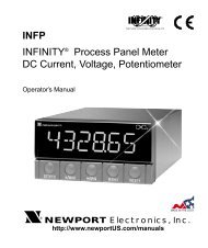
12<strong>HX94A</strong> SERIES<strong>RH</strong>/<strong>Temperature</strong> <strong>Transmitter</strong>12. Calibration Procedure for <strong>HX94A</strong>C<strong>Temperature</strong> AdjustmentRecommended equipment:• Thermistor <strong>Temperature</strong> Meter, OMEGA ® Model No.: HH41• Thermistor Probe, OMEGA ® Model No.: ON-403-PP• Handheld Digital Multi-meter, OMEGA ® Model No.: HHM29B• Unregulated DC Power Supply, OMEGA ® Model No.: PSU-93 orRegulated DC Power Supply, OMEGA ® Model No.: PSR-24L1. Remove sensor head and main electronics boards from the stainlesssteel housing.2. Connect transmitter as shown in figure below.3. Apply power to transmitter and allow unit to warm up for 10 min.4. Place a precession temperature meter/probe like the recommendedHH41 meter and ON-403-PP probe next to the sensor head of your<strong>HX94A</strong>. Record the ambient temperature measured by the precessionmeter/probe.5. Based on the ambient temperature that you measured in step 4,calculate what the correct “Output Setting” should be for your<strong>HX94A</strong>.Use one of these two formulas:Ambient <strong>Temperature</strong> (°C) x (16/100) + 4 = Output SettingExample: (22°C) x (0.16) + 4 = 7.52 mAAmbient <strong>Temperature</strong> (°F - 32) x (16/180) + 4 = Output SettingExample: (72°F - 32) x (0.0888) + 4 = 7.55 mA6. Adjust potentiometer “P4” for the correct output reading from your<strong>HX94A</strong> you calculated in step 5.7. Calibration complete.23.4°C<strong>HX94A</strong>C MAIN BOARDP5HH40 METERP4FACTORYSETTINGONLYBLACK WIRERED WIREGREEN WIREWHITE WIRE++ 24V –POWER SUPPLY12.00 mA –8Figure 7 - <strong>HX94A</strong>C Calibration Procedure<strong>Temperature</strong> AdjustmentCURRENT METER
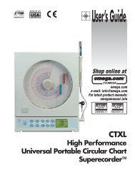
<strong>HX94A</strong> SERIES<strong>RH</strong>/<strong>Temperature</strong> <strong>Transmitter</strong>1313. Calibration Procedure for <strong>HX94A</strong>VRelative Humidity AdjustmentRecommended equipment:• Humidity Calibration Kit, OMEGA ® Model No.: HX92-CAL• Handheld Digital Multi-meter, OMEGA ® Model No.: HHM29B• Unregulated DC Power Supply, OMEGA ® Model No.: PSU-93 orRegulated DC Power Supply, OMEGA ® Model No.: PSR-24L1. Remove sensor head and main electronics boards from the stainlesssteel housing.2. Connect transmitter as shown in figure below.3. Apply power to transmitter and allow to warm up for 10 min.4. Place the sensor head into the 11% <strong>RH</strong> calibration bottle as below andallow the readings to stabilize for 10 min.5. Adjust potentiometer “P3” for an output reading of 0.110 Vdc.6. Place the sensor head into the 75% <strong>RH</strong> calibration bottle and allowthe readings to stabilize for 10 min.7. Adjust potentiometer “P2” for a output reading of 0.750 Vdc.8. Repeat steps 4, 5, 6, 7 as necessary until proper readings aremaintained.9. Reinstall the sensor head and main electronics back into the stainlesssteel housing.10. Calibration complete.<strong>HX94A</strong>V MAIN BOARDP3P2WHITE WIRERED WIREBLACK WIREGREEN WIRE+ –24VPOWER SUPPLYHX92CAL-KIT+ 0.50 Vdc –VOLTAGE METERFigure 8 - <strong>HX94A</strong>V Calibration ProcedureRelative Humidity Adjustment9
14<strong>HX94A</strong> SERIES<strong>RH</strong>/<strong>Temperature</strong> <strong>Transmitter</strong>14. Calibration Procedure for <strong>HX94A</strong>V<strong>Temperature</strong> AdjustmentRecommended equipment:• Thermistor <strong>Temperature</strong> Meter, OMEGA ® Model No.: HH41• Thermistor Probe, OMEGA ® Model No.: ON-403-PP• Handheld Digital Multi-meter, OMEGA ® Model No.: HHM29B• Unregulated DC Power Supply, OMEGA ® Model No.: PSU-93 orRegulated DC Power Supply, OMEGA ® Model No.: PSR-24L1. Remove sensor head and main electronics boards from the stainlesssteel housing.2. Connect transmitter as shown in figure below.3. Apply power to transmitter and allow unit to warm up for 10 min.4. Place a precession temperature meter/probe like the recommendedHH41 meter and ON-403-PP probe next to the sensor head of your<strong>HX94A</strong>. Record the ambient temperature measured by themeter/probe.5. Based on the ambient temperature that you measured in step 4.,calculate what the correct “Output Setting” should be for your<strong>HX94A</strong>.Use one of these two formulas:Ambient <strong>Temperature</strong> (°C) x (1/100) = Output SettingExample: 22°C x 0.010 = 0.220 VdcAmbient <strong>Temperature</strong> (°F - 32) x (1/180) = Output SettingExample: (72°F - 32) x (0.0888) + 4 = 7.55 mA6. Adjust potentiometer “P4” for the correct output reading from your<strong>HX94A</strong> you calculated in step 5.7. Calibration complete.23.4°C<strong>HX94A</strong>V MAIN BOARDP5P4FACTORYSETTINGONLYWHITE WIREGREEN WIREBLACK WIRE+24V–HH40 METERPOWER SUPPLYRED WIRE+0.50 Vac–VOLTAGE METER10Figure 9 - <strong>HX94A</strong>V Calibration Procedure<strong>Temperature</strong> Adjustment
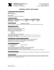
<strong>HX94A</strong> SERIES<strong>RH</strong>/<strong>Temperature</strong> <strong>Transmitter</strong>1515. MaintenanceIf your Humidity transmitter will be used in a dusty environment, theprotective sensor filter, if clogged, may be removed for cleaning.Unscrew the protective cover and gently blow compressed air throughthe filter screen. A soft brush may also be used to remove dirt particlesfrom the screen.If the sensor is subjected to 100% condensation, it must be dried toobtain correct readings. There will be no permanent damage orcalibration shift to the unit.Units should not be exposed to high concentrations of ammonia oralcohol vapors.FILTER SCREENFigure 10 - Sensor Filter Cap Removal11
16<strong>HX94A</strong> SERIES<strong>RH</strong>/<strong>Temperature</strong> <strong>Transmitter</strong>16. SpecificationsRelative HumidityMeasuring Range:Accuracy:Repeatability:Operating<strong>Temperature</strong> Range:Output:Model: <strong>HX94A</strong>CModel : <strong>HX94A</strong>VPower:Max Loop Resistance:Max Output Load:<strong>RH</strong> Time Constant (90%response at 25ºC, inmoving air at 1m/s):Sensor Type:<strong>Temperature</strong>Measuring Range:Accuracy:Repeatability:Output:Model: <strong>HX94A</strong>C4 toModel : <strong>HX94A</strong>VPower:Max Loop Resistance:Sensor Type:3 - 95% (non-condensing)±2.5% @ 22°C (72ºF) from 20 to 80% <strong>RH</strong>;±3.1% @ 22°C (72ºF) below 20 and above80% <strong>RH</strong>; with an added temperaturecoefficient error of ±0.1% <strong>RH</strong>/°F (bothincreasing and decreasing in temperature).± 1 % <strong>RH</strong>0 to 100ºC (32 to 212ºF)4 to 20 mA (Scaled for 0 to 100% <strong>RH</strong>)0 to 1 Vdc (Scaled for 0 to 100% <strong>RH</strong>)6 –30 Vdc @ 20mAOhms = (V supply – 6 V)/0.02 A200 Ohms (Voltage models)>10 seconds, 10 to 90% <strong>RH</strong>>15 seconds, 90 to 10% <strong>RH</strong>Thin Film Polymer Capacitor0 to 100ºC (32 to 212ºF)±0.6ºC (1ºF)± 0.3ºC (0.5ºF)20 mA, Scaled 0 to 100ºC (32 to 212ºF)0 to 1 Vdc, Scaled 0 to 100ºC (32 to 212ºF)12 - 30 Vdc @ 30mAOhms = (V supply – 6 V)/0.02 A100 Ohm Platinum RTD12
<strong>HX94A</strong> SERIES<strong>RH</strong>/<strong>Temperature</strong> <strong>Transmitter</strong>1717. General SpecificationsEnclosure Housing:Electrical Connections<strong>HX94A</strong>C, <strong>HX94A</strong>V:<strong>HX94A</strong>CW, <strong>HX94A</strong>VW,<strong>HX94A</strong>CNPT<strong>HX94A</strong>VNPT:Dimensions:Weight(with mounting kit)316 Stainless Steel, Nema-41 m (3') 4-conductor shielded PVC cablewith connector termination. 4 pin matingconnector included that accepts 26 to 18AWG wire.1 m (3') 4 conductor , shielded PVCcable with stripped lead termination.See “Mounting” Section200 g. (7 oz)13
<strong>HX94A</strong> SERIES<strong>RH</strong>/<strong>Temperature</strong> <strong>Transmitter</strong>NOTES:14
WARRANTY/DISCLAIMEROMEGA ENGINEERING, INC. warrants this unit to be free of defects in materials andworkmanship for a period of 13 months from date of purchase. OMEGA’s WARRANTY addsan additional one (1) month grace period to the normal one (1) year product warranty tocover handling and shipping time. This ensures that OMEGA’s customers receive maximumcoverage on each product.If the unit malfunctions, it must be returned to the factory for evaluation. OMEGA’s CustomerService Department will issue an Authorized Return (AR) number immediately upon phone orwritten request. Upon examination by OMEGA, if the unit is found to be defective, it will berepaired or replaced at no charge. OMEGA’s WARRANTY does not apply to defects resultingfrom any action of the purchaser, including but not limited to mishandling, improperinterfacing, operation outside of design limits, improper repair, or unauthorized modification.This WARRANTY is VOID if the unit shows evidence of having been tampered with or showsevidence of having been damaged as a result of excessive corrosion; or current, heat, moistureor vibration; improper specification; misapplication; misuse or other operating conditionsoutside of OMEGA’s control. Components in which wear is not warranted, include but are notlimited to contact points, fuses, and triacs.OMEGA is pleased to offer suggestions on the use of its various products. However,OMEGA neither assumes responsibility for any omissions or errors nor assumesliability for any damages that result from the use of its products in accordance withinformation provided by OMEGA, either verbal or written. OMEGA warrants onlythat the parts manufactured by the company will be as specified and free ofdefects. OMEGA MAKES NO OTHER WARRANTIES OR REPRESENTATIONS OF ANYKIND WHATSOEVER, EXPRESSED OR IMPLIED, EXCEPT THAT OF TITLE, AND ALLIMPLIED WARRANTIES INCLUDING ANY WARRANTY OF MERCHANTABILITY ANDFITNESS FOR A PARTICULAR PURPOSE ARE HEREBY DISCLAIMED. LIMITATION OFLIABILITY: The remedies of purchaser set forth herein are exclusive, and the totalliability of OMEGA with respect to this order, whether based on contract, warranty,negligence, indemnification, strict liability or otherwise, shall not exceed thepurchase price of the component upon which liability is based. In no event shallOMEGA be liable for consequential, incidental or special damages.CONDITIONS: Equipment sold by OMEGA is not intended to be used, nor shall it be used: (1)as a “Basic Component” under 10 CFR 21 (NRC), used in or with any nuclear installation oractivity; or (2) in medical applications or used on humans. Should any Product(s) be used in orwith any nuclear installation or activity, medical application, used on humans, or misused inany way, OMEGA assumes no responsibility as set forth in our basic WARRANTY/ DISCLAIMERlanguage, and, additionally, purchaser will indemnify OMEGA and hold OMEGA harmless fromany liability or damage whatsoever arising out of the use of the Product(s) in such a manner.RETURN REQUESTS/INQUIRIESDirect all warranty and repair requests/inquiries to the OMEGA Customer Service Department.BEFORE RETURNING ANY PRODUCT(S) TO OMEGA, PURCHASER MUST OBTAIN ANAUTHORIZED RETURN (AR) NUMBER FROM OMEGA’S CUSTOMER SERVICE DEPARTMENT(IN ORDER TO AVOID PROCESSING DELAYS). The assigned AR number should then bemarked on the outside of the return package and on any correspondence.The purchaser is responsible for shipping charges, freight, insurance and proper packaging toprevent breakage in transit.FOR WARRANTY RETURNS, please havethe following information available BEFOREcontacting OMEGA:1. Purchase Order number under whichthe product was PURCHASED,2. Model and serial number of the productunder warranty, and3. Repair instructions and/or specificproblems relative to the product.FOR NON-WARRANTY REPAIRS, consultOMEGA for current repair charges. Have thefollowing information available BEFOREcontacting OMEGA:1. Purchase Order number to cover theCOST of the repair,2. Model and serial number of theproduct, and3. Repair instructions and/or specific problemsrelative to the product.OMEGA’s policy is to make running changes, not model changes, whenever an improvement is possible.This affords our customers the latest in technology and engineering.OMEGA is a registered trademark of OMEGA ENGINEERING, INC.© Copyright 2009 OMEGA ENGINEERING, INC. All rights reserved. This document may not be copied, photocopied,reproduced, translated, or reduced to any electronic medium or machine-readable form, in whole or in part, withoutthe prior written consent of OMEGA ENGINEERING, INC.
Where Do I Find Everything I Need forProcess Measurement and Control?OMEGA…Of Course!Shop online at omega.com SMTEMPERATURE Thermocouple, RTD & Thermistor Probes, Connectors, Panels & Assemblies Wire: Thermocouple, RTD & Thermistor Calibrators & Ice Point References Recorders, Controllers & Process Monitors Infrared PyrometersPRESSURE, STRAIN AND FORCE Transducers & Strain Gages Load Cells & Pressure Gages Displacement Transducers Instrumentation & AccessoriesFLOW/LEVEL Rotameters, Gas Mass Flowmeters & Flow Computers Air Velocity Indicators Turbine/Paddlewheel Systems Totalizers & Batch ControllerspH/CONDUCTIVITY pH Electrodes, Testers & Accessories Benchtop/Laboratory Meters Controllers, Calibrators, Simulators & Pumps Industrial pH & Conductivity EquipmentDATA ACQUISITION Data Acquisition & Engineering Software Communications-Based Acquisition Systems Plug-in Cards for Apple, IBM & Compatibles Datalogging Systems Recorders, Printers & PlottersHEATERS Heating Cable Cartridge & Strip Heaters Immersion & Band Heaters Flexible Heaters Laboratory HeatersENVIRONMENTALMONITORING AND CONTROL Metering & Control Instrumentation Refractometers Pumps & Tubing Air, Soil & Water Monitors Industrial Water & Wastewater Treatment pH, Conductivity & Dissolved Oxygen InstrumentsM2750A/0509