Manual - NEWPORT
Manual - NEWPORT
Manual - NEWPORT

Create successful ePaper yourself
Turn your PDF publications into a flip-book with our unique Google optimized e-Paper software.
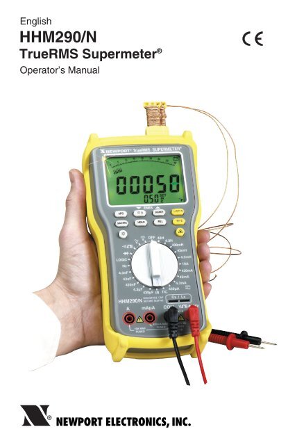
EnglishHHM290/NTrueRMS Supermeter ®Operator’s <strong>Manual</strong>®<strong>NEWPORT</strong> ELECTRONICS, INC.
SAFETY INFORMATIONSAFETY INFORMATION• Do Not use the meter if the meter or the test leads look damaged, or if you suspect thatthe meter is not operating properly.• This meter is not recommended for high voltage industrial use. For example, it is notrecommended for 440 VAC or 600 VAC industrial power mains measurement. The unitis intended for use as follows:- Low energy circuits up to 1000 VDC or 750 VAC.- High energy circuits up to 250 VAC or VDC.Accidental misuse by connection across a high voltage, high energy power sourcewhen the meter is set up for current (mA) measurement may be very hazardous.• Do Not Operate the meter with the two test leads and the thermocouple probeconnected at the same time. Unplug the test leads from the meter before makingthermocouple temperature measurement. Unplug the thermocouple probe from themeter before making other types of measurements.• Use caution when working above 60 VDC or 30 VAC. Such voltages pose a shockhazard.• Turn off power to the circuit under test before cutting, unsoldering, or breaking thecircuit. Small amounts of current can be dangerous.• When using the test leads, keep your fingers behind the finger guards.• Measuring voltages which exceeds the limits of this multimeter may damage the meterand expose the operator to a shock hazard. Always recognize the voltage limits asstated in this manual and on the meter.• If the equipment is used in a manner not specified in this manual, the protection providedby the equipment may be impaired.• Do Not Operate the meter in flammable or explosive environments.• Protect the meter from moisture.• Operate the meter with the two test leads provided.• Do Not Operate the meter when the Battery Door is open.Model No.HHM290-SCHHM-TLOS520-Adapter-110VOS520-Adapter-220VACCESSORIESDescriptionSoft Carrying CaseRepalcement Test Leads110 VAC Adapter, 9 VDC @ 200mA220 VAC Adapter, 9 VDC @ 200mA1
SAFETY INFORMATIONCAUTION• USE OF CONTROLS OR ADJUSTMENTS OR PERFORMANCE OFPROCEDURES OTHER THAN THOSE SPECIFIED HERE MAY RESULT INHAZARDOUS LASER RADIATION EXPOSURE.• DO NOT LOOK AT THE LASER BEAM COMING OUT OF THE LENS OR VIEWDIRECTLY WITH OPTICAL INSTRUMENTS. EYE DAMAGE CAN RESULT.• USE EXTREME CAUTION WHEN OPERATING THE LASER SIGHTING.• NEVER POINT THE LASER BEAM AT A PERSON.• KEEP OUT OF REACH OF ALL CHILDREN.• DO NOT ATTEMPT TO OPEN THE MULTI-METER OR LASER SIGHTING THEREARE NO USER-SERVICEABLE PARTS.• DO NOT OPEN BATTERIES, DISPOSE OF IN FIRE, HEAT ABOVE 100°C (212°F),EXPOSE CONTENTS TO WATER, RECHARGE, PUT IN BACKWARDS, MIX WITHUSED OR OTHER BATTERY TYPES. IT MAY EXPLODE OR LEAK AND CAUSEPERSONAL INJURY.• DO NOT USE THE METER NEAR ANY DEVICE THAT GENERATES STRONGELECTROMAGNETIC RADIATION, IT MAY CAUSE TEMPORARY ERROR INREADING.2
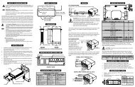
SAFETY INFORMATIONLaser ApertureLaser SwitchLaser Warning& CertificationLabelInfrared MeasurementDual ThermocoupleInput (K type T/C)Non-isolatedAnalog BarGraphCustom MadeBacklit LCDFunction SwitchTerminal JacksTerminal Socketfor Inductance &CapacitanceMeasurementDC Adapter InputBack View Of SupermeterBattery Door OpenBatteriesAA Size (6)Fuse, 10A / 600VFuse, 0.5A / 250V3
SAFETY INFORMATIONSafety Warnings and IEC SymbolsThis device is marked with international safety and hazard symbols in accordance with IEC1010. It is important to read and follow all precautions and instructions in this manual beforeoperating or commissioning this device as it contains important information relating tosafety and EMC. Failure to follow all safety precautions may result in injury and or damageto your equipment. Use of this device in a manner not specified by the manufacturer mayimpair protection provided within the unit.IEC symbolsDescriptionCaution-Risk of Electric shockCaution-Refer to Accompanying documentsDirect CurrentAlternating CurrentEarth (Ground) TerminalEquipment protected throughout by Double InsulationLaser Symbol4
OPERATIONOPERATIONBefore taking any measurements, read the Safety Information Section. Always examinethe instrument for damage, contamination (excessive dirt, grease, etc.) and defects.Examine the test leads for cracked or frayed insulation. If any abnormal conditions exist donot attempt to make any measurements. For normal operation when changing rangesthrough OFF range, please wait for one second.FUNCTIONS OF BUTTONSButtonWhen the unit is turned on, the Auto Power-On (APO) mode is disabled meaning that themeter shuts itself off after about 30 minutes of continuous operation. This feature savesbattery life if the meter is un-attended.Pressing the button, enables the APO mode, and an APO icon appears on the displaymeaning that the meter will not shut itself off unless it is turned off by the user. This featureis also desirable when the meter is used to monitor a parameter for an extended period oftime. Using the DC adapter, it will take over the battery power to save battery life. Pressingthe button again will disable the APO mode.Button (Double Duty)Pressing this button will toggle between AC and DC current measurement. In infraredtemperature measurement "IR" mode, pressing this button decreases the Emissivity valueof the target.Button (Double Duty)Press button to select the <strong>Manual</strong> Range mode and turn off the "AUTO" annunciator.In the <strong>Manual</strong> Range mode. Each time you press button, the range (and the input rangeannunciator) increments, and a new value is displayed. To exit the <strong>Manual</strong> Range modeand return to autoranging, press and hold down button for 2 seconds. The "AUTO"annunciator turns back on.In infrared temperature measurement "IR" mode, pressing this button increases theEmissivity value of the target.ButtonIn thermocouple temperature "T/C" mode, pressing this button scrolls thru T1, T2, and (T1-T2) temperature readings. In AC current and AC voltage ranges, press and hold this buttonfor 2 seconds, Frequency changes between 50 Hz and 60 Hz.5
OPERATIONButtonPress to enter the MAX MIN AVG Recording mode (manual range only). The "REC","APO" annunciator turns on and tenable the APO mode. Meter do not take records whenthe display reads overrange (+/- OL).Push to cycle through the maximum(MAX), minimum(MIN), average(AVG) andpresent readings. Press and hold down the for 2 seconds to exit and erase recordedreading.ButtonPressing the key to enter the Data Hold mode, the "HOLD" annunciator is displayed.When HOLD mode is selected, the meter held the present readings and stops all furthermeasurements.Pressing themeasurements.key again to cancel HOLD mode causing meter to resume takingButtonPress to enter the Relative mode, zero the display, and store the displayed reading asa reference value. The relative mode annunciator "REL" is displayed.Press again to exit the relative mode.ButtonPressing this button toggles the temperature display between Degrees Celsius(°C) orDegrees Fahrenheit(°F).ButtonPress button to toggle on and off of display backlight. The backlight will switch-offautomatically after 30 seconds.ButtonPress & hold to turn on the laser beam. Release the button to turn off the laser beam. Whenthe laser beam is on, a laser icon appears on the display.There is a switch in front of the laser aperture which selects between laser Dot or laserCircle.6
OPERATIONNOTEUnplug any thermocouple probes from the thermocouple input sockets beforemaking any other types of measurements.Voltage Measurements1. Connect the red test lead to the "V " jack and the blacktest lead to the "COM" jack of the multimeter.2. For DC measurement, set the Function switch " V "position. For AC measurement, set the Function switch" V " position.3. Connect the other end of the test leads to the device orcircuit being measured.Current Measurements1. Set the Function switch anywhere from 430µA to 10Adepending on the range.2. In the 10A position, connect test leads to "A" and "COM"jacks. In lower ranges, connect test leads to "mAµA" &"COM" jacks.3. For AC measurement, press the button, and an ACicon will appear on the display.4. Connect the multimeter in Series with the circuit beingmeasured.Resistance & Continuity Measurements1. Set the Function switch to the resistance position.2. Remove power from the device or circuit under test.3. Connect the test lead to the "V " & "COM" jacks.4. The beeper sounds once, if the resistance beingmeasured is less than 30 Ohms.7
OPERATIONNOTEUnplug the test leads from the multimeter before making any type of thermocoupletemperature measurements. The two thermocouple inputs are not isolated fromeach other. If using grounded probes, do not use on any conductive surface.Thermocouple Temperature Measurements1. Set the Function switch to "T/C" position.2. The multimeter can accept up to two K type thermocoupleinputs.3. Plug in the thermocouple probe(s) to the mating built-inconnector(s) in the meter.4. The temperature is displayed in either Degree Celsius(°C) or Degree Fahrenheit (°F). To change thetemperature Engineering unit, press the button.5. Press the button to display T1, T2, or T1-T2.Infrared (Non-Contact) Temperature Measurements1. Set the Function switch to "IR" position.2. Press the or buttons to set the Emissivity of thetarget.3. Aim at the target. Press & hold the button to turn onthe laser beam. There is a switch in front of the laserbeam aperture which projects either Laser Dot or LaserCircle. The laser dot indicates the center of the opticalfield of view. The laser circle indicates the perimeter ofthe field of view. There is a 0.63 inches offset betweenthe laser aperture and the center of the optical field ofview. The laser beam only turns on when the buttonis pressed & held Releasing the button turns off the laserbeam.4. The target must be larger than the optical field of view ofthe multimeter (Spot Size).5. Read the temperature.Frequency Measurements1. Set the Function switch to the "Hz" position.2. Connect the test leads from the point of measurement tothe "V" & "COM" jacks of the meter.3. Read the frequency.8
OPERATIONNOTEUnplug the test leads and thermocouple probes from the multimeter beforemaking any capacitance or inductance measurement.Capacitance MeasurementsDo Not apply external voltage to the Cx Lx sockets. Makesure that the capacitor is fully discharged, otherwise damageto the meter may result.1. Set the Function switch to the desired capacitance range(µF to nF).2. Insert the capacitor leads into the Cx Lx sockets.3. Read the capacitance value.Cx/LxInductance Measurements1. Set the Function switch to the desired inductance range(mH to H).2. Insert the inductor leads into the Cx Lx sockets.3. Read the inductance value.Cx/LxDiode Tests1. Connect the red test lead to the "V " jack and the black test lead to the "COM" jack.2. Set the Function/Range switch to the " " position.3. Turn off power to the circuit under test.4. Touch probes to the diode. A forward-voltage drop is about 0.6V (typical for a silicondiode).5. Reverse probes. If the diode is good, OL is displayed. If the diode is shorted, ".000" oranother number is displayed.6. If the diode is open, OL is displayed, in both directions.7. If the junction is measured in a circuit and a low reading is obtained with both leadconnections, the junction may be shunted by a resistance of less than 1KΩ. In this casethe diode must be disconnected from the circuit for accurate testing.Logic Measurements1. Set the Function/Range switch to the Logic position.2. Connect the red test lead to the "V " jack and the black test lead to the "COM" jack.3. Connect the red test lead to the test point and the black lead to the common bus of thelogic circuit.4. A " "on the display indicates TTL logic high and a " " indicates a TTL logic low. Bothindicators are on when the point of measurement is toggling high and low.9
SPECIFICATIONSSPECIFICATIONSDisplay:Backlit liquid crystal display (LCD) with a maximumdigital reading of 43000 counts. Includes an AnalogBar Graph of 40 counts.Display Resolution:Range: → Resolution (1 Digit)0-4.3 → .00010-43 → .0010-430 → .010-4300 → .10-43000 → 1Polarity:Automatic, positive implied, negative polarity indication.Overrange:"OL" or "-OL" is displayed.Low battery indication: The " " is displayed when the battery voltage dropsbelow the operating level.Measurement rate:2/sec, nominal; 1/sec, temperature.20/sec, Analog display.Operating Environment:0°C to 40°C at
SPECIFICATIONSDC VOLTSRanges:430mV(manual), 4.3V, 43V, 430V, 1000VResolution: 10µVAccuracy:±(0.25% rdg + 10 Digits)Example: On 43V Range ±0.25% Rdg + 0.01VInput impedance:>10MΩOverload protection:1000VDC or 750VAC rmsLow Energy circuits:Up to 1000VDCHigh Energy circuits:Up to 250VDCAC VOLTS (50Hz-2KHz)Ranges:400mV(manual), 4.0V, 40V, 400V, 750VResolution: 10µVAccuracy:±(% of Rdg + No. of digits)Range 50Hz-100H 100Hz-500Hz 500Hz-2KHz400mV4.0V40V400V750V±(2.0% rdg + 30 digits)±(0.75% rdg + 20 digits)N/AN/A±(1.5% rdg + 30 digits)Input impedance:Overload protection:Low Energy circuits:High Energy circuits:DC CURRENTRanges:Resolution:Accuracy:Burden voltage:Input protection:>10MΩ1000VDC or 750VAC rmsUp to 750VACUp to 250VAC430µA, 4.3mA, 43mA, 430mA, 10A10nA±(0.5% rdg + 10 digits)on 430µA to 430mA ranges±(2.0% rdg + 10 digits) on 10A range1.4V on all ranges, execpt1.5V on 10A range0.5A / 250V fast blow fuse10A / 600V fast blow ceramic fuse11
SPECIFICATIONSAC CURRENT (50Hz-1KHz)Ranges:Resolution:Accuracy:Burden voltage:Input protection:RESISTANCERanges:Resolution:Accuracy:Audible indication:Open circuit volts:Overload protection:400µA, 4.0mA, 40mA, 400mA, 10A10nA±(1.0% rdg + 20 digits) on400µA to 400mA ranges±(2.5% rdg + 20 digits)on 10A range1.4V on all ranges, execpt1.5V on 10A range0.5A / 250V fast blow fuse10A / 600V fast blow ceramic fuse410Ω 4.1KΩ, 41KΩ, 410KΩ, 4100KΩ, 41MΩ10mΩ±(0.3% rdg + 20 digits) on410Ω to 4100KΩ ranges±(1.5% rdg + 30 digits) on41MΩ ranges
SPECIFICATIONSFREQUENCYRanges:Resolution:Accuracy:Sensitivity:Overload protection:100Hz,1000Hz,10KHz,100KHz,500KHz,1MHz0.01Hz (under 100Hz)±(0.1% rdg + 3dgts)1Vrms min500VDC or AC rmsCAPACITANCERanges: 4.3nF, 43nF, 430nF, 4.3µF, 430µFResolution:0.1pFAccuracy:±(5.0% rdg + 100 digits)Test frequency:4.3nF, 43nF ranges 1KHz430nF, 4.3µF ranges 270Hz430µF range 27HzINDUCTANCERanges:4.3mH,43mH,430mH,4.3H,43HResolution: 1µHAccuracy:±(5.0% rdg + 200 digits) on 4.3mH range±(5.0% rdg + 100 digits) on 43mH to 43H rangesTest frequency:4.3mH,43mH ranges 1KHz430mH,4.3H ranges 270Hz43H range 27HzTest conditions:quality factor > 5 in 270HzLASER SIGHTINGLaser sighting:Wavelength(Color):Operating distance:Maximum Power Output:12 point Laser circle630-670nm(RED)2 to 25 feet
SPECIFICATIONSINFRARED ELECTRICALTemperature Range: -20°C to 550°C / -4°F to 1022°FDisplay Resolution: 1°C / 1°FAccuracy: 2% of reading or 3°F, whichever is greater, at 72°Fambient and Emissivity of 0.95 or greaterTemperature Coefficient: ±0.2% of reading or ±0.36°F/0.2°C, per °F/°C changein ambient temperature whichever is greater, above82.4°F/28°C or below 64.4°F/18°C ambienttemperaturesResponse Time:1.5 secondsSpectral Response:6 to 14µm nominalEmissivity: 0.10 to 1.00 by step of 0.01Detection Element:ThermopileOptical Lens:Fresnel LensField of View: 100mmØ at 1000mm (2.5"Ø at 25")Spot size increases with distance from the probe tip as shown(Spot Diameter measured at 90 % Energy)14
SPECIFICATIONSK-type thermocouple ELECTRICALTemperature Scale:Celsius or Fahrenheit user-selectableMeasurement Range: Thermocouple RangeK-TYPE -200°C to 1372°C, -328°F to1999°FAuto range:0.1°C/1°C, 0.1°F/1°FAccuracy:Accuracy is specified for operating temperatures overthe range of 18°C to 28°C (64°F to 82°F) for 1 year,not including thermocouple error.±(0.1%rdg + 1°C) on -60°C to 1372°C±(0.1%rdg + 2°C) on -60°C to -200°C±(0.1%rdg + 2°F) on -76°F to 2501°F±(0.1%rdg + 4°F) on -76°F to -328°FTemperature Coefficient: ±0.2% of reading or ±0.36°F/0.2°C, whichever isgreater, change in accuracy per °F/°C change inambient operating temperature above 82.4°F/28°C orbelow 64.4°F/18°C.Input Protection:24V dc or 24V ac rms maximum input voltage on anycombination of input pins.Input Connector:Accepts standard miniature thermocouple connectors(flat blades spaced 7.9mm, center to center), SMPInput (T1,T2) isolationNoneHow to specify the target emissivityIn order to determine an unknown target Emissivity:A. <strong>Manual</strong>:1. Set the Function switch to T/C.2. Plug in a K type surface thermocouple probe to the meter.3. Measure the target temperature using the surface probe.4. Unplug the surface probe from the meter.5. Set the Function switch to IR.6. Aim at the target. Press & hold the button to turn on the laser beam for positioning.7. Adjust the Emissivity button until the meter reads the same temperature measuredvia the thermocouple probe. Read the new Emissivity setting.B. Auto:1. Set the Function switch to T/C.2. Plug in a K type surface thermocouple probe to the meter.3. Measure the target temperature using the surface probe.4. Press and hold the button for 2 seconds to save the reading.5. Unplug the surface probe from the meter.6. Set the function switch to IR.7. Aim at the target. Press & hold the button to turn on the laser beam for positioning.8. Press and hold the button for 2 seconds, to set the Emissivity automatically.15
SPECIFICATIONS2.About InfraredInfrared radiation is a form of energy (electromagnetic radiation), and has the property thatit passes easily through air while it is easily absorbed by solid matter. With an emissionthermometer which operates by detecting infrared radiation accurate measurement ispossible, irrespective of the air temperature or the measurement distance.3.Emission Thermometer StructureInfrared radiation which has been emitted from the object is focused upon an infraredradiation sensor, via an optical system. This includes a lens which is transparent toinfrared radiation, and 5.3µm cut off filter. The output signal from the infrared radiationsensor is input to an electronic circuit along with the output signal from a standardtemperature sensor (Thermopile).4.EmissivityAll objects emit invisible infrared energy. The amount of energy emitted is proportionalto the object's temperature and its ability to emit IR energy. This ability, called emissivity,is based upon the material that the object is made of and its surface finish. Emissivityvalues range from 0.10 for a very reflective object to 1.00 for a black body. Factory setemissivity value of 0.95, which cover 90% of typical applications.5.If the surface to be measured is covered by frost or other material, clean it to expose thesurface.6.If the surface to be measured is highly reflective, apply masking tape or matt finish blackpaint to the surface.7.If the meter seems to be giving incorrect readings check the front lens. There may becondensation or debris obstructing the lens; clean per instructions in the maintenancesection.Substance Thermal Substance ThermalemissivityemissivityAsphalt 0.90 to 0.98 Cloth (black) 0.98Concrete 0.94 Human skin 0.98Cement 0.96 Lather 0.75 to 0.80Sand 0.90 Charcoal (powder) 0.96Earth 0.92 to 0.96 Lacquer 0.80 to 0.95Water 0.92 to 0.96 Lacquer (matt) 0.97Ice 0.96 to 0.98 Rubber (black) 0.94Snow 0.83 Plastic 0.85 to 0.95Glass 0.90 to 0.95 Timber 0.90Ceramic 0.90 to 0.94 Paper 0.70 to 0.94Marble 0.94 chromium oxides 0.81Plaster 0.80 to 0.90 Copper oxides 0.78Mortar 0.89 to 0.91 lron oxides 0.78 to 0.82Brick (red) 0.93 to 0.96 Textiles 0.9016
MAINTENANCEMAINTENANCEWARNINGRemove test leads before changing battery or fuseor performing any servicing.Battery ReplacementPower is supplied by 6 pcs 1.5V (AA size) battery (UM-3 R6). The " " appears on the LCDdisplay when replacement is needed. To replace the battery, remove the two screws fromthe back of the meter and lift off the battery case. Remove the battery from battery contacts.Fuse ReplacementIf no current measurements are possible, check for a blown overload protection fuse. Thereare two fuses; F1 for the "mA" jack and F2 for the "10A" jack. For access to fuses, removethe two screws from the back of the meter and lift off the battery case. Replace F1 only withthe original type 10A/600V, fast acting fuse. Replace F2 only with the original type 0.5A/250V, fast acting ceramic fuse.CleaningPeriodically wipe the case with a damp cloth and detergent, do not use abrasives orsolvents. Clean the front lens by blowing off loose particles or using a damp, soft, cleancloth.17
Warranty/Disclaimer<strong>NEWPORT</strong> ELECTRONICS, INC. warrants this unit to be free of defects in materials and workmanshipfor a period of one (1) year from date of purchase. In addition to <strong>NEWPORT</strong>’s standard warrantyperiod, <strong>NEWPORT</strong> ELECTRONICS will extend the warranty period for one (1) additional year if thewarranty card enclosed with each instrument is returned to <strong>NEWPORT</strong>.If the unit malfunctions, it must be returned to the factory for evaluation. <strong>NEWPORT</strong>’s CustomerService Department will issue an Authorized Return (AR) number immediately upon phone or writtenrequest. Upon examination by <strong>NEWPORT</strong>, if the unit is found to be defective, it will be repaired orreplaced at no charge. <strong>NEWPORT</strong>’s WARRANTY does not apply to defects resulting from any actionof the purchaser, including but not limited to mishandling, improper interfacing, operation outside ofdesign limits, improper repair, or unauthorized modification. This WARRANTY is VOID if the unitshows evidence of having been tampered with or shows evidence of having been damaged as aresult of excessive corrosion; or current, heat, moisture or vibration; improper specification;misapplication; misuse or other operating conditions outside of <strong>NEWPORT</strong>’s control. Componentswhich wear are not warranted, including but not limited to contact points, fuses, and triacs.<strong>NEWPORT</strong> is pleased to offer suggestions on the use of its various products. However, <strong>NEWPORT</strong>neither assumes responsibility for any omissions or errors nor assumes liability for any damages thatresult from the use of its products in accordance with information provided by <strong>NEWPORT</strong>, eitherverbal or written. <strong>NEWPORT</strong> warrants only that the parts manufactured by it will be as specified andfree of defects. <strong>NEWPORT</strong> MAKES NO OTHER WARRANTIES OR REPRESENTATIONS OF ANY KINDWHATSOEVER, EXPRESS OR IMPLIED, EXCEPT THAT OF TITLE, AND ALL IMPLIED WARRANTIESINCLUDING ANY WARRANTY OF MERCHANTABILITY AND FITNESS FOR A PARTICULAR PURPOSEARE HEREBY DISCLAIMED. LIMITATION OF LIABILITY: The remedies of purchaser set forth herein areexclusive, and the total liability of <strong>NEWPORT</strong> with respect to this order, whether based on contract,warranty, negligence, indemnification, strict liability or otherwise, shall not exceed the purchaseprice of the component upon which liability is based. In no event shall <strong>NEWPORT</strong> be liable forconsequential, incidental or special damages.CONDITIONS: Equipment sold by <strong>NEWPORT</strong> is not intended to be used, nor shall it be used: (1) as a“Basic Component” under 10 CFR 21 (NRC), used in or with any nuclear installation or activity; or (2)in medical applications or used on humans. Should any Product(s) be used in or with any nuclearinstallation or activity, medical application, used on humans, or misused in any way, <strong>NEWPORT</strong>assumes no responsibility as set forth in our basic WARRANTY/DISCLAIMER language, and,additionally, purchaser will indemnify <strong>NEWPORT</strong> and hold <strong>NEWPORT</strong> harmless from any liability ordamage whatsoever arising out of the use of the Product(s) in such a manner.Return Requests/InquiriesDirect all warranty and repair requests/inquiries to the <strong>NEWPORT</strong> Customer Service Department.BEFORE RETURNING ANY PRODUCT(S) TO <strong>NEWPORT</strong>, PURCHASER MUST OBTAIN ANAUTHORIZED RETURN (AR) NUMBER FROM <strong>NEWPORT</strong>’S CUSTOMER SERVICE DEPARTMENT (INORDER TO AVOID PROCESSING DELAYS). The assigned AR number should then be marked on theoutside of the return package and on any correspondence.The purchaser is responsible for shipping charges, freight, insurance and proper packaging toprevent breakage in transit.FOR WARRANTY RETURNS, please have thefollowing information available BEFOREcontacting <strong>NEWPORT</strong>:1. Purchase Order number under which theproduct was PURCHASED,2. Model and serial number of the productunder warranty, and3. Repair instructions and/or specific problemsrelative to the product.FOR NON-WARRANTY REPAIRS, consult<strong>NEWPORT</strong> for current repair charges. Have thefollowing information available BEFOREcontacting <strong>NEWPORT</strong>:1. Purchase Order number to cover the COSTof the repair,2. Model and serial number of the product, and3. Repair instructions and/or specificproblems relative to the product.<strong>NEWPORT</strong>’s policy is to make running changes, not model changes, whenever an improvement is possible. Thisaffords our customers the latest in technology and engineering.<strong>NEWPORT</strong> is a registered trademark of <strong>NEWPORT</strong> ELECTRONICS, INC.© Copyright 2006 <strong>NEWPORT</strong> ELECTRONICS, INC. All rights reserved. This document may not be copied,photocopied, reproduced, translated, or reduced to any electronic medium or machine-readable form, in wholeor in part, without the prior written consent of <strong>NEWPORT</strong> ELECTRONICS, INC.PATENT NOTICE: U.S. PAT. 5,368,392; 5,524,984; 5,727,880; 5,465,838; 5,823,678; 5,823,679; 6,095,682;6,123,453; 6,267,500 B1; 6,341,891 B1; 6,377,400 B1; 6,540,398 B2; 6,614,830 B1; 6,633,434 B2; 6,659,639; /Canada 2,114,806; 2,116,055; 75811 D OMEGA ENGINEERING, INC./ France 2 756 920; 2 767 921; 2 772 918;2,773,213; 2 773 214 / Germany M 94 06 478.4; G 94 22 197.9; G 94 22 203.7/ Italy RM940000913/ Japan988,378/Holland 1007752; 25009-00/ Spain mod. ut. 0133292/ Slovak Republic 24565/ U.K. Registered 2041153;2,237,493; 2,320,324; GB 2331581 / EPO 0 644,408 B2; EPO 1 085 307 A1. Other U.S. and Foreign PatentsPending. Used under license.
Additional products from®Newport Electronics, Inc.CountersFrequency MetersPID ControllersClock/TimersPrintersProcess MetersOn/Off ControllersRecordersRelative HumidityTransmittersThermocouplesThermistorsWireRate MetersTimersTotalizersStrain Gauge MetersVoltmetersMultimetersSoldering Iron TesterspH penspH ControllerspH ElectrodesRTDsThermowellsFlow SensorsFor Immediate AssistanceIn the U.S.A. and Canada: 1-800-<strong>NEWPORT</strong> ®In Mexico: (001) 800-826-6342Or call your local <strong>NEWPORT</strong> Office.<strong>NEWPORT</strong>net SM On-Line Servicenewportus.comInternet e-mailinfo@newportus.comIt is the policy of <strong>NEWPORT</strong> to comply with all worldwide safety and EMC/EMI regulationsthat apply. <strong>NEWPORT</strong> is constantly pursuing certification of its products to the EuropeanNew Approach Directives. <strong>NEWPORT</strong> will add the CE mark to every appropriate deviceupon certification.The information contained in this document is believed to be correct, but <strong>NEWPORT</strong> Electronics, Inc. accepts no liabilityfor any errors it contains, and reserves the right to alter specifications without notice.WARNING: These products are not designed for use in, and should not be used for, patient-connected applications.Supermeter ® is a registered trademark of OMEGA Engineering, Inc., used uner license.